Surface roughness is a set of surface irregularities with relatively small steps.
To separate surface roughness from other irregularities with relatively large steps (shape deviations and waviness), it is considered within a limited area, the length of which is called the base length .
Surface roughness is assessed by the irregularities of the profile obtained by cutting the real surface with a plane.
The numerical values of the surface roughness parameters are determined from a single base, for which the profile middle line , i.e. baseline.
To quantify roughness, three main parameters are most often used:
- Ra is the arithmetic mean of the absolute values of profile deviations within the base length.
- Rz is the height of irregularities at ten points (the sum of the average absolute values of the heights of the five largest protrusions of the profile and the depths of the five largest depressions of the profile within the base length).
- Rmax is the greatest height of profile irregularities within the base length.
Ra is preferable since it is determined by a larger number of profile points. In connection with this parameter Ra, the roughness of reference samples used for roughness assessment in industry is normalized.
Rmax and Rz parameters are used in cases where, according to functional requirements, it is necessary to limit the total height of the profile roughness, and also when direct control of Ra using profilometers or comparison samples is not possible (surfaces with small dimensions or complex configuration, for example, a cutting tool).
Requirements for surface roughness are established based on the functional purpose of the surface to ensure the specified quality of products. If this is not necessary, then roughness requirements are not established and surface roughness is not controlled.
The concept of metal surface quality after processing
After processing on a milling machine, as after other work with the workpiece, irregularities are formed on its surface - ridges and depressions (in other words, roughness and waviness). Residual stress also appears in the upper layers of the material; at some rolling depths, a difference in hardness appears, which manifests itself as hardening or hardening. Such changes affect the properties of finished products and, consequently, the quality of their surfaces. All these characteristics determine the class of metal processing.
The quality of finished parts is determined by both their physical and geometric characteristics.
- Physical quality criteria.
The surface quality of a product is determined by the relationship between the physical and mechanical properties of its central part and its outer part.
During the processing of metal workpieces, their surface is subject to plastic changes, therefore other characteristics of the material in the finished product differ from the original ones. At the same time, the outer part of the plate is strengthened and internal stresses appear in it.
After the final stage of metal processing on a milling machine, the hardened layer extends only a few hundredths of a millimeter, while after the initial impact of a cylindrical cutter its thickness averages 0.04–0.08 mm, reaching 0.12 mm. When exposed to an end mill, the parameter is 0.06–0.1 mm, although it can be 0.2 mm. The resulting internal stresses and surface hardening lower the class of metal processing by reducing the fatigue strength of the product. Such deformations shorten the service life of the part, which leads to the need for its immediate replacement.
We recommend articles on metalworking
- Steel grades: classification and interpretation
- Aluminum grades and areas of their application
- Defects in metal products: causes and search methods
- Microgeometric quality criteria.
During rough rough processing with a gear cutter at high speeds and with an increased depth of section, irregularities remain on the edge of the product, which are noticeable to the naked eye and are easily determined by touch. Roughness and waviness formed during intermediate and finishing machining at low speeds and during shallow cutting are visually invisible and can barely be felt.
The class of geometric accuracy of metal processing depends on the presence of irregularities on the surface of the product: depressions, ridges, roughness, etc. Such defects on a small surface area are called its microgeometry.
The microgeometry of the surface when processing rolled products depends on:
- cutter geometry, its quality and degree of wear;
- vibrations arising due to insufficient rigidity of the machine or its working elements;
- established settings for the operation of the milling machine (cutting speed and depth, feed per tooth, cooling);
- mechanical properties of the processed sheet and the cutter itself.
Metalworking – Mechanical – With chip removal – Metal blade tools – Turning
Turning (boring) is a method of processing a workpiece with a metal single-edged tool.
Technological parameters:
- t = from 0.03-0.05 to 7-8 mm, sometimes t = 0.002-0.006 mm;
- S = 0.05-0.1 to 1.5-2 mm/rev; (see tables No. 1-5)
- V = from 1-2 to 150-1000 m/min; (see tables No. 6-8)
- cutting forces Pz = from 10-15 to 800-900 kgf.
Turning (boring) is carried out on machines :
- Lathes
- Revolver
- Boring
- Carousel
- Automatic and semi-automatic lathes (single- and multi-spindle) with horizontal and vertical spindles
- Multi-cutting lathes
- Automatic hydrocopying lathes
- and etc.
The achieved accuracy is from 14-13 qualifications (7-5th grade) to 9-7th qualification (3-2a grade). Under more careful processing conditions - up to 5-6th quality (1st-2nd grade).
Surface roughness from class 2-3 for roughing to class 5-6 for semi-finishing; with more careful processing, it is possible to achieve a roughness of 7-10 classes (Ra = 1.25 - 0.16 microns).
Dimensional accuracy and roughness of external cylindrical surfaces when processed on lathes
Type of processing
| Quality | Roughness parameters, microns | ||
| Rz | Ra | ||
| Turning: rough semi-finish finishing thin | 13-12 | 80…60 | — |
| 11-9 | 40…20 | — | |
| 8-7 | — | 2,5 | |
| 7-6 | — | 1,25…0,63 | |
| End cutting with a cutter: rough finishing thin | 12 | 40 | — |
| 11 | 20 | — | |
| 8-7 | — | 2,50…1,25 | |
Deviation from coaxiality of the surfaces of bodies of revolution processed on lathes
| Surface treatment method | Deviation from alignment, mm |
| In centers: from one installation from two installations | 0,008…0,004 |
| 0,015…0,008 | |
| On a mandrel: machined in place (on the same machine) when the deviation from the alignment of the mandrel, spindle and workpiece is no more than ±0.002 mm | 0,008…0,004 |
| 0,012…0,008 |
Types of turning and boring:
- Roughing t = up to 3-10 mm; S = 0.15-1.0 mm/rev; Processing accuracy: 12-14 quality (5-7 grade); Surface roughness: no higher than class 3 (Rz=80 µm); The deformed surface layer can reach a thickness of 0.5-0.9 mm. Scope of application: preliminary (rough) processing of workpieces, removal of the main part of the allowance, surface preparation for subsequent processing.
- Semi-finish t = 0.5-3 mm; S = 0.15-0.7 mm/rev; V = from 5-10 to 100-150 m/min Processing accuracy: 11-12 quality (4-3 class); Surface roughness: 4-6 class (Ra = 10-2.5 microns); Scope of application: preliminary and final surface treatment. Often precedes sanding.
- Finish t = 0.1-1.0 mm; S = 0.1-0.5 mm/rev; V = from 2-5 to 100-200 m/min and more; Processing accuracy: 11-7 quality (4-2a class); Surface roughness: 7-8 class (Ra = 1.25-0.63 microns); Scope of application: final surface treatment, as well as for preparing it for final processing by other methods (superfinishing, honing, lapping).
- Thin t = from 0.002-0.006 to 0.3 mm; S = 0.02-0.12 mm/rev; V = from 100 to 1000-6000 m/min; Processing accuracy: 9-5 quality (3-1 class); Surface roughness: 8-10 class (Ra = 0.63-0.16 µm); Scope of application: final surface treatment.
Table No. 1. Feeds during rough external turning with cutters with inserts made of carbide and high-speed steel.
| Part diameter, mm | Cutter holder size, mm | Processed material | |||||||||
| Structural carbon steel, alloyed and heat-resistant | Cast iron and copper alloys | ||||||||||
| Feed S, mm/rev, at cutting depth t, mm | |||||||||||
| Until 3 | St. 3 to 5 | St. 5 to 8 | St. 8 to 12 | St.12 | Until 3 | St. 3 to 5 | St. 5 to 8 | St. 8 to 12 | St. 12 | ||
| Up to 20 | From 16 x 25 to 25 x 25 | 0,3-0,4 | — | — | — | — | — | — | — | — | — |
| St. 20 to 40 | From 16 x 25 to 25 x 25 | 0,4-0,5 | 0,3-0,4 | — | — | — | 0,4-0,5 | — | — | — | — |
| » 40 » 60 | From 16 x 25 to 25 x 40 | 0,5-0,9 | 0,4-0,8 | 0,3-0,7 | — | — | 0,6-0,9 | 0,5-0,8 | 0,4-0,7 | — | — |
| » 60 » 100 | From 16 x 25 to 25 x 40 | 0,6-1,2 | 0,5-1,1 | 0,5-0,9 | 0,4-0,8 | — | 0,8-1,4 | 0,7-1,2 | 0,6-1,0 | 0,5-0,9 | — |
| » 100 » 400 | From 16 x 25 to 25 x 40 | 0,8-1,3 | 0,7-1,2 | 0,6-1,0 | 0,5-0,9 | — | 1,0-1,5 | 0,8-1,3 | 0,8-1,1 | 0,6-0,9 | — |
| » 400 » 500 | From 20 x 30 to 40 x 60 | 1,1-1,4 | 1,0-1,3 | 0,7-1,2 | 0,6-1,2 | 0,4-1,1 | 1,3-1,6 | 1,2-1,5 | 1,0-1,2 | 0,7-0,9 | — |
| » 500 » 600 | From 20 x 30 to 40 x 60 | 1,2-1,5 | 1,0-1,4 | 0,8-1,3 | 0,6-1,3 | 0,5-1,2 | 1,5-1,8 | 1,2-1,6 | 1,0-1,4 | 0,9-1,2 | 0,8-1,0 |
| » 600 » 1000 | From 25 x 40 to 40 x 60 | 1,2-1,8 | 1,1-1,5 | 0,9-1,4 | 0,8-1,4 | 0,7-1,3 | 1,5-2,0 | 1,3-1,8 | 1,0-1,4 | 1,0-1,3 | 0,9-1,2 |
| » 1000 » 2500 | From 30 x 45 to 40 x 60 | 1,3-2,0 | 1,3-1,8 | 1,2-1,6 | 1,1-1,5 | 1,0-1,5 | 1,6-2,4 | 1,6-2,0 | 1,4-1,8 | 1,3-1,7 | 1,2-1,7 |
Notes:
1. Lower feed values correspond to smaller cutter holder sizes and stronger processed materials, upper feed values correspond to larger cutter holder sizes and less durable processed materials.
2. When processing heat-resistant steels and alloys, do not use feeds exceeding 1 mm/rev.
3. When processing discontinuous surfaces and when working with impacts, the table feed values should be reduced by a factor of 0.75-0.85.
4. When processing hardened steels, reduce the table feed values by multiplying by a factor of 0.8 for steel with HRC 44-56 and by 0.5 for steel with HRC 57-62.
Table No. 2. Feeds during rough boring on lathes, turret lathes and rotary lathes with cutters with plates made of carbide and high-speed steel.
| Cutter or mandrel | Processed material | ||||||||||||
| Diameter of the circular cross-section of the cutter or dimensions of the rectangular cross-section of the mandrel, mm | Reach of cutter or mandrel, mm | Structural carbon steel, alloyed and heat-resistant | Cast iron and copper alloys | ||||||||||
| Feed S mm/rev, at cutting depth t, mm | |||||||||||||
| 2 | 3 | 5 | 8 | 12 | 20 | 2 | 3 | 5 | 8 | 12 | 20 | ||
| Lathes and turret lathes | |||||||||||||
| 10 | 50 | 0,08 | — | — | — | — | — | 0,12-0,16 | — | — | — | — | — |
| 12 | 60 | 0,10 | 0,08 | — | — | — | — | 0,12-0,20 | 0,12-0,18 | — | — | — | — |
| 16 | 80 | 0,1-0,2 | 0,15 | 0,1 | — | — | — | 0,2-0,3 | 0,15-0,25 | 0,1-0,18 | — | — | — |
| 20 | 100 | 0,25-0,3 | 0,15-0,25 | 0,12 | — | — | — | 0,3-0,4 | 0,25-0,35 | 0,12-0,25 | — | — | — |
| 25 | 125 | 0,25-0,5 | 0,15-0,4 | 0,12-0,2 | — | — | — | 0,4-0,6 | 0,3-0,5 | 0,25-0,35 | — | — | — |
| 30 | 150 | 0,4-0,7 | 0,2-0,5 | 0,12-0,3 | — | — | — | 0,5-0,8 | 0,4-0,6 | 0,25-0,45 | — | — | — |
| 40 | 200 | — | 0,25-0,6 | 0,15-0,4 | — | — | — | — | 0,6-0,8 | 0,3-0,8 | — | — | — |
| 40 x 40 | 150 | — | 0,6-1,0 | 0,5-0,7 | — | — | — | — | 0,7-1,2 | 0,5-0,9 | 0,4-0,5 | — | — |
| 300 | — | 0,4-0,7 | 0,3-0,6 | — | — | — | — | 0,6-0,9 | 0,4-0,7 | 0,3-0,4 | — | — | |
| 60 x 60 | 150 | — | 0,9-1,2 | 0,8-1,0 | 0,6-0,8 | — | — | — | 1,0-1,5 | 0,8-1,2 | 0,6-0,9 | — | — |
| 300 | — | 0,7-1,0 | 0,5-0,8 | 0,4-0,7 | — | — | — | 0,9-1,2 | 0,7-0,9 | 0,5-0,7 | — | — | |
| 75 x 75 | 300 | — | 0,9-1,3 | 0,8-1,1 | 0,7-0,9 | — | — | — | 1,1-1,6 | 0,9-1,3 | 0,7-1,0 | — | — |
| 500 | — | 0,7-1,0 | 0,6-0,9 | 0,5-0,7 | — | — | — | — | 0,7-1,1 | 0,6-0,8 | — | — | |
| 800 | — | — | 0,4-0,7 | — | — | — | — | — | 0,6-0,8 | — | — | — | |
| Carousel machines | |||||||||||||
| — | 200 | — | 1,3-1,7 | 1,2-1,5 | 1,1-1,3 | 0,9-1,2 | 0,8-1,0 | — | 1,5-2,0 | 1,4-2,0 | 1,2-1,6 | 1,0-1,4 | 0,9-1,2 |
| 300 | — | 1,2-1,4 | 1,0-1,3 | 0,9-1,1 | 0,8-1,0 | 0,6-0,8 | — | 1,4-1,8 | 1,2-1,7 | 1,0-1,3 | 0,8-1,1 | 0,7-0,9 | |
| 500 | — | 1,0-1,2 | 0,9-1,1 | 0,7-0,9 | 0,6-0,7 | 0,5-0,6 | — | 1,2-1,6 | 1,1-1,5 | 0,8-1,1 | 0,7-0,9 | 0,6-0,7 | |
| 700 | — | 0,8-1,0 | 0,7-0,8 | 0,5-0,6 | — | — | — | 1,0-1,4 | 0,9-1,2 | 0,7-0,9 | — | — | |
Notes:
1. Upper feed limits are recommended for shallower depths of cut when machining less durable materials, lower feeds are recommended for greater depths and stronger materials.
2. When processing heat-resistant steels and alloys, do not use feeds exceeding 1 mm/rev.
3. When processing discontinuous surfaces and when working with impacts, the table feed values should be reduced by a factor of 0.75-0.85.
4. When processing hardened steels, reduce the table feed values by multiplying by a factor of 0.8 for steel with HRC 44-56 and by 0.5 for steel with HRC 57-62.
Table No. 3. Feeds, mm/rev, for finishing turning.
| Surface roughness parameter, µm | Radius at the tip of the cutter r, mm | ||||||
| 0,4 | 0,8 | 1,2 | 1,6 | 2,0 | 2,4 | ||
| Ra | Rz | ||||||
| 0,63 | — | 0,07 | 0,10 | 0,12 | 0,14 | 0,15 | 0,17 |
| 1,25 | — | 0,10 | 0,13 | 0,165 | 0,19 | 0,21 | 0,23 |
| 2,50 | — | 0,144 | 0,20 | 0,246 | 0,29 | 0,32 | 0,35 |
| — | 20 | 0,25 | 0,33 | 0,42 | 0,49 | 0,55 | 0,60 |
| — | 40 | 0,35 | 0,51 | 0,63 | 0,72 | 0,80 | 0,87 |
| — | 80 | 0,47 | 0,66 | 0,81 | 0,94 | 1,04 | 1,14 |
Note:
1. Feeds are given for processing steels with σВ=700÷900 MPa and cast irons; for steels with σВ=500÷700 MPa, multiply the feed value by the coefficient KS=0.45; for steels with σВ=900÷1100 MPa, feed values are multiplied by the coefficient KS=1.25.
Table No. 4. Feeds, mm/rev, when cutting grooves and cutting.
| Processing diameter, mm | Cutter width, mm | Processed material | |
| Structural carbon and alloy steel, cast steel | Cast iron, copper and aluminum alloys | ||
| Turret lathes | |||
| Up to 20 | 3 | 0,06-0,08 | 0,11-0,14 |
| St. 20 to 40 | 3-4 | 0,10-0,12 | 0,16-0,19 |
| » 40 » 60 | 4-5 | 0,13-0,16 | 0,20-0,24 |
| » 60 » 100 | 5-8 | 0,16-0,23 | 0,24-0,32 |
| » 100 » 150 | 6-10 | 0,18-0,26 | 0,30-0,40 |
| » 150 | 10-15 | 0,28-0,36 | 0,40-0,55 |
| Carousel machines | |||
| Up to 2500 | 10-15 | 0,35-0,45 | 0,55-0,60 |
| St. 2500 | 16-20 | 0,45-0,60 | 0,60-0,70 |
Notes:
1. When cutting solid material with a diameter of more than 60 mm, when the cutter approaches the axis of the part up to 0.5 radius, the table feed values should be reduced by 40-50%.
2. For hardened structural steel, reduce the table feed values by 30% for HRC < 50 and by 50% for HRC > 50.
3. When working with cutters installed in the turret head, multiply the table values by a factor of 0.8.
Table No. 5. Feeds, mm/rev, for shaped turning.
| Cutter width, mm | Processing diameter, mm | |||
| 20 | 25 | 40 | 60 or more | |
| 8 | 0,03-0,09 | 0,04-0,09 | 0,04-0,09 | 0,04-0,09 |
| 10 | 0,03-0,07 | 0,04-0,085 | 0,04-0,085 | 0,04-0,085 |
| 15 | 0,02-0,05 | 0,035-0,075 | 0,04-0,08 | 0,04-0,08 |
| 20 | — | 0,03-0,06 | 0,04-0,08 | 0,04-0,08 |
| 30 | — | — | 0,035-0,07 | 0,035-0,07 |
| 40 | — | — | 0,03-0,06 | 0,03-0,06 |
| 50 or more | — | — | — | 0,025-0,055 |
Note:
1. Use smaller feeds for more complex and deep profiles and hard metals, larger feeds for simple profiles and soft metals.
Table 6. Cutting conditions for fine turning and boring.
| Processed material | Material of the working part of the cutting tool | Surface roughness parameter Ra, µm | Feed, mm/rev | Cutting speed, mm/min |
| Steel: σВ < 650 MPa | T30K4 | 1,25-0,63 | 0,06-0,12 | 250-300 |
| Steel: σВ = 650÷800 MPa | 150-200 | |||
| Steel: σB > 800 MPa | 120-170 | |||
| Cast iron: HB 149-163 | VK3 | 2,5-1,25 | 150-200 | |
| Cast iron: HB 156-229 | 120-150 | |||
| Cast iron: HB 170-241 | 100-120 | |||
| Aluminum alloys and babbitt | 1,25-0,32 | 0,04-0,1 | 300-600 | |
| Bronze and brass | 0,04-0,08 | 180-500 |
Notes:
1. Cutting depth 0.1-0.15 mm.
2. A preliminary pass with a cutting depth of 0.4 mm improves the geometric shape of the machined surface.
3. Smaller values of the surface roughness parameter correspond to smaller feeds.
Table 7. Cutting conditions when turning hardened steel with cutters with carbide inserts.
| Feed S, mm/rev | Cutting width, mm | Hardness of the processed material HRC | |||||||||
| 35 | 39 | 43 | 46 | 49 | 51 | 53 | 56 | 59 | 62 | ||
| Cutting speed V, m/min | |||||||||||
| External longitudinal turning | |||||||||||
| 0,2 | — | 157 | 135 | 116 | 107 | 83 | 76 | 66 | 48 | 32 | 26 |
| 0,3 | — | 140 | 118 | 100 | 92 | 70 | 66 | 54 | 39 | 25 | 20 |
| 0,4 | — | 125 | 104 | 88 | 78 | 60 | 66 | 45 | 33 | — | — |
| 0,5 | — | 116 | 95 | 79 | 71 | 53 | — | — | — | — | — |
| 0,6 | — | 108 | 88 | 73 | 64 | 48 | — | — | — | — | — |
| Grooving | |||||||||||
| 0,05 | 3 | 131 | 110 | 95 | 83 | 70 | 61 | 54 | 46 | 38 | 29 |
| 0,08 | 4 | 89 | 75 | 65 | 56 | 47 | 41 | 37 | 31 | 25 | 19 |
| 0,12 | 6 | 65 | 55 | 47 | 41 | 35 | 30 | 27 | 23 | 18 | 14 |
| 0,16 | 8 | 51 | 43 | 37 | 32 | 27 | 23 | — | — | — | — |
| 0,20 | 12 | 43 | 36 | 31 | 27 | 23 | 20 | — | — | — | — |
Notes:
1. Depending on the cutting depth, enter a correction factor for the table value of cutting speed: 1.15 at t=0.4÷0.9 mm; 1.0 at t=1÷2 mm and 0.91 at t=2÷3 mm
2. Depending on the roughness parameter, enter a correction factor for the table value of cutting speed: 1.0 for Rz=10 µm; 0.9 for Ra=2.5 µm and 0.7 for Ra=1.25 µm.
3. Depending on the grade of carbide, enter the correction factor KIV :
| Hardness of the processed material | HRC 35-49 | HRC 50-62 | |||||
| Carbide grade | T30K4 | T15K6 | VK6 | VK8 | VK4 | VK6 | VK8 |
| KIV coefficient | 1,25 | 1,0 | 0,85 | 0,83 | 1,0 | 0,92 | 0,74 |
Table 8. Cutting conditions when turning and boring with cutters equipped with a boron nitride-based composite.
| Processed material | Nature of processing | Composite grade | Depth of cut t, mm | Feed S, mm/rev | Cutting speed V, m/min |
| Hardened steel, HRC 40-58 | Without hitting | 01; 05 | 0,05-3,00 | 0,03-0,2 | 50-160 |
| With a bang | 10; 10D | 0,05-1,0 | 0,03-0,1 | 40-120 | |
| Hardened steel, HRC 58-68 | Without hitting | 01 | 0,05-0,8 | 0,03-0,1 | 50-120 |
| With a bang | 10; 10D | 0,05-0,2 | 0,03-0,07 | 10-100 | |
| Gray ductile iron, HB 150-300 | Without hitting | 05; 01 | 0,05-3,0 | 0,05-0,3 | 300-1000 |
| With a bang | 10; 10D; 05; 01 | 0,05-3,0 | 0,05-0,15 | 300-700 | |
| Whitened hardened cast iron, HB 400-600 | Without hitting | 05; 01 | 0,05-2,0 | 0,03-0,15 | 80-200 |
| With a bang | 10; 10D | 0,05-1,0 | 0,03-0,10 | 50-100 | |
| Hard alloys VK15, VK20, VK 25, etc., HRA 80-86 | No impact, runout allowed | 10; 10D; 01 | 0,05-1,0 | 0,03-0,10 | 5-20 |
Categories of metal processing purity
The cleanliness class of metal processing depends on the degree of roughness of its surface. It is calculated as the height of the irregularities and the frequency of their repetitions. This indicator is influenced by two main factors: the method of influence and the tool used.
There are four categories of metal workpiece processing cleanliness:
- Rough when roughness is visible to the naked eye. It is obtained as a result of manual processing using a large file or using cutters, knives, drills at the initial stage of machine processing.
- Semi-clean when irregularities are barely noticeable or unnoticeable upon visual inspection. Achieved by using a hand-held fine-abrasive file or a specialized machine for finishing.
- Clean when surface defects are visible only when additional tools are used. It is obtained by finishing with a velvet file or using a special grinding unit.
- Very clean when surface irregularities are almost completely absent. Achieved through the use of lapping or high-precision manual grinding with files with a minimum degree of abrasiveness. This class of metal processing purity is considered the reference.
What is surface roughness?
To answer this question, let's think about how parts are made. In any case, in order to give the source material the appearance of the part shown in the drawing, it has to be sawed off, cut, drilled, milled or bent. Bending and other deformations do not particularly concern us now, but the mechanical processing described above does.
When cutting a material, the surface along which the cutting tool passes remains by no means smooth; there will be nicks, scratches and other differences on it. This is surface roughness. They are, of course, not so huge as to be immediately noticeable - their size is in the region of several micrometers. And these dimensions, not surprisingly, are clearly indicated in the corresponding GOST. This is GOST 2789-73 - “Surface Roughness”.
This standard contains a graphic representation of the irregularities in question.
Figure from Wikipedia, the free encyclopedia
When you magnify any surface of the material, you can see a similar picture. Based on the relationships between the roughness parameters indicated in the drawing, several basic types of roughness can be deduced, which we indicate in the drawing.
- Ra is the arithmetic mean deviation of the profile;
- Rz—height of profile irregularities at ten points;
- Pmax—maximum profile height;
- Sm is the average pitch of irregularities;
- S is the average pitch of local profile protrusions;
- tp is the relative reference length of the profile, where p is the level value of the profile section.
When indicating roughness in a drawing, the preferred option is Ra, which is what GOST tells us.
Let's consider the first two options for roughness Ra and Rz.
In the case of Ra, its numerical expression is the arithmetic mean of the absolute values of profile deviations within the base length, and it is formed according to the formula:
where l is the base length, n is the number of selected profile points on the base length.
In the case of Rz, the sum of the average absolute values of the heights of the five largest protrusions of the profile and the depths of the five largest depressions of the profile within the base length is taken:
where ypmi is the height of the i-th largest protrusion of the profile, yumi is the depth of the i-th largest depression of the profile.
In GOST there is a plate that summarizes all possible values of roughness Ra, and the preferred ones are emphasized.
What types of surfaces exist
To ensure interchangeability and unification of production, roughness parameters are combined into classes. There are 14 varieties of them in total. Each class is assigned a specific Ra and Rz value. The most accurate class is the fourteenth, the roughest is the first. For this reason, surfaces have also been classified. The following types are found in production:
- Mounting surfaces that are motionless relative to each other and are not subject to tightness requirements. For them, the Ra value is 2.5-20 µm.
- Working surfaces that move relative to each other. This includes piston-cylinder connections, which can often be found in a variety of engines and pumps. Ra for them is 0.16-2.5 microns.
- Bounding and connecting surfaces. This refers to the elements necessary for fastening and assembly. These are all kinds of cases, clamps and other mechanisms. Ra for them ranges from 2.5-20 microns.
- Special surfaces. Here we mainly refer to the controls. The processing of such surfaces is extremely high with their Ra value of 0.63-0.08 µm.
Surface classification
When determining the characteristics of the surface layer of a material, it is necessary to classify:
- Working surfaces that are associated with a change in location during the ongoing process in relation to each other (mechanisms of engines, pumps, etc.). Parts used in mechanisms must be processed with high precision, and the indicators correspond to the values Ra = 2.5-0.16 microns, Rz = 10-0.8 microns.
- Mounting surfaces - parts are in contact, but motionless in relation to each other. Subject to processing and must meet the parameters Ra=20-2.5 microns, Rz=80-10 microns.
- Bounding and connecting surfaces are elements that serve as restrictions for operating mechanisms (device housings, machine tools, etc.). Depending on the requirements, these surfaces can be processed, the parameters correspond to Ra = 20-2.5 microns, Rz = 80-10 microns.
- Surfaces requiring special treatment (parts of external housings of mechanisms, units). The roughness parameters must correspond to Ra=5.0-1.25 µm, Rz=20-6.3 µm. It is especially worth noting the requirements for the controls of mechanisms, devices whose indicators should be at the level of Ra = 0.63-0.08 microns, Rz = 3.2-0.4 microns.
- Using surface quality data obtained from various processing methods, it is possible to build a technological chain that ensures the greatest efficiency and reduction of part processing time.
Read also: Brazier with collapsible legs
Surface roughness classes
Regulatory data is also contained in GOST 2.309-73 in accordance with which designations are applied to drawings and contain the characteristics of surfaces according to established rules and are mandatory for all industrial enterprises. It is also necessary to take into account that the signs and their shape applied to the drawings must have a set size indicating the numerical value of the surface unevenness. The height of the signs is regulated and the type of processing is indicated.
The sign has a special code, which is deciphered as follows:
- the first character characterizes the type of processing of the material under study (turning, drilling, milling, etc.);
- the second sign means that the surface layer of the material has not been processed, but was formed by forging, casting, rolling;
- the third character indicates that the type of possible processing is not regulated, but must correspond to Ra or Rz.
If there is no sign on the drawing, the surface layer is not subject to special treatment.
In production, two types of influence on the top layer are used:
- by partially removing the top layer of the workpiece;
- without removing the top layer of the part.
When removing the top layer of material, a special tool is mainly used, designed to perform certain actions - drilling, milling, grinding, turning, etc. During processing, the top layer of the material is damaged with the formation of residual marks from the tool used.
When processing is applied without removing the top layer of material - stamping, rolling, casting, the structural layers are displaced and deformed with the forced creation of a “smooth-fibrous” structure.
When designing and manufacturing parts, the parameters of irregularities are set by the designer, based on the technical specifications that determine the characteristics of the product depending on the requirements for the mechanism being manufactured, the technology used in production and the degree of processing.
Mechanism of roughness occurrence
All causes of roughness can be divided into 3 groups:
- The location of the cutting edges of the tool relative to the surface being processed;
- Elastic and plastic deformation of the processed metal;
- Vibrations in the technological machine system.
The formation of irregularities on the machined surface can be represented as a trace from the movement of the cutting edges of the tool. Let's call this profile regular.
The formation of a regular profile is influenced by the geometry of the cutter, in particular, the angles in the plan, as well as the feed value S. Their influence is described by the formula
In the actual cutting process, a zone of plastic deformation is formed in front of the cutter and under the machined surface, which introduces some error into the regular profile. Plastically deformed metal in some places seems to be enveloping micro-irregularities, and in some places individual pieces of metal are torn out. Therefore, the real value of Rz can be written as:
where is the increment in the height of microroughnesses caused by plastic deformation of the metal. Consequently, the lower the plastic deformation, the lower the height of the microroughnesses. The amount of plastic deformation depends, to a greater extent, on the hardness of the material being processed and, to a lesser extent, on the cutting depth - t.
FINISH TURNING
Section: LIBRARY OF TECHNICAL LITERATURE Short path https://bibt.ruBook contents Previous Next
Finish turning in heavy engineering plants is often performed using the same cutting and cutting tools as stripping. Approximate cutter feeds, depending on the required roughness of the machined surface, are indicated in table. 26.
Table 26 Approximate feeds depending on the required roughness
However, when processing large surfaces, this processing method often cannot provide 6-7 classes of cleanliness and at the same time 2-3 classes of accuracy. The fact is that under the influence of cutter wear, the roughness and diameter of the workpiece increase and, with prolonged operation of the cutter, go beyond the tolerance limits. To slow down the wear of the cutter, it is necessary to reduce its path along the machined surface, which can only be achieved by increasing the feed.
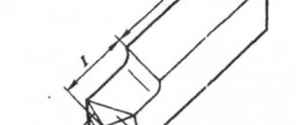
Therefore, in such cases it is often advantageous to work with wide finishing cutters made of high-speed steel (Fig. 42, a, b). They are used for processing rolling journals, gear shafts, etc., and at the same time roughness grades v6-v7 are achieved. The cutting modes when working with these cutters and the possible processing accuracy class are indicated in table. 27.
Table 27 Cutting conditions and processing accuracy when working with wide finishing cutters
In some cases, it is possible to work at a feed of 30-40 mm/rev. The cutting depth should be no less than 0.02 mm on the last pass and no more than 0.15 mm on the first pass.
Fig. 42. Wide finishing cutter (a) and diagram of its installation on the machine (b).
The length of the cutting edge of the cutter is assumed to be 80 - 100 mm. On both sides of it, at a length of approximately 10 mm, the intake and return cones are filled with the help of a whetstone (Fig. 42, a). The geometry of the cutter is selected depending on the properties of the steel being processed (Table 28).
Table 28 Geometry of a wide finishing cutter depending on the tensile strength of steel
The cutters are inserted with a tight fit into the socket of the spring holder (Fig. 42, b). The desired degree of elasticity of the holder is achieved using a wooden strip driven into the groove of the holder.
The cutting edge of the cutter is installed below the axis of the workpiece. This eliminates vibration and prevents the cutter from picking up. Moreover, as longevity shows; experience, higher quality of processing is ensured when working on the reverse rotation of the spindle (Fig. 42, b). It is recommended to use a liquid of the following composition as a lubricant: drying oil 60%, turpentine 30% and kerosene 10%.
Most often, finishing turning is performed with carbide cutters. Conventional cutters with an auxiliary lead angle are used on turning, rotary, boring and other machines. They are manufactured with T15K6 hard alloy plates. This hard alloy allows you to work at cutting speeds v = 100 - 250 m/min, depending on the properties of the steel being processed and some other factors. At this cutting speed, as is known, no build-up is formed on the cutter, and therefore, by choosing the appropriate feed rate, it is possible to confidently obtain a surface corresponding to class 6 according to GOST 2789-59, and in some cases, to class 7 cleanliness.
The use of T30K4 alloy makes it possible to increase the cutting speed by approximately 30-40% or more. Some high-speed turners increase the cutting speed to 400-500 m/min. T30K4 hard alloy has significantly greater wear resistance than T15K6 hard alloy. Therefore, the greatest effect from its use is observed in finishing turning of steel of increased hardness, especially with high requirements for cleanliness or precision of processing and when it is necessary to sharpen large surfaces with low feed without removing the cutter until the end of the pass.
Cutters with mineral-ceramic plates have so far found limited use. Like hard alloy T30K4, it is advisable to use ceramics in cases where it is necessary to obtain high precision and surface finish over a significant length, especially when processing cast iron.
Despite the high cutting speed allowed by hard alloys T15K6 and T30K4, conventional cutters with an auxiliary angle in the planar can provide high finishing productivity under v 6—v 7, since it is necessary to work at feeds of several tenths of a millimeter. Therefore, as in the entire mechanical engineering industry, carbide finishing cutters with an additional cutting edge parallel to the generatrix of the part are widely used in heavy engineering factories (Fig. 43, c). To obtain class 6-7 cleanliness, such cutters are used at t<=0.1 mm, s= 1 - 1.5 mm/rev, v = 150 - 200 m/min [42]. The length of the additional cutting edge is made from 1.5 to 2s. These cutters provide 2-3 times higher productivity compared to cutters without an additional cutting edge.
The highest labor productivity is achieved when working with wide carbide cutters (Fig. 43, a). Surfaces of several square meters can be turned with such cutters in 20-25 minutes. [44, 45]. These cutters can be used on lathes and rotary machines for turning rolling shafts, rollers, gears, bandages and other parts made of steel and bleached cast iron.
To obtain a surface of class 7-8, it is necessary to work at v > 150 m/min. The best results are achieved at v=250 - 300 m/min. However, practically feasible cutting speeds usually do not exceed 100 m/min, and therefore the surface roughness is no higher than class 6 cleanliness. But after a short sanding with sanding cloth, it is relatively easy to get a seventh grade.
The roughness of the machined surface is greatly influenced by: the ratio of the length of the straight section of the cutting edge l to the feed s (Fig. 43a), the cutting depth t, the correct installation of the cutter, the quality and geometry of its sharpening.
The higher the t/s ratio, the lower the roughness of the machined surface. When t/s = > 3, grades 7–8 are achieved, and when t/s = 2, grades 1.5–6 are achieved [6]. The cutting depth t should be taken based on the rigidity conditions of the machine-workpiece-cutter system. Typically t<=0.1 mm. The durability of wide cutters depends very little on the feed rate. Most often s = 5 - 10 mm/rev.
All irregularities in the cutting edge of a wide cutter are copied on the machined surface. Therefore, it is necessary to refine the front and rear surfaces to class 9-10 cleanliness. Blockages of the cutting edge are unacceptable. When installing the cutter, it is necessary to ensure that the section of the cutting edge at length l is strictly parallel to the forming part.
Experience shows that the size of the rake and back angles of a wide carbide cutter has virtually no effect on the microgeometry of the surface. It is recommended to make the rear angle 20°, and select the front angle depending on the hardness of the steel being processed in the range from -5 to + 10°. Moreover, for steel with hardness Hb => 300 = -5°, and for steel with hardness Hb<250 = +10°.
However, it should be borne in mind that when working with wide carbide cutters, vibrations often occur, which is why such cutters have not become widespread. The intensity of vibration increases greatly with increasing cutting edge length. Therefore, in cases where the vibration resistance of a conventional wide cutter (Fig. 43, a) is insufficient, wide cutters with a shorter cutting edge length (Fig. 43, b) or through cutters with an additional cutting edge (Fig. 43, c) are used.
In the vast majority of cases, the mounting holes of body parts are processed by boring on horizontal boring machines. Boring machines have less vibration resistance than turning machines and less rigidity of the machine-workpiece-tool system. Therefore, boring, as a rule, is carried out with conventional cutters with an angle
When determining the optimal geometric parameters of a boring cutter, it is necessary to take into account the reduction in the rake angle caused by installing the cutter above the center. In this regard, it is recommended for boring cutters to make the rake angle equal to 15° in the presence of a chamfer on the front surface f = 0.2 - 0.3 mm, located at a negative rake angle of 2°. The remaining geometric parameters of the cutter are recommended as follows:
Working with such cutters at t<= 0.25 mm, s = 0.1-:- 0.3 mm/rev and v= 150 -:- 250 m/min, it is possible to achieve the second class of accuracy and roughness corresponding to 6-7 class [44].
Skip to navigation
Surface roughness and its influence on the operation of machine parts
During the process of forming parts, roughness appears on their surface - a series of alternating protrusions and depressions of relatively small sizes.
Roughness can be a mark from a cutter or other cutting tool, a copy of the irregularities of molds or dies, and can appear as a result of vibrations that occur during cutting, as well as as a result of other factors.
The influence of roughness on the operation of machine parts is diverse:
- surface roughness can disrupt the nature of the mating of parts due to crushing or intense wear of the profile protrusions;
- in butt joints, due to significant roughness, the rigidity of the joints decreases;
- the roughness of the surface of the shafts destroys various types of seals in contact with them;
- irregularities, being stress concentrators, reduce the fatigue strength of parts;
- roughness affects the tightness of connections and the quality of galvanic and paint coatings;
- roughness affects the accuracy of measuring parts;
- metal corrosion occurs and spreads faster on roughly processed surfaces, etc.
Signs to indicate surface roughness depending on the type of processing
The main sign corresponding to the usual condition for normalizing roughness, when the method of surface formation is not regulated by the drawing.
A sign corresponding to the design requirement that the surface be formed by removing a layer of material, for example, by turning, grinding, polishing, etching, etc. (the specific type of processing may not be indicated).
A sign that meets the design requirement that the surface be formed without removing the surface layer of the material, for example, by casting, stamping, pressing (the specific type of surface formation may not be indicated).
The influence of roughness on the performance of parts
As mentioned earlier, in the process of giving a metal sheet the desired configuration, roughness remains at the impact sites - small depressions and ridges that affect the determination of the metal processing class. They can arise due to the unevenness of the cutting tool or vibrations that occur during work, remain as an imprint of unevenness on the stamp or mold itself, etc.
The presence of roughness in a part installed in a machine or other unit can lead to:
- incorrect mating of elements due to crushing of the material or accelerated wear of the protrusions of the part;
- decrease in joint strength, defects when applying paint and varnish and galvanic coatings;
- incorrect results of geometric measurements of an element;
- reducing the rigidity of butt joints;
- destruction of seals mated to shaft surfaces;
- reducing the fatigue strength of the element due to stress concentration in roughness;
- accelerated oxidation and deterioration of metal, etc.
Basic designations
The roughness of the surface under study is measured over tolerably small areas, and therefore the baselines are selected taking into account the parameter of reducing the influence of the wave-like state of the surface on changes in height parameters.
Irregularities on most surfaces arise due to the resulting deformations of the top layer of material during processing using various technologies. The outline of the profile is obtained during an examination using a diamond needle, and the imprint is recorded on a profilogram. The main parameters characterizing surface roughness have a specific letter designation, used in documentation, drawings and obtained when measuring parts (Rz, Ra, Rmax, Sm, Si, Tp).
To measure surface roughness, several defining parameters are used:
- Ra- denotes the value of the profile under study with possible deviation (arithmetic mean) and is measured in microns;
- Rz – denotes the height of the measured irregularities determined by 10 main points in microns;
- Rmax is the maximum permissible value of the height parameter.
Surface roughness designation
The step parameters Sm and Si and the reference length of the profile under study tp are also used. These parameters are indicated if it is necessary to take into account the operating conditions of the parts. In most cases, the universal indicator Ra is used for measurements, which gives the most complete characteristic taking into account all points of the profile. The value of the average height Rz is used when difficulties arise in determining Ra using instruments. Such characteristics affect the resistance and vibration resistance, as well as the electrical conductivity of materials.
The definition values of Ra and Rz are indicated in special tables and, if necessary, can be used when carrying out the necessary calculations. Typically, the determinant Ra is indicated without a numerical symbol; other indicators have the required symbol. According to current regulations (GOST), there is a scale that gives the values of surface roughness of various parts, which have a detailed breakdown into 14 special classes.
There is a direct relationship that determines the characteristics of the surface being processed; the higher the class indicator, the less important the height of the measured surface is and the better the quality of processing.
Surface roughness of parts when processed on a lathe
According to the formula in Fig. 4, by reverse recalculation, you can determine the value of the permissible feed, specifying the required value of the roughness index of the surface being processed and the recommended cutting conditions for the desired type of processing, however, the power coefficients and the hardness index NV are averaged reference data. Therefore, to ensure the accuracy of calculations based on this dependence, it is necessary each time for specific processing conditions to experimentally establish power coefficients and measure the hardness of the material being processed, which is an obstacle when using the formula in Fig. 4 in automated calculation mode.
Currently, there are other ways to ensure a given value of workpiece surface roughness. One of the methods is a method that includes registration of an acoustic emission signal, by which the value of the workpiece surface roughness is determined. According to the method, the acoustic emission signal is recorded and the roughness value of the workpiece is determined from it, wherein the spectral area of the acoustic emission signal is determined, and the magnitude of the roughness is judged by the ratio of the spectral areas of the recorded acoustic emission signal and a predetermined reference acoustic emission signal. Physically, the method is based on the fact that during the formation of the workpiece surface, acoustic pulses of a wide frequency range (0.1-1.0 MHz) occur, which reflect the processes of deformation and destruction of the material being processed. An integral characteristic of changes in the state of the workpiece surface, taking into account the simultaneous occurrence of deformation and destruction processes (formation of the machined surface of the workpiece), is the area of the acoustic emission spectrum.
There is a method for automatically ensuring the surface roughness of parts during machining of external surfaces based on dynamic monitoring using artificial neural networks. For this method, a control algorithm has been developed that ensures automatic achievement of a given value of microroughness of the treated surface. The proposed algorithm and its software implementation allow, based on the requirements of the drawing (Rα, S