History of lathes in the Soviet Union
The development of machine tool industry in the USSR began after the October Revolution. After the discovery of high-speed steel and hard alloys, powerful units began to be produced. 1A62 is one of the first machines that began to be used in mass and serial production. Released.
In 1956, it was replaced by an improved modification 1K62 with greater power and a range of modes. Later, engineers continued to work on improving the design of the units. To this day, enterprises operate 16K20, DIP 200, DIP 300 and other models.
Application area
Lathes are used for internal and external machining of cylindrical surfaces. Shafts, bushings, flanges, pulleys, couplings and other parts can be manufactured.
The workpiece is installed in a chuck, which rotates together with the spindle at specified speeds. The cutting tool makes a translational movement. Due to this, the workpiece acquires the desired shape and size.
Types of operations:
- End processing.
- Grinding the outer surface to a given diameter.
- Drilling and boring holes.
- Grooving.
- Cutting internal and external threads.
- Reaming and countersinking.
Lathe design
The main nodes are:
- The bed is a supporting structure on which all components are located.
- Headstock - it contains the spindle, which rotates with the part, and the gearbox.
- Tailstock - additionally secures the part during processing in the centers. The quill is used to attach a cutting tool (drill, reamer).
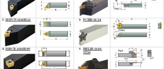
- Caliper - carries a tool holder into which turning tools are attached. Moves in the transverse and longitudinal direction at a given speed.
- Feed box - provides movement from the lead screw or shaft to the caliper.
Important!
On most models, the main components are unified.
SPECIAL MECHANISMS
Price: Check
Screw-cutting lathe mod. 1N65 with RMC-3000 mm. (manufactured by the Ryazan Machine Tool Plant) is designed for processing a variety of parts and workpieces (rotation bodies) from different materials up to 2800 mm. length and up to 1000 mm. diameter, in conditions of single and small-scale production. It has an increased cylindrical spindle diameter of 128 mm. The machine can perform external and internal turning, including turning cones, boring, drilling, reaming, cutting external and internal threads, etc. Cutting by type of threads: metric, modular, inch, pitch.
The technical characteristics and rigidity of the design of the machine bed, carriage, and spindle allow full use of the capabilities of working at high cutting speeds using cutters made of high-speed steel or equipped with hard alloy plates when processing parts made of ferrous and non-ferrous metals, and allow obtaining the necessary processing accuracy. 2-prism guides of the frame, in combination with the high reliability of other components, ensure a long service life of the machine while maintaining the original accuracy. The machine support has a mechanical movement of the upper part, which allows turning cones. Changing the feed rates and adjusting the pitch of the thread being cut is carried out by switching the gears of the feed box and adjusting the set of interchangeable gears. The support has the ability to accelerate movements in the longitudinal and transverse directions, which is carried out by an individual electric motor. The closed-type feed box has a high rigidity of the kinematic chain and ensures threading and switching of various feed rates. Changing the spindle speed and caliper feed speed is carried out by switching the gears of the gearbox and feedbox using handles. The tailstock is moved and the quill is extended manually. For processing workpieces and long parts, fixed and movable steady rests can be supplied in the kit.
| Specifications | 1N65-3000 |
| The largest outer diameter of the workpiece, mm: | |
| above the bed, mm | 1000 |
| above the caliper, mm | 650 |
| Maximum length of the workpiece, mm | 2800 |
| Diameter of a cylindrical hole in the spindle (not less), mm | 128 |
| Spindle end according to GOST 12595-72 | 2-15M |
| Height of the cutter installed in the tool holder, mm | 59 |
| Number of spindle speeds | 24 |
| Spindle speed, rpm | 5-500 |
| Number of feeds longitudinal/transverse | 40/40 |
| Feed, mm/rev: | |
| longitudinal | 0,10…3,05 |
| transverse | 0,035…1,04 |
| Maximum cutting force allowed by the feed mechanism, kgf: | |
| longitudinal | 1200 |
| transverse | 780 |
| Thread pitch | |
| metric, mm | 1…120 |
| modular, module | 0,5…30 |
| inch, threads per inch | 28…1/4 |
| Maximum mass of the processed product, kg | 5000 |
| Dimensions, mm: | |
| length | 6140 |
| width | 2200 |
| height | 1770 |
| Machine weight, kg | 12850 |
Write to us
Return to home page
Old Soviet models of wood and metal machines
Soviet equipment is still in use in production. Some people fundamentally prefer to equip their home workshops with units from the USSR.
Important!
It is sometimes difficult to find equipment or components for Soviet equipment in case of breakdown.
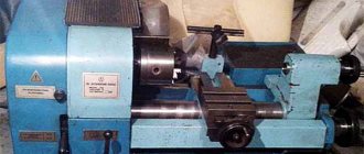
Screw-cutting lathe IT-1M
The lightweight machine was intended for gaining practice in workshops. Allows you to process cylindrical workpieces from the outside, drill and boring, and cut threads. Currently out of production.
Description of the design of the main components of the 1M65 screw-cutting lathe
bed
The bed is the basic assembly unit on which all other assembly units and mechanisms of the machine are mounted.
On the top of the frame there are three prismatic guides, of which the front and rear are the base of the carriage, and the middle one is the base of the tailstock.
Inside the frame there are inclined hatches for removing chips and coolant in the direction opposite to the workplace.
Under the left head part of the frame there are niches, in one of which the main drive electric motor is mounted, and in the other - an electric cooling pump with a coolant reservoir. The trough for collecting coolant is made monolithic with the frame body.
On the right side of the frame, on the front wall, a bracket is mounted with supports for the lead screw and lead shaft built into it.
To prevent sagging of the lead screw and the lead shaft, the machine with RMC = 5000 mm has two suspensions.
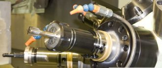
Headstock
Spindle head of screw-cutting lathe 1m65
Spindle head of screw-cutting lathe 1m65
The front headstock is installed on the left head part of the frame, fixed with pins and secured with bolts.
The following are mounted in the spindle head housing:
- electromagnetic clutch for spindle braking
- spindle unit
- step increase link 8 times
- mechanism for changing the direction of movement of the carriage or threading
- spindle speed adjustment mechanism
- forks for moving gear blocks
- shift knobs and other parts
- Lubrication system
- electrical cabinet
The spindle is mounted on three rolling bearings, of which the front and rear are adjustable.
Tailstock
The rear headstock moves along the frame guides from the manual gearbox by rotating the roller.
A rotating spindle is built into the headstock quill, the front support bearings of which are adjusted using nuts.
The tailstock spindle has a slot for the legs of the tail cutting tool.
Caliper
The support of the cross design has longitudinal movement along with the carriage along the frame guides, and transverse movement along the carriage guides.
Both movements are carried out mechanically using a cross switch and manually by rotating the flywheel and carriage handle.
The cutting slide, carrying a four-position tool holder, moves manually and mechanically along the guides of the rotating part, which can be rotated around its axis at any angle.
The carriage of machines with a digital display device is equipped with a linear displacement transducer, which is connected to the transverse displacement screw using a bellows coupling.
The lateral movement can be counted using the dial and the DRO display.
Apron
The machine apron is of a closed type with a removable front cover. The movement of the caliper group is transmitted by the apron mechanism from the drive shaft or lead screw.
Due to the presence of four electromagnetic clutches in the apron, control of the mechanical movement of the caliper group is concentrated in one handle, and the direction of activation of the handle coincides with the direction of feed.
It is possible to enable rapid movement of the caliper in the direction of tilting the control handle.
Thanks to the overrunning clutch built into the apron, high speed can be activated when the feed is on. The rapid speed electric motor is installed on the apron.
A safety clutch mechanism is mounted in the apron, which prevents the machine from breaking due to overload.
Gearbox
Closed feed box with removable front cover.
The feed box mechanism allows you to get the first row of feeds and all the threads cut on the machine, without having to change the settings of the replacement gears.
To obtain the second row of feeds, replaceable wheels are installed: a = 42, b = c = 126.
Machine equipment
The machine includes a four-jaw non-self-centering chuck with a diameter of 1000 mm.
For processing non-rigid parts, the machine is equipped with two steady rests - movable and fixed.
The movable rest is mounted on the carriage and supports the part directly near the cutter. The breadcrumb coverage diameter is provided in the range from 70 to 250 mm.
The stationary steady rest is installed on the frame guides anywhere and secured with a bolt using a clamp.
It is equipped with crackers and rollers, which are installed depending on the processing conditions.
The diameter of coverage of the workpiece in the stationary steady rest is provided in the range from 70 to 380 mm.