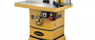
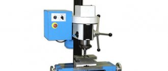
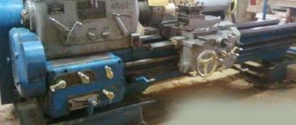
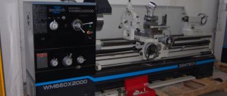
A milling machine is equipment for processing shaped and flat metal workpieces with screw and straight generatrices. Using machines, you can make grooves, grooves, holes, apply internal and external threads, and also perform a number of other technological operations. Depending on the direction of movement of the working body, horizontal and vertical milling machines are distinguished. The main components and mechanisms in both types of equipment are the same, except for the support and trunk, which are not present in the vertical modifications.
bed
All the main components and mechanisms of the milling machine are attached to the part. The spindle, gearbox, and motors are hidden inside the structure, and the remaining units are mounted on external surfaces. In the upper part of the frame there can be horizontal guides for moving the trunk, and on the front wall - vertical guides for the console or spindle head. The part is reinforced from the inside with stiffening ribs. The frame can be cast or welded. The first option is considered more reliable and durable, but welding produces more complex structures.
Cantilever milling machines produced in the USSR and CIS
| Series | Size | Manufacturer | Year | Model |
| 6 | 2 | SFFS | 1932 | 682 |
| 6B | 0 | |||
| 1 | ||||
| 2 | SFFS | 1937 | 6B12, 6B82, 6B82G | |
| 3 | ||||
| 6K | 0 | |||
| 1 | DZFS | 6K11, 6K81, 6K81G, 6K81SH | ||
| 2 | SFFS | 6K12, 6K82, 6K82G, 6K82SH | ||
| 3 | SFFS | 6K13P, 6K83, 6K83G, 6K83SH | ||
| 6H | 0 | Zalgiris | 1969 | 6N10, 6N80, 6N80G, 6N80Sh |
| 1 | DZFS | 1970 | 6N11, 6N81, 6N81G, 6N81A, 6N81D | |
| 2 | SFFS | 1951 | 6N12, 6N82, 6N82G | |
| 3 | GZFS, VSW | 1951 | 6N13, 6N13F3, 6N83, 6N83G, 6N13GA | |
| 6M | 0 | Zalgiris | 6M10, 6M80, 6M80G, 6M80Sh | |
| 1 | DZFS | 1971 | 6M11, 6M11K, 6M81, 6M81G, 6M81Sh, 6M81Sh-1, 6M81Sh-1F1, 6M81ShF2 | |
| 2 | SFFS | 1961 | 6M12P, 6M12PB, 6M82, 6M82G, 6M82GB, 6M82Sh | |
| 3 | SFFS | 1961 | 6M13P, 6M13PB, 6M83, 6M83G, 6M83Sh | |
| 6Р | 0 | Zalgiris | 1973 | 6Р10, 6Р80, 6Р80Г, 6Р80Ш |
| 1 | DZFS | 6Р11, 6Р11К, 6Р11Ф3, 6Р81, 6Р81Г, 6Р81Ш | ||
| 2 | SFFS | 1972 | 6Р12, 6Р12К, 6Р82, 6Р82Г, 6Р82Ш | |
| 3 | GZFS, VSW | 1972 | 6Р13, 6Р13Б, 6Р13Ф3, 6Р13Ф3-3, 6Р83, 6Р83Г, 6Р83Ш | |
| 6T | 0 | Zalgiris | 1986 | 6Т10, 6Т80, 6Т80Ш |
| 1 | ||||
| 2 | SFFS | 1985 | 6T12, 6T82, 6T82G, 6T82Sh | |
| 3 | SFFS | 1985 | 6Т13, 6Т83, 6Т83Г, 6Т83Ш | |
| 6D | 0 | DZFS | 1987 | 6D10, 6DM80Sh |
| 1 | DZFS | 1990 | 6D81, 6D81, 6D81G, 6D81SH | |
| 2 | DZFS | 6D12, 6D12F20, 6D12F3, 6D82, 6D82G, 6D82SH | ||
| 3 | DZFS | 6DM83SH |
The main manufacturers of milling machines in the USSR and Russia:
VSW - Votkinsk Machine-Building Plant. Currently - Votkinsk Plant, JSC
GZFS - Gorky Milling Machine Plant. Currently - ZFS Milling Machines Plant, LLC
DZFS - Dmitrov Milling Machine Plant. Currently - Dmitrov milling machine plant DZFS, LLC
UZTS - Ulyanovsk plant of heavy and unique machine tools UZTS. Currently - Ulyanovsk Plant of Heavy and Unique Machine Tools UZTS, LLC
VSZ - Voronezh Machine Tool Plant.
Zalgiris – Vilnius Machine Tool Plant
Trunk (creeper)
This unit is found on horizontal and universal type milling machines and is rarely found on CNC machines. The main purpose of the trunk is correct installation and reliable support of the mandrel . The mechanism is mounted on horizontal guides of the frame and allows for changes in reach, that is, the distance to the mirrors. When processing massive parts, when chips of a large cross-section are obtained, special supports are used for additional fixation of the workpiece, which form a connection between the trunk and the console.
Selection principles
When choosing equipment you need to pay attention to some features:
- First of all, you need to evaluate the dimensions of the equipment. It should be freely located in the room and have enough space on different sides.
- The material from which the structure and frame are made. If hard materials will be processed on the machine, the frame must be made of metal.
- Engine power. The most important parameter when choosing. The more powerful the electric motor, the harder the materials can be made.
- Cooling. To ensure that the cutter does not overheat and the surface being processed does not become unusable, it is necessary to choose equipment with cooling. Water and air systems are available for sale. For water ones, you need to think about how to arrange the hoses and container for supplying liquid. Air systems need to be cleaned of dust that accumulates on cleaning filters.
- Control system. It is better to choose a model with the ability to adjust the spindle speed.
There is no point in purchasing expensive equipment if it will not be used regularly. There are models of machines for professionals and amateurs. There are also machines designed for large enterprises and their own workshops.
Equipment for the machine
Console
The part is cast from cast iron and installed on the vertical guides of the frame. When moving, the console, in turn, carries horizontal guides for the slide. To support the unit, there is a stand with a telescopic screw that allows you to adjust the height. The operation of the equipment largely depends on the rigidity of the console and the accuracy of its guides. Supports are attached to the element using two bolts, which ensure the stability of the entire system during operation. On non-cantilever machines, vertical movement is organized by the spindle head along vertical guides
Main parts of drilling machine
A drilling machine is necessary to create through and blind holes. Drills are used for this. A special cutting tool removes chips from the workpiece being processed.
Names of the basic components of the drilling machine:
- Vertical column (bed).
It is a support on which all the main components of the machine are placed. - Electric motor.
Necessary for starting the spindle head. Can be phase or asynchronous. Drilling begins only after the engine reaches the design rotation speed. - Drilling head.
This is the main block. The drilling head is equipped with a gearbox with a mechanism for changing the gear frequency, a vertical feed mechanism with a handle, a dial for precise feeding, and a spindle with a chuck. - Gearbox and feed shift knob.
Allows you to change the speed of working movements. - Manual feed steering wheel.
Responsible for manual vertical feed. - Gearbox and feed shift knob.
Allows you to change the speed of working movements. - Processing depth control dial.
This ring head with a marked scale is necessary for adjusting the vertical feed. The limb is used for drilling holes of a certain depth. The details indicate the scale division price. - Spindle.
The part is necessary to secure the chuck and transmit rotational motion to the drill. Can move vertically along a guide in the drill head. - Coolant supply nozzle.
It is part of the cooling mechanism for the workpiece and drill. As soon as the pump is turned on, a stream of lubricant and cooling liquid from the nozzle enters the processing area. - Table.
Necessary for securing the workpiece. There are grooves in the surface for securing gripping devices: clamps, vices, etc. - Table lift handle.
Allows you to change the table level, bring the workpiece to the spindle or, conversely, move it away from it. - Foundation slab.
It is the base of the machine. It is a massive, stable structure with holes for bolts. - Electrical equipment cabinet.
Equipped with electrical circuits, control relays, and safety elements. Modern machines have a workflow automation control panel.
Modern drilling machines differ in design and functionality. The main task facing their manufacturers is to automate work processes as much as possible and expand the technological capabilities of the units.
The main tools of a drilling machine are chucks. They come in cam, collet, and thread-cutting types. Internal surfaces of large diameters or intricate configurations are processed with boring heads with manual and automatic feed. They are also used to bore internal grooves and stepped holes, which require high precision and surface finish.
To secure the workpiece being processed, machine vices of different sizes, tilting tables, tables with longitudinal-transverse movement, dividing heads and other devices are used. All of them help to securely fasten products in a position that allows them to be processed with minimal deviation from the requirements of the drawing.
Table
The main working element of a milling machine, which moves on a slide. On the surface of the table there are clamping and other fixing devices for firmly securing workpieces. For this purpose, the part has longitudinal grooves. The joint operation of the table, console and slide ensures the supply of the workpiece to the cutter. Movement in longitudinal, vertical and transverse directions is possible. Typical equipment usually has manual and mechanical feed. The use of one method or another depends on the tasks:
- For idle runs and installation movements of the table, a manual, mechanical method is used
- For working feed, mechanized feed is most often used.
Additionally, the possibility of rapid movement of the table is provided, the so-called rapid movement in all three directions. The movement is carried out at a constant speed (most of the machines are equipped with an additional clutch or high-speed motor), while the working feeds have a multi-stage shift box. The operator independently selects the mode depending on the material of the workpiece and cutter, as well as the type of processing.
Main technical characteristics
The main difference between milling operations and the equipment intended for this is the number of coordinates in which the surface is simultaneously processed. The following parameters are used to describe the technological properties of milling machines:
- accuracy of operations;
- maximum movements along coordinates;
- feed modes and speeds;
- cutting and loading modes;
- availability of mechanized tool change;
- possibility of installing additional equipment;
- power consumption.
Each of these characteristics affects the overall design of the machine. The final parameters combine a compromise between the main characteristics.
Electric motors
Main movement - rotates the spindle, located in the spindle headstock or column.
Working feeds, rapid movements - fixed to the feed box
Console movements - mounted on the console, if available
Coolant supply. Located in a tray or chip collector. Other auxiliary equipment - located at locations selected by the manufacturer.
Gearbox
By rotating the gears and switching them, the force from the electric motor is transmitted to the spindle. The mechanism also allows you to adjust the speed of the cutting tool.
Gearbox
The purpose of the unit is to change the table feed speed in all three directions.
Hello student
Milling machines are divided into: 1) horizontal milling, universal milling, 3) vertical milling and 4) copy milling. Let's look at their designs.
Horizontal milling machine.
Machines of this type are used in mechanical and tool shops. In fig. 486 shows a general view of a horizontal milling machine. Mandrel 1 is used to secure the cutter to the spindle. The part is fixed on table 2.
In fig. 487 shows the kinematic diagram of a horizontal milling machine. Spindle 1 receives rotation from pulley 2 and can work with and without overdrive 3. Table 4 receives translational motion (feed movement) from spindle 1 through feed box 5, universal joint 6, worm 7 and worm gear 8, rigidly mounted on the screw of the longitudinal self-propelled table.
Universal milling machine.
Of all types of milling machines, universal milling machines are the most widely used; They are used in mechanical repair and tool shops, as well as in factories with individual and small-scale production. A distinctive feature of these machines is the design of the table mechanism, which allows the table to rotate about a vertical axis in a horizontal plane. Rotating the table in a horizontal plane (done manually) is necessary when milling spiral grooves (twist drill, etc.). In fig. 488 shows a general view of a universal milling machine. Mandrel 1 is used to install cutters; The parts to be processed are fixed on table 2.
In fig. 489 shows the kinematic diagram of a universal milling machine. In this machine, the milling cutter, mounted on spindle 1, receives rotation from electric motor 2 through a belt drive 3 and gearbox 4. Table 5 receives feed movement from shaft 6 through a system of bevel gears and feedbox 7. Table 5 can have three different directions of movement feed: 1) longitudinal feed is carried out by a lead screw 8, which receives rotation from a bevel gear 9; 2) vertical feed is carried out by screw 10 through a bevel gear 11, rigidly mounted on screw 10; when this screw rotates, it, moving along nut 12, lowers or raises the table; 3) transverse feed is achieved by screw 13, along which a nut 14 rigidly connected to the table moves.
Vertical milling machine.
In vertical milling machines, the spindle occupies a vertical position; The main movement drive is similar to the drive of vertical drilling machines. The feed in these machines can be longitudinal, transverse and vertical.
These machines are mainly used for milling keyways, JL slots, dovetail slots, etc.
In fig. 490 shows a general view of a vertical milling machine. The part is fixed on table 1, and the cutter is mounted on spindle 2.
In fig. 491 shows the kinematic diagram of a vertical milling machine. According to the diagram, the spindle receives rotation from the electric motor E1 through pulleys 1 and 2 and then through gears located on shafts I, II, III, IV, V, VI. The feed in this machine is carried out from another electric motor E2 through the feed box 3. The longitudinal movement of the table (feed) is made by screw 4, transverse - by screw 5 and vertical - by screw 6, semi
causing movement through the corresponding gear wheels of the feed box, similar to how this is done in a universal milling machine (see kinematic diagram in Fig. 489.
Longitudinal milling machine.
Longitudinal milling machines are used for processing long and wide planes, as well as shaped profiles on large parts, for example, the bed of various machines. These machines are characterized by high productivity, as they can work with several cutters simultaneously. In fig. 492 shows a general view of a longitudinal milling machine. The table with the part attached to it can move along the frame guides; There are two milling heads on the vertical posts that can move in the vertical direction.
Copy milling machine.
Copy-milling machines are used to process various shaped surfaces. In fig. 493 shows a diagram of the design of a copy-milling machine. A copier 2 and a workpiece 3 are mounted on a rotating table 1. The principle of operation of the machine is that the copier 2 is continuously pressed against the roller 4 under the action of a load not shown in the drawing, and forces the table on which the part is mounted to describe a trajectory similar to a line the outline of the copier, and cutter 5 consequently processes the surface, the outline of which will also be similar to the outline of the copier.
Download abstract: You do not have access to download files from our server. HOW TO DOWNLOAD HERE
Archive password: privetstudent.com
Manufacturing technology
In order not to buy a powerful machine for mass production, you can assemble homemade equipment. On the Internet there are drawings of structures and mechanisms for metal processing that are made by hand.
First of all, you need to prepare materials and tools. It is advisable to make the frame from metal corners or profiles. The metal is joined by welding. The working surface is made of a single sheet of metal more than 3 mm thick. An engraver, drill or drill is used as a motor. Their power is sufficient for tabletop machines through which soft woods and thin sheet metal will pass. To secure the working part, you need to build a frame. It is made from plywood, chipboard, MDF, durable plastic. Fasteners are self-tapping screws, bolts, nuts. It is necessary to attach guides to the structure along which the working part with the cutter will move.
A milling machine is an indispensable element of enterprises engaged in metalworking. If there is a lack of funds, you can make a tabletop mechanism for processing wood, plastic and sheet metal.
