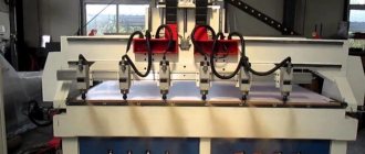
Machine 3b151 technical characteristics
Care and Maintenance Guide. The cylindrical grinding machine model 3B151 is designed for external grinding of cylindrical products and flat cones.
The following types of processing can be performed on the machine: — Longitudinal and milling grinding with manual control; — Longitudinal grinding with automatic transverse feed, carried out when the table is reversed; — Plunge grinding to the stop with a semi-automatic operation cycle; The machine of this model provides the ability to install active control devices, which are supplied with it by special order and for an additional fee. The machine is mainly designed to work in serial and mass production, but can also be used in individual production.
The modification of the machine does not have a hydraulic plunge mechanism. It is designed mainly for longitudinal grinding and is equipped with an automatic transverse feed mechanism, which occurs when the table is reversed. It can also perform plunge-cut and longitudinal grinding with manual transverse feed.
Model 3b151 machines are designed for external grinding of cylindrical and flat conical surfaces in mass production conditions.
Composition: General view
Software: KOMPAS-3D 15
Posted by vindjj
Date of: 2019-03-05
Views: 105
Add to favorites
Key Features
There are quite a few different designs of cylindrical grinding machines that allow processing of cylindrical and conical surfaces. The version with a 3M151 grinding head is used quite often; the passport indicates all the important technical characteristics, and the diagram also indicates important points about the location of structural elements.
Download the passport of the grinding machine 3M151
Cylindrical grinding machine model 3M151 is used for processing the outer cylindrical surface. Shaft-type products are often processed on the 3M151 machine. In this case, conical workpieces can also be processed while the grinding headstock is displaced. The machine passport contains information about how conical the surface can be. It is worth noting that the cylindrical grinding machine model 3M151 has increased accuracy. When using it, you can carry out the following types of work:
- The design scheme makes it possible to carry out longitudinal and transverse grinding using manual feed. the passport indicates the maximum longitudinal and transverse manual feed;
- model 3m151 can be used for plunge-cut and longitudinal grinding in a semi-automatic operating cycle;
- Some versions have a system for entering a workpiece processing program; the work is carried out automatically.
Production of the 3M151 model began in the last millennium. Information from the passport and diagram determines the possibility of using the 3M151 model in small-scale, serial and large-scale production. Over many years of using the equipment, it was noted that the installed grinding head allows metal to be removed from a conical surface with great accuracy.
More drawings and projects on this topic:
Software: SolidWorks 14
Composition: 3D Assembly
Software: AutoCAD 2014 SP1
Composition: General view of the universal cylindrical grinding machine model ZB12, schematic diagram of the universal cylindrical grinding machine model ZB12
Software: Creo Elements/Pro 2.0
Composition: 3D model
Software: Creo Elements/Pro 2.0
Composition: 3D model
Software: KOMPAS-3D V13
Contents: Electrical circuit diagram drawing of the 3S130V universal cylindrical grinding machine.
Posted by vindjj
Date of: 2019-03-05
Views: 105
Add to favorites
Electrical circuit diagram of the 3A161 machine
Electrical diagram of cylindrical grinding machine 3a161
The machines are equipped with seven electric drives: grinding wheel, hydraulic pump, cooling pump, grinding head spindle bearing lubrication pump, bed guide lubrication pump, magnetic separator and workpiece.
All electric drives, except for the product drive, have three-phase asynchronous electric motors with a squirrel-cage rotor. The electric drive of the product has a DC electric motor with a parallel field winding, which receives power from a block of magnetic amplifiers and rectifiers.
The speed of the electric motor driving the product can be steplessly adjusted from 250 to 2500 rpm.
The machines are equipped with local lighting from a reduced voltage of 36 V.
A voltage of 127 V is provided for control circuits.
The local lighting and control circuits are powered through a step-down transformer.
The machines are produced for power supply from a three-phase alternating current network with a voltage of 380 V, 50 Hz.
By agreement with the manufacturer, machines can be manufactured for other supply voltages, local lighting and control circuits.
The control station is attached to the machine bed.
NO COMMENTS YET
Leave a comment, review of the work, complaint (specific criticism only) or simply thank the author.
Archive or drawing won't open? Read before writing a comment.
Please login to add comments.
9.7 Cylindrical grinding machine model 3B151
Largest dimensions of the installed product, mm:
Largest grinding dimensions, mm
Morse taper center of the headstock:
Grinding wheel size (outer diameter × height × hole diameter), mm:
Electric motor power, kW:
grinding wheel drive
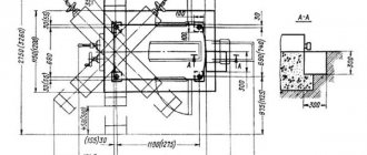
Machine dimensions, mm:
9.8 Universal sharpening machine model 3D642E
The largest dimensions of the workpiece to be processed, installed in the centers:
Angle of rotation of the table in the horizontal plane of the table, 0
Moving the grinding head:
Similar works
. safety requirements; The selection of auxiliary devices is carried out depending on the type, shape, weight, material and size of parts, technological schemes of equipment and serial production. Screw-cutting lathes are used to process parts such as bodies of revolution. When automating production, it is necessary to use CNC machines, therefore, to ensure this condition.
. IN THE FIELD OF PRODUCTION PREPARATION. Savings from reducing the cost of design are determined by the formula: E' = (C1 - C2) * A2, where C1 is the cost of designing a structural element or developing one technological process using the existing design method, rub.; C2 is the cost of designing a structural element or developing one technological process at .
. Calculations have shown that significant differences in the duration of assembly and welding operations at individual robotic complexes make it impractical to create an automatic drum welding line with a unified control system. Therefore, it was decided to organize a robotic technological section, combining individual robotic complexes with a common mechanized transport system with storage devices between them. For left and right.
. the auto operator is strictly synchronized with the operation of the equipment being serviced. Automatic devices can have mechanical, magnetic, electromagnetic, or vacuum gripping devices. 11. Transport and warehouse systems of automated production. Requirements, main types and examples of designs Transport devices of automated systems are designed to move parts from position to position.
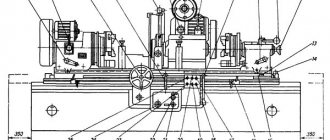
List and designation of components of the 3A161 grinding machine
- 1. Machine bed
- 2. Grinding head
- 3. Hydraulic control
- 4. Mechanism for manual movement of the table
- 5. Cross feed mechanism
- 6. Headstock
- 7. Tailstock
- 8. Oil line*
- 83. Grinding wheel housing
- 85. Cooling
- 87. Lunette
- 89. Device for dressing the grinding wheel
- 91. Fencing
- 92. Mechanism for quick supply of the grinding head (only on machines models 3B151 and 3B161)*
- 92. Mechanism for quick approach and insertion (only on machines models 3a151 and 3a161)*
- 94. Accessories*
- 95. Electrical equipment, control panel
- SHU-270. Grinding wheel flange*
- SHU-297. Mechanism for balancing the grinding wheel
- SHU-965. Correct device*
* Groups and nodes marked with an asterisk are not shown in the figure.
Cylindrical grinding machine 3b151 technical characteristics
The machines are designed for external grinding of cylindrical products and flat cones.
The following types of processing can be performed on machines of models ZA151 and ZA161:
1) longitudinal and plunge grinding with manual control;
2) longitudinal grinding with automatic transverse feed, carried out when the table is reversed;
3) plunge grinding to the stop during a semi-automatic operation cycle.
On the machines of these models, it is possible to install active control devices, which are supplied with them on special order and for an additional fee. Machines of the ZA151 and ZA161 models are designed primarily for operation in serial and mass production conditions, but can also be used in individual production. Machines of models ZB151 and ZB161 do not have a hydraulic plunge mechanism. They are designed mainly for longitudinal grinding and are equipped with an automatic transverse feed mechanism, which occurs when the table is reversed. They can also be used for plunge-cut and longitudinal grinding with manual transverse feed. Machines of models ZB151 and ZB161 are designed to work in conditions of serial and single production.
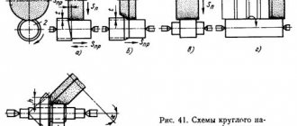
Hydrokinematic scheme
Through a series of kinematic chains and a hydraulic system, the following movements are carried out in the machine:
1. Rotate the spindle of the grinding head.
2. Rotation of the product.
3. Manual and automatic cross feed (machines of models ZA151 and ZA161 have two types of automatic cross feed - continuous plunge feed and periodic feed, carried out when the table is reversed;
machines models ZB151 and ZB 161 do not have automatic plunge feed).
4. Manual and hydraulic movement of the table.
5. Fast hydraulic supply and removal of the grinding headstock.
6. Hydraulic outlet of the tailstock quill. The kinematic chains of the main movement, rotation of the product, manual transverse feed and manual movement of the table are clear from the attached diagrams (see Fig. 21 and 22) and therefore their description is not given. This section describes the design features and operating principles of individual machine components. The design and operation of the hydraulic system are described in the section “Hydraulic drive of machines”.
Hydraulic drive of the machine
The hydraulic drive of the machine performs the following functions: longitudinal reversible movement of the table at operating speed or at straightening speed; speed-controlled table movement with the grinding head retracted; oscillating movement of the table; quick approach and removal of the grinding head; specified movement of the grinding head; retraction of the tailstock quill with the grinding head retracted; blocking the mechanism for manual movement of the table; continuous feed of the grinding head until the wheel touches the workpiece; transverse feeds of the grinding head, continuous during plunge grinding and periodic during longitudinal grinding; finishing microfeed (jog microfeed); automatic retraction of the headstock after reaching a specified size; sending commands to the electric counter of table moves during nursing; movement of the support and carriage when editing on a smooth or stepped copier; feeding of the diamond pencil of the dressing device; compensation for allowance removed during editing; moving the bracket of the measuring control device; moving the cylinders of the wide-range measuring device; supply of lubricant to the bearings of the grinding headstock spindle, table guides and cross feed screw support. .
Hydraulic drives are widely used in grinding machines. Mineral oils (Industrial 12 and 20) are used as working fluids. The hydraulic drive of the cylindrical grinding machine table (Fig. 12) works like this: oil from reservoir 1, through the suction pipeline of pump 3 and check valve 5, enters the hydraulic distributor (spool) 6, and then (through the pipeline into the left cavity of the hydraulic cylinder 10, the double-sided rod of which is connected to table 11. The table moves from left to right.In this case, the oil from the right cavity of the hydraulic cylinder returns through pipeline 9 through hydraulic throttle 4 to reservoir 1. To move the table from right to left, solenoid 7 moves hydraulic distributor 6. Safety valve 2 serves to release oil when the pressure in the system increases. To supply fluid (to the hydraulic system of a grinding machine), gear, vane and piston pumps are used.To control and regulate the amount and pressure of oil, various control and regulating devices, check valves, safety valves, pressure reducing valves, throttles, and speed controllers are used.
Purpose of the metal machine 3B151P
The semi-automatic machine is designed for external grinding of cylindrical and flat conical surfaces in mass production conditions. Grinding is carried out in fixed centers
Technical characteristics of the machine 3B151P
We offer to buy new or overhauled analogues of equipment such as 3B151P cylindrical grinding machine at a competitive price. You can select the appropriate model yourself on our website in the CATALOG section, or by consulting the sales department of our company.
The sale of analogues of the machine model 3B151P is made with 100% prepayment if the equipment is in stock and 50% prepayment when the machine is put into production at the manufacturer and payment of the remaining 50% after notification of its readiness for shipment. Another jointly agreed upon payment procedure is possible.
The warranty for products similar to the product - Cylindrical grinding machine 3B151P is:
- new machines - 12 months,
- after major repairs - 6-12 months.
Manufacturers reserve the right to change the standard configuration and place of production of equipment without notice!
We draw your attention to the fact that the prices indicated on our website are not a public offer, and check the cost of the equipment with our sales managers of machine tools and forging equipment!
If you need to buy a 3B151P cylindrical grinding machine, call:
in Moscow in St. Petersburg in Minsk +375 (17) 246-40-09 in Ekaterinburg in Novosibirsk in Chelyabinsk in Tyumen +7 (3452) 514-886
in Nizhny Novgorod in Samara in Perm in Rostov-on-Don in Voronezh in Krasnoyarsk
in Nur-Sultan;
in Abakan, Almetyevsk, Arkhangelsk, Astrakhan, Barnaul, Belgorod, Blagoveshchensk, Bryansk, Vladivostok, Vladimir, Volgograd, Vologda, Ivanovo, Izhevsk, Irkutsk, Yoshkar-Ola, Kazan, Kaluga, Kemerovo, Kirov, Krasnodar, Krasnoyarsk, Kurgan, Kursk , Kyzyl, Lipetsk, Magadan, Magnitogorsk, Maikop, Murmansk, Naberezhnye Chelny, Nizhnekamsk, Veliky Novgorod, Novokuznetsk, Novorossiysk, Novy Urengoy, Norilsk, Omsk, Orel, Orenburg, Penza, Perm, Petrozavodsk, Pskov, Ryazan, Saransk, Saratov, Sevastopol, Simferopol, Smolensk, Syktyvkar, Tambov, Tver, Tomsk, Tula, Ulan-Ude, Ulyanovsk, Ufa, Khabarovsk, Cheboksary, Chita, Elista, Yakutsk, Yaroslavl and other cities
Toll-free number throughout Russia.
In the CIS countries - Belarus, Kazakhstan, Turkmenistan, Uzbekistan, Ukraine, Tajikistan, Moldova, Azerbaijan, Kyrgyzstan, Armenia in the cities of Nur-Sultan, Bishkek, Baku, Yerevan, Minsk, Ashgabat, Chisinau, Dushanbe, Tashkent, Kiev and others for purchase equipment such as Cylindrical grinding machine 3B151P, call any convenient number listed on our website, or leave your contacts under the ORDER A CALL button at the top of the site - we will call you back.
Description of the circuit diagram
To start the machine, you must turn on the automatic switch AB (Fig. 1) and operate the CNG button. In this case, the electric motors of the pumps will turn on: hydraulics G, lubrication of the spindle bearings of the grinding headstock C, lubrication of the frame guides 1C.
After making sure that there is oil circulation in two transparent caps located on the cover of the grinding headstock housing, by pressing the KPSh button, we turn on the electric motor of the grinding wheel Ш.
Turning on and off the electric motor of the product I can be done either manually by acting on the KPI (1KPI), KSI (1KSI) buttons, respectively, or automatically by quickly approaching (turning on) and retracting (turning off) the grinding head.
In the first case, the VI switch must be installed in a position in which contacts 45-47 are closed, in the second case - in a position in which contacts 45-55 are closed.
The switching on and off of the electric motor of the product when the grinding head is supplied and removed occurs as a result of the CI microswitch being pressed and released accordingly.
Stopping the electric motor and the product occurs in dynamic braking mode.
Turning on and off the electric motor N of the cooling pump during grinding occurs simultaneously with the electric motor of the product I, when dressing - simultaneously with the electric motor of the grinding wheel Ш.
This is achieved using the BH switch, which when grinding is set to the “grinding” position - contacts 41-49 are closed, and when editing - contacts 37-41 are closed to the “editing” position.
All electric motors are turned off by pressing the KS button.
The local lighting is switched on and off using the VO switch.
The installation diagram is shown in Fig. 2, layout of electrical equipment on the machine - in Fig. 3, symbolic images on control panels - in Fig. 4, and the diagram of the grounding route in Fig. 5.
Placement of electrical equipment on the 3A161 machine
Placement of electrical equipment on the 3a161 machine
- product rotation speed controller
- buttons to turn on and off the rotation motor of the product
- machine control panel
- hole for connecting the machine to the network
- ground screw
- limit switch for turning on the rotation of the product rotation electric motor