The 2N118 drilling machine is recommended for use in experimental, tool and mechanical repair shops that produce small-scale or single products.
This vertical drilling universal machine is designed for boring and drilling holes in cold- and hot-rolled workpieces, trimming the ends of workpieces using knives, and cutting threads on them. Its drilling diameter (conventional) is 18 mm, the torque value is no more than 880 Nm, the maximum feed force is 560 kgf.
The available feed and speed limits of the installation make it possible to choose a processing mode that guarantees the rational use of labor and machine productivity.
The first such unit was manufactured in the 1960s at the Molodechno Machine Tool Plant. This enterprise in the Soviet Union was rightfully considered the most progressive in the production of effective drilling equipment. And to this day, the plant has not given up its position, continuing to produce popular machines of various models for Russian industrial companies.
Later analogues of the described device are considered to be the 2T118 machines of the Gomel and MN18N of the Molodechno plant, which, by the way, produced several modifications of the equipment we are interested in:
- vertical drilling coordinate unit 2N118K;
- single-spindle universal machine (also vertical drilling) 2A118;
- CNC installation 2N118F2.
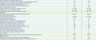
Below we present the key technical characteristics of the machine to which this article is devoted:
- weight – 450 kg;
- desktop: movement per turn of the handle – 2.4 mm, width – 320 mm, length – 360 mm, vertical movement possibilities – no more than 350 mm, T-shaped slots (total number) – 3;
- the maximum distance to the table from the spindle (the distance is measured from its end) is 650 mm, the minimum is 0;
- machine reach – 200 mm (the indicator implies the distance from the rack guides to the axis of the spindle, which is in a vertical position);
- spindle: sleeve stroke – 150 mm, movement of its head – no more than 300 mm, number of speeds – 9, a revolution of the handwheel moves the spindle head by 4.4 mm, and a revolution of the handwheel-handle moves the spindle itself by 110 mm, rotation speed – from 177 up to 1840 rpm;
- electric motor: power - 1.5 kW, number of revolutions per minute of operation - 1420, type - AOL2-22-4S2, coolant is supplied by electric pump PA-22;
- mechanical indicators: feed force - up to 560 kgf, minimum feed (vertical) of one spindle revolution - 0.1 mm, maximum - 0.56, steps - 6;
- unit width – 590 mm, length – 870 mm, height – 2080 mm.
The single-spindle drilling unit is a box-shaped column mounted on a foundation slab. The spindle head is located in its upper part. The head has a spindle with a high-speed steel tool and an electric motor.
The spindle head is mounted on the (vertical) guides. The feed mechanism, which ensures the vertical movement of the spindle, is located inside this unit.
The spindle is raised and lowered manually (using a steering wheel) and mechanically. The parts to be drilled are mounted on the machine table, which also serves to secure the workpieces.
Based on their parameters, you can adjust the height of the table.
The kinematic principle of operation of the unit is as follows:
- the gearbox allows you to control the spindle by changing its speed;
- the electric motor is designed to rotate the shaft, from which the movement is supplied to the kinematic chains of the unit (there are two of them);
- in the gearbox there is a hollow sleeve with a splined hole (this unit is called the final shaft), it is this shaft that rotates the spindle;
- if the engine is reversed by the operator, the spindle is also reversed (the need for such an operation arises when thread cutting is carried out on the machine).
The spindle carries out its work program using a rack and pinion drive. The quill rack engages with the rack wheel, and when it rotates, the spindle moves along with the quill (vertically). Through the spur gears, the drilling machine can perform six different gears.
The feed device and spindle, as well as the feed and speed box are located in the drilling head. The latter, through a rack and worm pair, moves along the machine column (this movement is set by one of the control handles). In the vertical direction, the table moves manually (in this case, the movement occurs through a screw and conical pair).
The control elements of the installation include the following elements:
- handles for lifting and clamping the table, clamping the drill head, switching speeds and feeds, controlling the feed mechanism;
- cams necessary to control work cycles;
- switches for mechanical feed, cooling pump, lighting;
- adjusting bolts (with their help, the table or drill head is jammed in the desired position);
- push-button station (“Left-Right-Stop”);
- automatic input switch.
The equipment is connected to the electrical network through a 3/4-inch hole.
The machine has the following electrical equipment:
- selenium rectifier;
- a motor that sets the spindle rotation;
- local lighting;
- cooling pump;
- automatic and starting mechanism.
The unit is controlled using an input machine, three buttons for moving right, left and stopping the machine. Also in its design there is a special starter that controls the cooling pump (starting the device and stopping it).
Equipment grounding is mandatory. It is carried out in accordance with the standards common to production devices. The machine motor is protected from short circuits and excessive loads by an automatic switch, AST-3 series. And the starter coil provides zero protection for the installation.
The principle of operation of the electrical circuit of the drilling unit: when the starter is turned on (the “Right” button on the control panel), the block contacts block it, after which the intermediate relay begins to operate, supplying power to the spindle.
In cases where reverse is intended, the intermediate relay turns on the second starter (the “Left” button), designed specifically for this mode of operation of the machine.
When you press “Stop,” the first or second starter (depending on which one was activated) and the intermediate relay are turned off.
Dynamic braking of the spindle, implemented on the machine, is performed according to a scheme that involves the use of a selenium rectifier, which initiates the operation of the brake starter. In this case, the supply of current (DC) occurs with simultaneous short-circuiting of the stator winding, which guarantees a more efficient braking process.
Source: https://tutmet.ru/stanok-2n118.html
Technical characteristics of the vertical drilling machine 2N118
The 2N118 vertical drilling machine is not intended for use in enterprises with medium and large-scale production. The manufacturer recommends this equipment for equipping experimental and mechanical repair shops where products are manufactured in small and single batches.
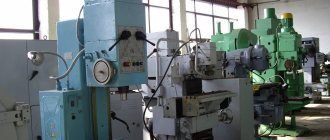
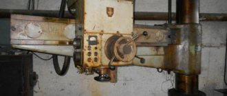
Appearance of vertical drilling machine 2N118
Brief information about machine grading
Classification of units:
- Machining of small holes up to 16.0 mm. Most often, such diameters are used in instrument making.
- Processing of medium and large diameters from 18.0 to 75.0 mm.
- Radial drill type for drilling large products.
- Machines for drilling high-precision diameters.
- Milling type.
- Centering machines.
- Multi-spindle machines.
Multi-spindle machine
Features of the machine model 2N118
The 2N118 machine, due to its technical characteristics, allows you to perform such technological operations as:
- drilling and reaming holes;
- deployment;
- countersinking;
- internal thread cutting;
- trimming the ends of parts (using a special tool).
Using a vertical drilling machine of this model, holes are formed in the metal, the diameter of which reaches 18 mm. At the same time, a torque of up to 880 Nm is developed, and the maximum value of the working feed is 560 kgf.
When performing processing on this machine, you can select different parameters for feeds and rotation speeds of the spindle assembly, which allows you to use such equipment most efficiently and with maximum productivity.
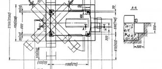
Dimensions of the working space and mounting bases of the machine
The first vertical drilling machine, model 2N118, was produced back in the 60s of the last century. The production of this unit was carried out by the Molodechno Machine Tool Plant, which to this day is an enterprise that produces efficient and reliable metal-cutting equipment.
Later, the Gomel and Molodechno machine-tool plants produced an analogue of the 2N118 – 2T118 vertical drilling machine. In addition to this model, specialists from the Molodechno Machine Tool Plant developed a number of modifications of the 2N118 machine:
- 2N118K – vertical drilling machine of coordinate type;
- 2A118 – drilling machine with a vertical layout, equipped with a single-spindle working head;
- 2N118F2 – machine with a software control system.
Vertical drilling machine 2N118-1 manufactured in 1987
Among the technical characteristics of the vertical drilling machine of the model in question (all of them are described in the equipment passport), it is necessary to highlight the following.
- The dimensions of the desktop, on the surface of which there are three T-shaped grooves, are 320x360 mm.
- The amount of movement of the work table per revolution of the flywheel handle is 2.4 mm.
- The maximum movement of the work table along the vertical axis is 350 mm.
- The weight of the device is 450 kg.
- The maximum distance from the end of the spindle assembly to the surface of the work table is 650 mm.
- The distance from the column guides to the axis of the spindle unit (machine overhang) is 200 mm.
- The spindle head can move up to 300 mm.
- The stroke of the spindle assembly sleeve is 150 mm.
- For one revolution of the flywheel, the spindle head moves 4.4 mm.
- The rotation speed of the spindle assembly is in the range of 180–2800 rpm.
- The rotation speed of the spindle assembly can be adjusted in 9 steps.
- The spindle assembly is made with a Morse taper 2.
- The shaft of the main motion electric motor (type AOL2-22-4S2), whose power is 1.5 kW, can rotate at a maximum speed of 1420 rpm.
- The PA-22 electric pump is responsible for supplying coolant.
- The maximum feed force for which the design of the 2N118 vertical drilling machine is designed is 560 kgf.
- Vertical working feeds per revolution of the spindle assembly are in the range of 0.1–0.56 mm.
- The machine's working feed parameters can be adjusted in 6 steps.
- Dimensions of the vertical drilling machine (DSV) – 870x590x2080 mm.
Machine characteristics in table format
Archive for machines
The universal horizontal boring machine 2A614-1 is designed for processing body parts with precise holes. interconnected by exact interaxal distances.
The largest mass of processed parts is 2000 kg.
The 2A614-1 machine, unlike the 2A615-1 machine, is equipped with a built-in faceplate with a radial support.
The machines have great versatility. They can be used for drilling, boring, countersinking and reaming holes, milling planes and grooves, as well as turning ends, boring holes and processing annular grooves with a radial support of the faceplate.
- The 2A614-1 machine, upon customer request, can be manufactured with a thread-cutting device.
- The presence of a mechanized tool clamp, rigidity, vibration resistance, speed and ease of control of the machine make it possible to carry out precise productive processing on them with the least amount of machine and auxiliary time.
- The machines are designed for use in tool and machine shops.
Technical characteristics of horizontal boring machine 2A614-1
Technical characteristics of machines are the main indicator of the suitability of a machine for performing certain jobs on machines. For horizontal boring machines, the main characteristics are:
- Table work surface size
- Retractable spindle diameter
- Maximum longitudinal movement of the spindle
- Spindle revolutions per minute
Below is a table with the technical characteristics of the 2A614-1 jig boring machine. More detailed technical characteristics of the machine can be found in the passport of the machine 2A614-1 located below.
| Name of parameters | Unit. | Quantities |
| Machine accuracy class according to GOST 8-77 | N | |
| Retractable spindle diameter | mm | 80 |
| The end of the retractable spindle with a cone for holding the tool | 40AT5, Morse 5 | |
| Built-in turntable dimensions (L x W) | mm | 1000×1000 |
| Vertical movement of spindle head | mm | 800 |
| Longitudinal movement of the retractable spindle | mm | 500 |
| Longitudinal movement of the built-in rotary table | mm | 1000 |
| Lateral movement of the built-in rotary table | mm | 1000 |
| Radial movement of the built-in faceplate support | mm | 125 |
| Retractable spindle speed | rpm | 20…1600 |
| Faceplate rotation speed | rpm | 6,3…200 |
| Feed limits of working bodies | mm/rev | 0,02…8 |
| Feed limits of the retractable spindle, spindle head, table in both directions. | mm/min | 1,26…2000 |
| Feed limits of the built-in faceplate caliper | mm/min | 0,5…800 |
| Speed of fast installation movements of the retractable spindle, headstock, table | mm/min | 5000 |
| Speed of fast installation movements of the built-in faceplate caliper | mm/min | 2000 |
| Maximum permissible torque on the retractable spindle | Nm | 865 |
| Maximum permissible torque on a triple faceplate | Nm | 1300 |
| Maximum permissible spindle feed force | kN | 7,5 |
| Maximum permissible table feed force | kN | 10 |
| The largest mass of the processed product | kg | 2000 |
| Overall dimensions of machines without attachments (LxWxH) | mm | 4518x2590x2585 |
| Weight of machines without electrical equipment and accessories | kg | 8500 |
Kinematic diagram and equipment design
The supporting element of a vertical drilling machine of this model, equipped with a single-spindle head, is a massive box-shaped column mounted on a base plate. The headstock of the device is mounted in the upper part of the column, which can move along its guides. On the headstock there is the main electric motor of a vertical drilling machine, and on its lower part there is a spindle assembly with a working head in which the cutting tool is fixed.
Machine spindle head - front view
In the inner part of the spindle head there is a gearbox, which is responsible for adjusting the rotation speed of the drilling head, as well as ensuring the movement of the latter in the vertical direction. A rack and pinion mechanism, present in the kinematic diagram of the headstock, is responsible for raising and lowering the working head of the machine, and the body by which this mechanism is activated is a special steering wheel.
Before processing, the part is fixed on the surface of the work table, which also has the ability to move along the column guides. The height of its location, which is chosen depending on the dimensions of the workpiece, is changed using a rotating handle located on the front side of the unit.
Height-adjustable machine work table
The elements included in the kinematic diagram of the vertical drilling machine under consideration function as follows.
- The gearbox, due to the presence of several shafts and a number of gears in its design, allows you to adjust the speed of rotation of the drilling head in 9 steps. The output shaft of the gearbox, which is connected to the spindle assembly of the machine using a spline connection, is made in the form of a hollow sleeve. By reversing the drive motor, you can change the direction of rotation of the working head of the equipment, which is necessary if an internal thread is being cut in the workpiece.
- The spindle feed in the vertical direction, as mentioned above, is carried out by a rack mounted in the equipment quill and a gear engaged with it installed in the spindle head. The machine’s feed box, which contains several gears, allows you to adjust the vertical movement of the spindle assembly in 6 steps.
- Both the gearbox and the feedbox are installed in the spindle head of the vertical drilling machine, which can also move vertically along the column guides. A corresponding handle is responsible for this movement, carried out through a rack and worm connection.
- Vertical movement of the worktable, triggered by rotation of the corresponding handle, is provided by a conical and screw pair, which are equipped with the kinematic diagram of this structural element of the machine.
Kinematic diagram of a vertical drilling machine 2N118
The elements by which the operation of a vertical drilling machine of this model is controlled include:
- automatic type input switch;
- work area lighting switch;
- a switch for starting and stopping the coolant pump;
- handle responsible for controlling the feed mechanism;
- a button that turns on the feed mechanism;
- handle for selecting feed parameters;
- a push-button station on which the “Left”, “Right”, “Stop” buttons are mounted;
- a handle responsible for selecting the required rotation speed of the drilling head;
- a handle that provides clamping of the drill head;
- bolts with which the wedge of the drilling head is adjusted;
- bolts for adjusting the wedge of the work table;
- a handle used to clamp the desktop;
- a handle responsible for lifting the desktop along the column guides;
- a square end of the roller, through which the mechanism for lifting the drilling head is activated;
- cams, with the help of which the equipment operating cycles are configured;
- hole (3/4 inch) in which electrical contacts are located for connecting equipment to the power supply.
Equipment controls
There are a number of elements of the unit:
- Automatic power switch.
- Toggle switch for work surface lighting.
- Cooling system fluid pump switch.
- Handle for adjusting feeds.
- Button to activate feed.
- Regulator for selecting feed speeds.
- Control unit and direction of spindle movement.
- Drilling head rotation speed regulator.
- Bolts – clamps of the wedge of the working head.
- Handle for fixing the work table clamp.
- Electrical contacts and network power board.
- To provide auxiliary control, a number of buttons, an automatic starter, and a manual starter are used.
Elements of the electrical circuit of the device
The electrical circuit of the vertical drilling machine of the model in question includes the following elements:
- an electric motor that rotates the drill head;
- an electric pump responsible for supplying coolant to the processing zone;
- starting equipment and automation elements;
- selenium type electric rectifier;
- a step-down transformer from which the selenium rectifier is powered;
- elements included in the local lighting system.
Schematic diagram of the machine
The vertical drilling machine of this model uses a dynamic braking system, which functions as follows: a direct current generated by a selenium rectifier is supplied through the contacts of the brake starter to the three phases of the stator winding of the main electric motor. To ensure effective braking of the electric motor shaft when DC current is supplied to its stator, one of its windings is short-circuited in two phases. The braking of the electric motor shaft occurs at the moment when the corresponding button is pressed on the machine panel.
The electrical circuit of a vertical drilling machine works according to the following principle. When you press the “Right” button on the control panel (main operating mode), the first starter is started, which self-blocks with some of its contacts, and through others supplies power to the intermediate relay. The electric current through the intermediate relay, which is self-powered, can also be supplied to the second starter, which starts the rotation of the motor shaft in the opposite direction.
The electrical panel of the machine contains protection and automation elements, as well as an electrical circuit for dynamic spindle braking
The second starter, some of whose contacts are also self-locking, is turned on after pressing the “Left” button on the equipment control panel. Regardless of which direction the electric motor shaft rotates, when you press the “Stop” button, the corresponding starter is disconnected from the power supply and the braking starter, which is responsible for supplying direct current to the stator winding of the electric motor, is started.
The characteristics of this vertical drilling machine include the presence in its circuit of an automatic switch that protects the electric motor from overloads and short circuits. The machine also provides zero protection, which is possible thanks to the use of a magnetic starter coil in its circuit.
To ensure trouble-free operation and operator safety, it is necessary to ensure high-quality grounding of the vertical drilling machine, which must be carried out in accordance with all generally accepted requirements relating to production equipment.
Table of contents
The 2N118 vertical drilling machine is designed to perform drilling work with a maximum drilling diameter of 18 mm. In addition, it is possible to perform other work: drilling, countersinking, reaming and threading.
The device of a vertical drilling machine
- Column, table, stove;
- Gearbox;
- Gearbox;
- Drill head;
- Machine spindle;
- Cooling system;
- Electrical equipment
Controls of a vertical drilling machine
- Local lighting
- Coolant pump
- Circuit breaker
- Feed mechanism control handle
- Turning on mechanical feed
- Feed switching
- Push button station
- Switching speeds
- Drill head clamp
- Drill head wedge adjustment bolts
- Table clamp
- Table wedge adjustment bolts
- Lifting the table
- Drill head lifting mechanism roller square
- Cycle adjustment cams
- Connecting the machine to the electrical network
Kinematic diagram of the vertical drilling machine 2N118
Electrical diagram of a vertical drilling machine
Vertical drilling machine gearbox
The gearbox of a vertical drilling machine, using two triple gear blocks 1 and 2, transmits nine different speeds to the spindle.
The gearbox mechanism consists of an electric motor located vertically and a gear transmission 5. Due to this transmission, it is possible to change the gear ratio, thereby changing the spindle speed range.
The output shaft of the gearbox 8 is made in the form of a sleeve with a splined hole that transmits torque to the machine spindle.
Speed switching is carried out using handle 10, which has three circumferential positions and three axial positions. The handle, through gears 11, 12 and rack 13, moves rods 14 and 15, which are connected to forks 16 and 17. The forks, in turn, switch movable blocks 1 and 2.
Feed box of vertical drilling machine
The feed box of a vertical drilling machine consists of three shafts mounted in a separate cast housing 1.
The feed box provides six feeds using a movable triple block 2 and a double block 3. The rotation of the feed box is transmitted from the gear wheel sitting on the spindle sleeve to gear 4.
The third shaft 5 transmits torque through a gear transmission to the ball clutch and the worm of the feed mechanism. The ball clutch is designed to turn off the feed when the required drilling depth is reached. It also serves as a safety device in case of overload in the feed force.
Speed switching is carried out using handle 13, which has two axial positions and three circular ones. The design of the feed and speed switching mechanisms is identical.
Lubrication of both the feed box and other mechanisms is carried out from gear pump 12.
Drill head of vertical drilling machine
The drilling head of a vertical drilling machine is a cast iron body into which the following machine components are installed:
- Machine speed box;
- Machine feed box;
- Headstock;
- Feed mechanism
The main part of the drilling head assembly is the feed mechanism, consisting of a worm gear 1, a horizontal shaft with a rack and pinion gear, a dial 3, a steering wheel 4, a cam clutch 5 and a ratchet clutch 6.
Characteristic advantages of the machine
Drilling machine 2n118 is designed for drilling small holes up to 18.0 mm in metal surfaces. In order to improve the quality of work, a maximum torque of 880 Nm is developed and the feed is equal to 560 kgf. When working with each part, it is possible to select the speed and feed amount, which makes the work more accurate and efficient, and reduces the risk of defects.
Similar models:
- 2A118 layout and single-spindle head.
- 2N118F2 modernized version with an automated control system.
- 2b118 with an increased number of feeding stages.
- Vertical mechanism 2N118K.
Machine 2N118K
