Elements in the form of curls, made of rods, are widely used in the design of local areas and the interior of residential premises. Special devices are used for their manufacture. One of them is a snail. Home craftsmen often construct this device themselves from scrap materials. If you also want to know how a snail is made for cold forging with your own hands, then this article is for you. From it you will learn the operating principle of this device, its advantages and varieties, simple drawings and self-assembly technology.
Cold forging method
The method involves using an important property of metal - plasticity.
With the help of various mandrels and mechanical devices, the rod is bent in different directions, twisted, and forms various three-dimensional shapes. As additional processing, welding and metalworking operations are used to connect parts of workpieces. Entry-level machines are quite simple and are driven by the muscular strength of the master working on them. The minimum set of forging equipment for cold forging of metal includes:
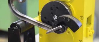
- Bending machines, or Gnutiki, are used to bend workpieces at a given angle and radius.
- Twisters, or torsion bars, are used to twist a workpiece (or group of workpieces) around the longitudinal axis
- Wave - used to create periodic bends in different directions.
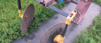
- Snail forging machine - used to create spiral-shaped curls at the end of a rod.
Is it possible to master cold forging yourself? Yes, it is enough to have basic skills in metalwork, design and machining.
Many home craftsmen have made a snail - a cold forging machine on their own, without using expensive components.
Pros and features of the process
Cold forging is a popular type of work due to the fact that it can be used to create unusual parts of various shapes and sizes.
Using a cold forging machine, you can make a fence for a flower bed, a decorative lantern, an unusual fence, railings or handles for a bench and other elements.
Another advantage of cold forging is that it is quite easy to make a machine with which you can create such parts with your own hands. This will help you save on the purchase of expensive equipment.
The cold forging process consists of three main elements: bending, pressing and welding of parts. The equipment needed for this process is quite simple and compact, you can do it yourself and it will not take up much space in your workshop or garage.
You can start learning metal processing with cold forging, because... this process is easier and safer because you don't have to deal with high temperatures like other types of welding.
For this process, a ready-made template is usually used - that is, blank parts.
Of course, cold forging has its own subtleties, they mainly consist in the fact that the part is easily damaged or deformed during the process: forged elements often break, and the defect cannot be corrected, so forging must be done very carefully.
However, using a high-quality machine and a drawing of the future part, you can easily learn how to create products with twisted, wavy and other unusual shapes. You can see the options in the photo above.
The process of processing blanks through cold forging occurs in several stages. The first step is to create a template or drawing of the future design.
It is necessary to calculate the dimensions of the product in order, firstly, to purchase the required amount of material, and, secondly, to properly configure the machine.
Different machines provide different possibilities for creating patterns - this depends on the complexity of making the tool.
For example, the simplest do-it-yourself machines can only bend products, while with the help of more complex models you can create patterns, etc.
After the template or drawing is ready, you need to buy the required amount of material in accordance with your calculations. For cold forging you will need iron rods, you can buy them in the store.
Rods for cold forging should not be too thick, otherwise they will be difficult to bend. The next stage is making the parts yourself:
The most important thing here is to set the settings correctly so that during operation of the machine the parts are not damaged or deformed, because it will be impossible to fix the problem.
Lastly, the completed parts are secured to the frame. This happens by welding.
You need to be especially careful when welding with your own hands with thin-walled tubes, because... It’s easy to burn through them, and then the design will become faulty and you’ll have to do it all over again.
You can watch the entire forging process in the video before you start working on your parts.
But before you start cold forging, you, of course, need to make the machine that is necessary for this. The “Snail” machine is the most common apparatus for processing metal products using the cold forging method with your own hands.
You can see all the stages of creating the machine in the video - there is nothing complicated about it, and almost everyone will be able to cope with this task themselves.
Bends, flashlights, waves and other machines
As you can see, we have collected all other types of cold forging machines in one small section. Why is there such disrespect for them, in contrast to the snail and torsion bar, which we talked about in separate sections? The answer will be honest in the form of advice:
If you decide to make a forging machine with your own hands, opt for two machines: a snail and a torsion bar. Firstly, they are absolutely necessary from a functional point of view, and secondly, they are quite simple to implement independently.
Types of cold forging.
The remaining machines, such as a flashlight or a wave, can be built much later, when you realize that cold forging is for you, and when you have specific creative plans in your head.
There is no need to make a bending machine yourself; it is better to buy it ready-made for two important reasons:
- Wedges and rollers, which are used to change the dimensions of manufactured elements, must be machined to the ideal dimensions. It is almost impossible to do this at home.
- Bending machines are very inexpensive, so the budget saving requirement will be met.
Having at your disposal the three most necessary machines - a self-made volute and torsion bar and a purchased bending machine - you can begin cold forging of almost any complexity. There is one more small issue left to resolve.
What is produced using the cold forging technique
That is, where we can direct the result of our work. And, as practice shows, there are not so few options. Especially if you live in a private house or have your own dacha.
- All kinds of furniture for your garden. From small and cozy benches to large fences on terraces, consisting of branched forged ornaments. Various barbecues, chairs and more.
- Fencing of all types. Moreover, both for the external type, along the perimeter of the territory, and for the internal purely visual gradation.
- Coverings for gazebos.
- Sports equipment of different types.
- Frame buildings for growing crops.
As you can see, if you have a drawing to make a cold forging machine with your own hands, then it is possible to subsequently acquire a huge number of extremely useful things for the garden and home. As they say, there would be a desire.
Twister device
“Twister” is a tool for twisting rods, mostly square, along the longitudinal axis. This simple device can be manual or electric. Operating principle: both ends of the rod are secured, then one fastening begins to rotate, twisting the metal to the required shape.
Appearance of a purchased manual “Twister”
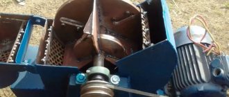
Look at the photo of a homemade “Twister” with an electric drive, assembled using used electrical equipment:
There is a special machine for making “Lanterns” and “Cones”, but for starters you can also use a “Twister”, as shown in the video (English, but everything is very clear).
Read also: Three-phase electrical wiring diagram in a private house
Video: how to make a blank for “Flashlight” on “Twister”
Devices for bending metal elements “Snail”
To bend workpieces according to certain parameters, auxiliary conductors are used, called “Snail”. They serve as a special template that allows you to reproduce dozens and, if necessary, hundreds of similar parts. The “Snail” machine for cold forging bends parts without additional heating.
The work is based on the deformation of metal according to a certain principle. To bend, you have to put in a lot of effort. Therefore, craftsmen quite often equip “Snail” devices with an electric drive. Geared motors help to develop significant forces with a limited shoulder of force application. The torque in the processing area can reach several tens of kilograms.
If such work is performed only due to the physical strength of the blacksmith, the worker will get tired quite quickly. Its productivity will drop to zero. And with a mechanical assistant, hundreds of workpieces can be produced per shift.
It must be taken into account that bending of workpieces is an intermediate stage in the manufacture of complex structures. They still need to be installed in the right place and welded. Only then will an intermediate result be obtained. Then the product will need to be painted and installed at the place of order. All operations will require not only time, but also the physical strength of the master.
Structurally, the device can be:
- Non-separable, then it will be used to bend parts only to certain lengths. The resulting spiral has certain limitations in use.
- Prefabricated (there are additional fragments to increase the bending time), and the device can be used to bend long parts. Large sized parts will be received.
To work with parts from small profile pipes, some make manual devices. They involve the use of levers to help move the workpiece around the mandrel. The finished parts are removed from the end, slightly loosening the tension.
Most often in such cases I use square bars □8...12. Some craftsmen manually bend profile pipes 15·15 mm with a wall of 1.5 mm. For larger products, a mechanical drive is required.
Required Tools
To assemble a pipe bender, you need at least the following tools:
- welding inverter;
- angle grinder;
- lathe (or purchase of finished parts);
- vice;
- hammer;
- metal file;
- sandpaper;
- ruler;
- drill.
But the most important thing is the pipe bender drawings. The mechanism must be manufactured strictly according to the drawing. You can take a ready-made drawing from this material or find another one and adapt it to the required dimensions.
But it is impossible to make a pipe bender without a drawing, since precise calculations are needed to ensure the operation of the mechanical parts.
Features of the snail
The author specifically decided to draw the reader's attention to a number of points. This will help you avoid some mistakes in the future. For example, having understood the structure of the snail and the principle of its functioning, someone will want to assemble their own device, different from those whose drawings will be presented below.
Such a device (if we are talking about equipment made by hand) will allow bending samples using the cold forging method with a cross-section (square side) of no more than 10 - 12 mm. This implies a “manually controlled” snail model. Almost no one has anything to do with larger samples in everyday life. The machine can be improved by installing a drive and an electric motor.
But how rational is this for a small home forge?
- Cold forging is carried out at low speeds. A sharp change in the geometry of the metal leads to the appearance of cracks (ruptures).
- You will have to not only select the power of the electric motor, but also the gear ratio of the gearbox. Plus, you need to mount the automation circuit with the installation of the corresponding elements (buttons, starter, and so on). All this significantly complicates the manufacture of the machine.
How to do what you need
To make a cold forging machine with your own hands in the most effective way, you need to start by developing a drawing. It is used to calculate the need for materials and the possibility of replacing them with those available. The technological operations diagram will allow you to determine the necessary tools and equipment for manufacturing the machine.
Homemade sketch drawing of a gnitik machine
How it works and what it is like
At its core, it is the deformation of metal rods in the form of their bending. In order for the rod to deform without heating, it must be rigidly fixed to the machine template. This machine is not for weak hands: scrolling and deformation are done using manual effort.
Of course, the snail can be equipped with an electric motor drive. But before that, you need to carefully consider the feasibility of this drive. The main argument for an electrical addition is the large amount of work involved.
Snail for forging - drawing. The machine can operate in two different designs:
- The simplest option is a template welded to the base. This is a monolithic conductor with a single curl option in the form of a template.
- An option that gives more variety in curls is several modules with curls of different diameters, which are attached to one base.
Manual drive can also be provided in different options:
- The lever can be any suitable device.
- A lever that is attached to a frame and driven by a moving bearing.
- More complex designs use as many as three levers that rotate the axis and the conductor attached to it.
How to make a snail for cold forging, which option to choose - easier or more difficult? The choice again depends on expediency, in other words, on your production plans: what are you going to do, with what productivity and in what quantity?
What kind of devices are used?
Cold forging is characterized by various curls, bends, twisted rods, etc. Almost every type is made on a separate device - a specific machine. They can be driven manually or electrically. For small volumes “for yourself”, manual cold forging machines are used. Although they are not particularly productive, they are much easier to manufacture. If it is necessary to put production on stream, similar devices are made, but with electric motors. In this case, there is almost no need to physically work, but the complexity of making the device increases significantly. In our material we will talk about manual machines for cold forging.
What devices are used:
- Torsion bars. With their help, tetrahedral rods or strips of metal are twisted in the longitudinal direction. The result is twisted columns, which are also called torsion bars.
This is what a torsion bar and the machine of the same name look like
This is how they make a flashlight
Device for cold forging snail - for forming curls
For bending anywhere and at any angle - bending machines (bending machines)
Machine "Volna" - for the formation of the appropriate relief
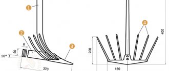
Machines for shaping the ends of rods. In this case - crow's foot
For a beginning craftsman, the most relevant machine for cold forging is a snail. Only with its help you can make many interesting things - from a fence and gate to a bench and other similar products. In second place in terms of necessity is a torsion bar machine. It adds variety to the details. All the rest can be purchased or made as you improve and gain skill.
Design specifications
The dimensions of the volute for cold deformation are determined by the diameter of the rolled product being bent and the required curl size. A sketch of the design of the forged product is first made. It is broken down into individual elements. For each spiral, a conductor is made - a snail or any other.
The simplest machines for cold forging have a massive, durable stand, at the upper end of which there is a groove for fixing a plate with a jig. Deformation is carried out due to the efforts of the master’s hands. He clamps the end of the rod and walks around the fixture.
If there is a rotary table and a lever, it is possible to produce volutes for rolling of a larger cross-section.
Flashlight device
This machine produces blanks for “Lanterns” or “Pine Cones” elements, which can consist of 4, 6, 8 or more rods. According to the principle of operation, the machine is similar to the “Twister”, but here the workpieces are bent around the guide shaft, which forms a more correct and accurate configuration of the product.
Flashlight device
Operation of the device for making “Flashlight”
Types, structure and principle of operation of the cochlea
Several varieties of the popular machine are used. All of them, regardless of the details of the cochlea device, use a general operating principle. A strip or rod of metal is forcefully pressed against a stationary template or against a movable ploughshare of the snail, forcing it to take the shape specified in the drawing.
- monolithic non-separable volute using a fixed metal template. Used to produce series of identical products
- removable design - bending is carried out around pins inserted into holes on a solid plate. Suitable for the production of unique parts with complex configurations, the cross-section of the rod is limited.
- Collapsible volutes with rotation are more complex in design, but make it possible to obtain identical products of complex shape with great accuracy
Crossbow type pipe benders
These pipe benders got their name because of their resemblance to a crossbow. The basis of the design of such a device is a frame made by welding from corners and channels. Inside such a frame, on which two movable rollers are mounted, there is a jack, which, using a special shoe, creates a force directed at the pipe. Pipe benders with movable rollers and a pressure shoe are used primarily for bending round pipes, since they can simply deform any other type of product.
A rugged, no-frills crossbow pipe bender
Buy or make
It is better to pose the question in a different way. Do you need a large, high-quality batch of reference parts or just need to bend a couple of pipes? It’s still impossible to create a machine with minimal deviations using artisanal methods. And in terms of service life it will lose to the factory one. But for performing periodic (this is the key point) work, a homemade option is quite suitable. If the final parts do not require the highest dimensional accuracy. Otherwise, all that remains is to buy the necessary equipment.
Devices for making crow's feet
“Crow's foot” - flattening with the application of beautiful notches at the ends of the workpieces to make the structure more elegant or to reduce the thickness for various joints.
The ends of the elements are decorated with “houndstooth”
This operation can be performed using a machine with a die or fixture and a heavy forging hammer on an anvil. We provide both options in the form of videos.
Machine for making houndstooth
Tools for forging crow's feet
Detailed stamp making process
Below is a rolling machine to perform the same operation.
Machine for rolling "crow's feet" (the distance between the rollers is adjustable). Materials for a rolling machine: gears and shafts - spare parts from a used combine
Operating principle
Manufacturing technology of the “Snail” device
In a simplified way, the technological process of making a “Snail” machine with your own hands can be represented as a series of sequential operations.
- A profile of the product to be manufactured is drawn on a sheet of paper. When drawing, the dimensions of the product are maintained. The drawing is needed only to obtain the profile of the part itself. Attention! When processing, the thickness of the workpiece is taken into account. A gap of at least 3...4 mm is needed, then the product can be removed after bending it in the device.
- For most machines, a central stop is made. It will record the beginning.
- Different craftsmen use their own fixation techniques, so their products can be distinguished by their handwriting.
- A support plate is cut from a steel sheet. The center will be welded to it, as well as the spiral. The thickness of the plate must be at least 3 mm, as significant forces will be applied. The size of the plate in the future will also determine the parameters of the curl.
- Using the spiral drawing, the workpiece is bent from the strip. When bending it, the parameters are controlled. The more accurately this element is manufactured, the easier it will be to manufacture elements for forging products. Attention! If it is necessary to make curls with more than one turn, you need to cut the spiral strip diagonally. Therefore, a strip of much wider width is used. The minimum size corresponds to the height of the profile that is going to be bent on the machine.
- The device is placed on a special rack to make it easier to form finished products. For small parts it is convenient to place them on a vertical stand.
- To make the job easier, weld the handle. It is installed on the reverse side so that it does not interfere with the installation and removal of workpieces.
Tricks of the Masters
The use of spacers allows for an instant change in the shape of the final structure or making bends in the opposite direction, which the plowshare does not allow for structural reasons.
Does not require increased precision in the manufacture of parts.
Fastening the workpiece is as easy as shelling pears – place it in a special recess.
Allows the use of a technique that is used in industry - a slight bend in the opposite direction in the core of the curl.
It is possible to use different techniques and bends in forging
Such cold forged products look better and are more expensive.
Additionally, it has a good and convenient advantage - the ability to produce flat bends with a thin core from a workpiece lying flat.
The lever machine allows the installation of a clamping roller at a height of strip thickness and a flange wider than a railway wheel. This method requires painstakingness: the lever must be moved little by little, otherwise the inner edge will be damaged. Unfortunately, this is the only method for making such curls in DIY production.
A machine with a lever is often created without the use of rare or expensive materials and without having accurate diagrams.
Making a simple snail with your own hands
The snail machine usually has replaceable jigs of different sizes. First, a tool template for cold forging is drawn. Then a snail is made from it - a conductor, or rather an open stamp for winding. A snail of the desired shape is cut out and attached to the base.
The most aesthetically pleasing are spirals made according to the golden ratio principle. To do this, you need to draw a square with a side equal to the cross-sectional size of the rod for which the jig is being prepared. Then the compass is placed alternately at each vertex of the square and a line is drawn clockwise. The line should end near the beam on which the compass leg stands.
Drawings of a snail for forging
Novice craftsmen often neglect the importance of the design stage and make templates for cold forging by eye. This may be enough to “feel the metal” and understand the essence of the process with your own hands.
Drawing of a snail for forging
But if you want to get beautiful products as a result, and even more so if you are planning to produce a series of identical elements, then when manufacturing a machine you cannot do without accurate calculations of all parameters - bend angles and radii, torques, maximum forces and others. An accurate calculation will allow you to create with your own hands a high-quality snail machine for cold forging, which will last a long time and will delight you with ease of operation and high-quality aesthetic products.
Dimensions of the future machine
Before you start making a homemade jig for making decorative curls, you must first decide on the dimensions of the main parts.
In particular, we are interested in the dimensions of the central part and the curl. Based on the actual dimensions of the template, the dimensions of other structural elements are determined - for example, the frame on which the bending jig will be attached.
To create a snail machine for cold forging with your own hands, drawings and dimensions, if necessary, can be selected on thematic sites (or look for suitable options on forums on this topic).
Moreover, there are many different options for homemade designs. Let's look at one of them.
To make the drawing we will need:
- square steel bar 10x10 mm;
- A4 sheet of paper;
- square;
- pencil and compass.
First of all, we place a square rod in the middle of a sheet of paper and draw two parallel lines.
Then we apply the rod in a perpendicular plane at an angle of 90 degrees (we use a square for this), and draw two more lines.
As a result, in the center of the snail template we should get a square measuring 10x10 mm, from which four lines extend in different directions.
We take a compass, place it in the corner of the square, and draw a semicircle.
Then we move the compass to another corner (we go in order), and also draw a semicircle, continuing the previous line.
And we do this until we get a curl of the required size - the main part of the snail drawing.
After this, use a compass to draw a circle (in this case, the diameter of the circle is 43 mm).
The drawing is ready. Now you need to select a steel blank of a suitable diameter and cut off a piece about 30 cm long from it. The beginning of the curl (center) is cut out from this blank.
Draw a drawing yourself or download it from the Internet and print it on a printer - it’s up to you.
There is another way to make the central part - we will talk about it in detail below.
Making the central part of the conductor
Equipment and tools that will be required for work:
- drill press or drill;
- Bulgarian.
We cut out one large circle from sheet metal 18-20 mm thick (this will be the base plate) and four small circles to make the center of the jig.
The made center is attached to the frame using fastening bolts (the author uses hexagon bolts) - for this we drill coaxial holes in the workpieces.
Next, we draw out the profile that will need to be cut using a grinder. We process the workpiece with a petal circle.
At the next stage, we will look in detail at how to make a snail. You can use a square or strip as the starting material. If there is no strip, it can be cut from sheet metal of suitable thickness.
Making a conductor blank
We proceed to the next stage of work - we are engaged in the manufacture of a device for forging metal, along which the workpiece will be bent. Let's take a square rod as a basis.
On a bending machine we bend two curls of equal length. We fasten them together using masking tape and mark the locations of future holes using a center punch.
We drill holes and cut threads for the mounting bolts. The finished contour of the snail will be bolted to a metal support plate (frame).
When the main parts are ready, you can begin the final part of the work - assembling the cold forging machine with your own hands.
To do this, you will also need to make a bed, and think about what materials to make the base from and how it will be attached to the workbench or other supporting surface (for example, a horizontal platform located on a stand).
Final assembly of the machine
We make the machine bed. To do this, we need two pieces of metal corner and a metal plate that will be installed vertically.
The top edges of the plate will need to be rounded. We drill holes in the prepared parts, and then connect them together using bolts.
In the metal plate we drill a hole for the shaft, for which a steel round timber is used.
Additionally, it is necessary to drill mounting holes for attaching housing bearings. Next, screw the bearings onto both sides of the plate and install the shaft.
As you can see, there are no difficulties in making a snail for cold forging with your own hands.
Moreover, the variant of the conductor discussed above is collapsible, which is very convenient - this greatly simplifies the storage of the device when it is not in use.
We attach the central part to the base plate, then screw curls from a square rod onto the bolts.
We attach the shaft to the back side of the support plate. Then we install the assembled volute jig for cold forging on the vertical plate (bed) of the machine.
Additionally, we drill a hole in the plate and install a shaft with support bearings.
At the end of the main shaft we drill a hole into which we insert a handle made of a steel round bar. The step-by-step work process can be seen in the video below.
Making a guide for the conductor
For these purposes, you will need an ordinary lathe of type 1K62 or 16K20, which is capable of cutting an Archimedean spiral, and, of course, an experienced turner.
The “Archimedean spiral” function in lathes is intended for cutting special threads, but it is also quite suitable for obtaining a groove in the base plate, where the jig guide itself will then be located.
When preparing the machine, the following transitions are performed:
- The small handle of the machine feed box is moved to the “Archimedes Spiral” position.
- The required spiral pitch, which will determine the dimensions of the conductor, is set using a large handle.
- The feed step is fixed by a lever, and the feed amount is determined by the depth of the groove in the plate (how to set this parameter will be discussed later).
- After turning on the machine, the feed lever remains in the same position, and cutting is performed during the reciprocating movements of the spindle.
- After each pass, the support is moved away from the end of the workpiece.
An example of obtaining an Archimedean spiral is presented in this video:
The fact that the frames show not metal, but plastic, does not fundamentally change anything: the spiral is obtained as a result of several successive passes of the cutter, which moves along a given path.
The dimensions of the spiral groove are determined based on the desired dimensions of the conductor and the height of its supporting surface. If in the first case everything depends on the size of the initial workpiece for the plate and the capabilities of the machine, then the depth of the groove should be calculated based on the height and thickness of the guide matrix.
Since in a cold state any metal has increased mechanical strength, then to make a guide matrix with your own hands you should use tool steel: for example, grade U7 steel according to GOST 1435-84. It is not recommended to use high- or medium-carbon structural steel such as steel 45 or steel 60G, since for tall volutes they may crack under the influence of a bending moment.
The dimensions of the guide matrix in plan are selected based on the available range of strip tool steel in accordance with GOST 4405-75. Since the jig must be compact, it is advisable to choose profiles 3×20, 3×25 or 3×30 with a maximum thickness deviation of 0.4 mm. When fitting the guide into the plate according to H11, the width of the spiral groove should be 0.5-0.7 mm greater than the width of the strip. The groove depth must be at least 1.5 times the strip height, i.e. 4.5 mm or slightly more. This parameter, by the way, will determine the thickness of the slab itself: it should be at least 6 mm.
The total length of the guide is determined from the cut groove in the slab (you can use a flexible tape measure or even regular thread to measure). Then they cut the required length of the strip “to size”, insert it into the groove and scald it along the contour (if the jig will produce only flat snails, then along the outer generatrix, and if three-dimensional, then along the inner one).
A support hook is bolted to the center of the conductor. It must have a lead-in section with which the workpiece is fixed at the initial moment of spiral formation (see Fig. 3).
Making a simple part on a machine
The strip steel workpiece is cut to the required size. This size is usually clarified by drawing the finished product and its component elements.
The free end is placed in the center of the spiral. The workpiece is secured using an internal screw.
The “Snail” rotation is performed. The workpiece is pressed tightly against the guides. This requires some effort to obtain the desired product profile.
By turning the device further, a curl is made. If necessary, insert the other end of the workpiece and make a closed or open curl.
Usually the other end does not stay straight. It is also bent. Therefore, a distinction is made between internal and external reverse curls. Marks are made on the device itself using a marker or chalk. They are used as a guide when making curls with the required parameters.
As you can see from the step-by-step guide, using a simple set of tools, a homemade curl maker is easy to make. How much does it cost? Its price is determined by the cost of the blanks. Often the price is minimal.
Monolithic non-demountable snail
It is made like this:
- First, a diagram of the future template with the required dimensions is drawn on a sheet of paper (sometimes the template diagram is applied directly to the base of the conductor). This must be approached responsibly, because after welding the finished form, it will not be possible to correct errors. The thickness of the outline of the form in the drawing should be the same as the thickness of the metal strip used for its manufacture. It should be at least 3mm. The coils must be placed at a distance of 12–13 mm from each other, so that a 10 mm deformable rod fits into the groove between them.
- The base of the snail (preferably round) is cut out of a steel sheet with a thickness of at least 4 mm, the diameter of which is determined in proportion to the size of the template spiral and be larger than the size of the snail. Typically the diameter of the base is within 70 cm.
- In accordance with the drawing, the desired curl shape is made from a 3mm thick metal strip. To do this, it is better to calcinate the workpiece so that it is easier to machine. After making the mold, the excess end of the strip is cut off, and the edges of the snail are cut into a cone and cleaned.
- The finished form is welded to the base, which is mounted on the frame. Sometimes a template welded to the base is fixed to the frame using yews installed on it. To do this, a piece of timber is welded to the back side of the base of the form for gripping with a yew.
With the option of fixing the conductor in a yew clamp, you can easily change the templates and obtain different shapes of curls if you make several types, monolithically welded to the base of the devices.
Removable design
- On the working base, first draw the contour of the snail with a mark along the contour of the holes for attaching the template.
- Based on the sketch, a template is made from a thick steel strip and holes are drilled in it. It is attached to the base with bolts.
Forging a twisted shape should begin from the central curl. The end of the workpiece is inserted into the groove of the first curl of the form and pressed tightly against it. You can use a small clamping tool to secure the fixation. With force, the free part of the rod is screwed onto the template using a device - a lever. Advanced designs use a lever driven by a moving bearing mounted on it. The lever is made of a rod with a diameter of 20 mm.
You can watch the making of such a device in the video:
Collapsible snails with rotation
The snail template can consist of several parts, and the deformation of the rod occurs by rotating the conductor. This machine consists of the following elements:
- thick metal base in the form of a disk or square;
- a collapsible template fixed to the base area;
- rotation shaft;
- lever to drive the shaft.
The working base is made of metal, with a thickness of 4 to 10 mm.
The prefabricated template may consist of several parts that are connected to each other by hinge pins inserted into the holes of the lugs welded to the ends of the elements. Together they make up the outline of the cochlea.
To attach such a snail to the working base, you need to drill holes in it to fix it to the surface in a certain position. By changing the position of the prefabricated parts on the base, you can obtain different curvature of the curls and their shape. The size of the arc of the shape is regulated by special screws attached to the connecting hinges.
It is quite difficult to make a composite volute with hinged joints yourself. Typically, craftsmen purchase a stamp made in an industrial environment and attach it to the bed.
You can make a simpler collapsible template device yourself without using hinges. To do this, you need to make a sketch of the prefabricated parts of the snail with the locations of the holes. If you prepare several sketches and, in accordance with their contours, drill holes in the base in different places, then you can attach templates with different radii to one base. To do this, you will need to bolt the contour segments where the holes of the template and the base align.
For example, you can do this:
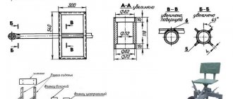
Drawings of a manual machine
Figure 3. Drawing of the base of the cochlea.
The machine, according to this drawing (Fig. 1), is mounted on a base, which is a rectangular slab with dimensions 220x190 cm.
This 5mm thick plate has two holes. One of them is round, with a diameter of 14 mm, for the shaft axis, and the second is oval, with a width from 6 mm closer to the shaft axis to 7 mm further from the axis (Fig. 2). This base is welded to two legs, which have a hole for their fastening (Fig. 3).
The shaft axis has a tapered end. It is firmly attached to the base with two M14 nuts.
The drive axle is freely put on the axle, which has a head with two mutually perpendicular through threaded channels (Fig. 4).
Handles are screwed into these channels.
Parallel guide runners (2 pieces) are welded to the lower surface of the base along an oblong hole.
Figure 4. Drawing of the cochlea axis.
The spiral-shaped element (the snail itself) is prefabricated. It consists of 4 elements, hingedly connected to each other by pins threaded through the eyes (Fig. 5).
Each cochlea segment connecting pin has a knurled head.
The arcuate lugs have holes for the connecting pin. They are welded to the ends of the segments. The amount of bending of the cochlea is regulated by special adjusting screws, which are screwed into the connecting end of each of the three segments so that they rest against the end of the previous segment.
Each adjustment screw has a slot on one end surface for a flat-head screwdriver.
The central segment of the volute is an eccentric with a hole for the drive axis, the first part of the spiral element and a fixing cutout. The fixing cutout is an eccentric semicircular recess in the first part of the segment with a radius of 7 mm, the center of which is located at a distance of 8 mm from the center of the part. The thickness of the central segment, like the other segments, is 25 mm.
Figure 5. Drawing of a cochlear segment.
An eccentric with a grooved lower part, into the transverse channel of the head of which a wing is inserted, is placed inside the guide. The latter is aligned coaxially with the semicircular cutout of the drive axle, and then welded.
A slider is inserted into the longitudinal hole of the base, which is pressed from below to the base. The slider fits freely between the guide rails using the flange cutouts.
A roller axis, which has a hex head, is screwed into the upper part of the slider.
The roller itself is loosely attached to the roller axis.
In this way, the roller can take a position along the oblong hole of the base and is fixed in any such position by screwing the roller axis onto the slider.
Working with this device is quite simple. To begin, insert the end of the rod or strip into the recess of the drive axle. By turning the eccentric using the thumb, the workpiece is clamped between its lower end and the walls of the recess. To do this, the roller is brought to the workpiece, the roller axis is screwed with a 12mm wrench onto the slider, clamping it. The workpiece is placed between the eccentric of the central segment of the volute and the roller.
Next, turn the drive axis clockwise, winding the workpiece over the central segment. When the workpiece is wound to the end of the central segment, a second segment is attached to it using a connecting pin. The roller moves to a new position.
And so on, it is bent until the workpiece is given the desired shape. To remove the resulting product from the machine, the eccentric is turned with a thumb and the end of the workpiece is released. Having lifted the drive axis with the eccentric and the entire volute, the latter are removed from the manufactured spiral.
Other equipment: universal, templates, patterns, etc.
Cold forging fixtures are used for arc bending, angling or twisting. Below are the main types of equipment.
The machines also include:
- Stamp press. Using this device, a certain pattern is applied to metal by printing it from templates under pressure.
- Mechanical unit. A device that helps bend a rod into a circle shape with different diameters.
- Forging devices, which include templates, mandrels, and jigs, are used by individual craftsmen who are not chasing the number of elements produced.
- Hand tools: pliers, forks, heavy hammer or sledgehammer are also more often used by individual craftsmen.
For your information! Templates, jigs and patterns for cold forging can be varied; each master makes them independently to obtain an exclusive form of the material. The most common types are listed above; you can make them yourself at home.
Marking and installation of “attached” equipment
Perhaps the most creative stage of work. You can do everything with your own hands. But how, taking into account the future or limiting ourselves to the production of similar samples?
Option 1. The simplest. The meaning of the operation is that the outline of a spiral is drawn on the tabletop.
Essentially, this is a sketch of future shaped parts, for example, from a rod. After this, it is enough to cut out several segments from a thick strip of iron, bent along a radius. They are welded to the tabletop, and the bending mechanism is basically ready.
Some may find this design more attractive - with a solid stripe.
But practice shows that it is more difficult to work with such a snail. For example, when removing the finished product from it, certain difficulties will arise.
Option 2. The same, but several contours are drawn. Holes are drilled along each one and threads are cut into them. All that remains is to prepare the templates for the stop segments. They are usually made with your own hands from thick cardboard or plywood.
Overlays are made from metal, in which, after the next marking, holes are also drilled, coinciding with the landing “sockets” in the slab. This design will make it possible to organize the production of spiral-shaped workpieces with different radii on one table. You will only have to, depending on the shape of the bend, install the appropriate segments in certain places. Their fastening to the base is bolted. You can do it differently. Instead of such stops, install cylindrical ones.
For fixation, they are attached with bolts (from the bottom of the slab) or are made immediately with legs (+ thread) and screwed into the tabletop. It's much more convenient with them. And if you have your own mini-lathe, then turning it yourself will take a couple of hours.
Option 3. Prepare several removable modules that can be changed as needed.
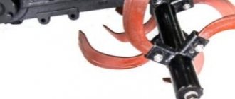
Device "Gnutik"
Purchased or made independently, the “Gnutik” is a universal device that allows you to obtain an arc or angle from a rod. It consists of a base with a slider, on which a stop with an angle (90° or another as necessary) and two cylindrical fixed stops are fixed. By moving the slider and the angle stop, the rod bends at an angle. To obtain an arc, a third cylinder is provided, rotating on the side opposite to the angle stop.
The device can be made on a horizontal or vertical platform.
Axonometry of the "Gnutik" device - vertical arrangement
To scale the dimensions, here is a drawing of the bottom bar of this “Gnutik”.
Bottom bar
This device is universal. With the help of attachments you can not only bend, but also cut and punch holes. But this will be the next step.
Getting an arc on "Gnutik"
Getting an angle on "Gnutik"
This is what a homemade “Gnutik” looks like:
Functionality check
This is always implied, so no comment.
In principle, making a snail for cold forging is not so difficult. Moreover, there is no single standard for such devices.
Someone will say – isn’t it easier to buy a factory model? Firstly, as already said, you will have to search for a long time. Secondly, it is not a fact that her capabilities will coincide with the fantasies of the master.
Thirdly, you will have to lighten your wallet by about 19,000 (manual) and 62,000 (electric model) rubles, at a minimum.
Good luck in making your own snail!
Step-by-step technological process for making a reverse curl on the “Snail” machine
The rolling rollers perform sequential crimping of the pipe. Protruding ribs are formed, and the weld remains inside the layer, offset to the center.
The pipe ends are compressed on parallel eccentric rollers. It becomes like a stripe. In this form it is easier to fix it on the machine.
The shank is formed in a special device. Now the workpieces will be fixed on the machine in one movement.
The workpiece is fixed in the center. There is a groove that secures the shank. It can be seen that the spiral has a uniform descent in height.
After fixing the shank, the electric motor is turned on. Forming of the part begins.
The loop is formed when the workpiece touches a special support element. It is more often called the support shaft. To reduce the force, it is equipped with a bearing. The part rotates freely around the support.
Part of the spiral is formed. But if it is necessary to process for a longer length, a removable element will be installed.
A blank is also formed from the other end. Here the master determines in which direction to bend the part.
To continue work, a removable element of the “Snail” assembly is installed.
Now you can form the bend of large parts.
Even long workpieces are easily bent to specified dimensions. Marks are made on the work items. They are used to guide how much to bend.
On the reverse side, additional bending of the part is performed.
The product is being finalized on both sides.
The finished part has a finished appearance. If necessary, the shanks will be sawed off. Then no one will guess how the workpieces were fixed.
If you need to make a small part, then use another “Snail”. Experienced craftsmen have several of them.
"Globe" device
Such a device is similar in appearance to a school protractor and is designed for making arcs with a large bending radius from a strip, square, circle or hexagon. First, one end of the workpiece is fixed with a bend, then it is bent along its entire length according to the template. The principle of operation is somewhat similar to the operation of a canning machine.
Appearance of the device
Video of work at Globus
Using purely muscle power, a large diameter arc can be made on a template screwed or welded to a workbench. It is good for bending strips, thin-walled pipes, etc.
Sample
Types of machines
The parameters, setup variations, and manufacturing aspects of the equipment vary widely. Based on their identification, designated classes are formed. It is worth understanding that only some of them are available for amateur production, the rest function only in factory conditions.
Torsion bar
This is an analogue of the previous type of equipment, but based on an I-beam and a clamp. In the center there are vise rollers that pass the structure through themselves. The twisting is stronger and more intense. However, not all categories of products can be processed using the indicated method. For example, hollow and round products will not withstand pressure and will be incorrectly deformed.
Machine "Gnutik"
This is a simple DIY cold forging machine. It consists of two shafts, which in a certain way press the part passing through the middle. They are mounted on a static surface, and a wedge is placed in the center. Its task is to make a depression when the shafts begin to move.
Machine "Volna"
Often this manufacturing method is used in production. Therefore, such devices are often purchased in specialized stores, rather than created using artisanal methods. But there is nothing complicated about this either.
You will need a metal flat base and a couple of disks. By passing the material through themselves, they create that same wave on it. One of the disks will be the master, the second remains passive. That is, movements are carried out only by the first element. However, they do not have to be identical in size.
Press
This type of equipment is suitable if you are making flat objects. In fact, these are just two shafts that press the part together, without adding grooves or recesses. In this case, the product can still be made non-uniformly flat if the shafts themselves are corrugated. In this case, the gap between them is slightly increased so that they do not get into each other’s threads.
Materials for making a roller pipe bender
To assemble the mechanism you need:
- 2 steel rollers 10 cm and 6 cm in diameter. Inner radius – 12.7 mm, thickness – 35 mm;
- 1.5-inch thick-walled (from 3 mm) steel pipe for constructing a lever (length from 1.5 m);
- 4 steel strips 15x6 cm, about 5 mm thick. The mechanism for fastening the device in a vice. Also used for the construction of handles and lever supports;
- steel strip 6 cm wide and 3 mm thick;
- 2 bolts – 60 mm 17.78 mm and 40 mm 12.7 mm. For fixing the rollers;
- steel plate 30x30 cm (thickness from 3 mm);
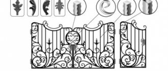
Examples of products with curls
Original canopy over the entrance to the building:
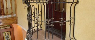
When decorating a French balcony, original curls give an openwork look to the entire product.
On a flight of stairs, the curls look very original.
Using only curls, they make supports for the bench, and also create a grate for the fireplace in the same style.
The hand of an excellent craftsman is visible on the spiral staircase. Not everyone will be able to make such a product.
The gate leaf contains elements made on the “Snail” machine. The heavy product acquired a special lightness.
Light staircase in high-tech style. It can decorate not only a country house. Modern palaces with minimalist design can have an excellent appearance.
The scope for creativity is unlimited. Many blacksmiths are true artists. They decorate the world around them.
Construction of a pipe jack bender
Weld the corners vertically onto the station. Make holes in the channels for installing rollers.
Weld channels onto the corners (2 corners - 1 channel). Place the channels with the platforms facing each other. The spacing between parts should correspond to the length of the rollers. Mount the rollers in the prepared holes and secure with bolts.
How to choose an air conditioner for your home or apartmentDo-it-yourself bait - composition, application features and storage methods (115 photos and videos)
DIY sliding gates - how to build simple and automatic gates. Schemes, drawings and review of the best ideas (90 photos)
Mount the equipment in the shape of a semicircle on the jack and place it in the central part of the base between the channel structures.
Next, lay the pipe at the bottom of the rollers and press it using a jack. As you press, the pipe will bend into the required position.