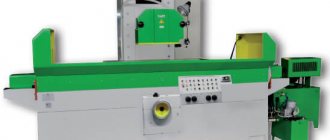
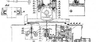
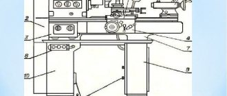
Technical characteristics of the machine 2N135
The technical characteristics of the 2N135 machine are the main indicator of the machine’s suitability for performing certain jobs. For vertical drilling machines, the main characteristics are:
- largest diameter D of drilling the workpiece (parts)
- spindle overhang
- the greatest distance from the end of the spindle to the working surface of the table
- table working surface dimensions
- spindle revolutions per minute
Below is a table with the technical characteristics of the 2N135 screw-cutting lathe. More detailed technical characteristics of the screw-cutting lathe can be found in the passport of the machine 2N135
| Name of parameters | Unit. | Quantities |
| The largest drilling diameter in steel 45 GOST 1050-74 | mm | 35 |
| Spindle cone dimensions according to GOST 25557-82 | Morse 4 | |
| Distance from the spindle axis to the column guides | mm | 300 |
| Maximum spindle stroke | mm | 250 |
| Distance from spindle end to table | mm | 30-750 |
| Distance from spindle end to plate | mm | 700-1120 |
| Maximum (installation) movement of the drilling head | mm | 170 |
| Spindle movement per rotation of the steering wheel | mm | 122, 46 |
| Working surface of the table | mm | 450x500 |
| Maximum table travel | mm | 300 |
| Installation size of the central T-shaped groove in the table according to GOST 1574-75 | mm | 18H9 |
| Installation size of the outer T-shaped grooves in the table according to GOST 1574-75 | mm | 18H11 |
| Distance between two T-slots according to GOST 6569-75 | mm | 100 |
| Number of spindle speeds | 12 | |
| Spindle speed limits | rpm | 31,5-1400 |
| Number of innings | 9 | |
| Feed Limits | mm/rev | 0,1-1,6 |
| Highest number of holes cut per hour | 55 | |
| Cycle management | manual | |
| Type of supply current | three-phase | |
| Supply voltage | IN | 380/220 |
| Main motor type | 4A1001.4 | |
| Main motor power | kW | 4 |
| Electric cooling pump type | X14-22M | |
| Electric cooling pump motor power | kW | 0,12 |
| Electric cooling pump performance | l/min | 22 |
| Machine height | mm | 2535 |
| Machine width | mm | 835 |
| Machine length | mm | 1030 |
| Machine weight | kg | 1200 |
Device design and features
The device of this type of unit includes the following elements:
- spindle;
- gearbox;
- base, workplace and column;
- drive unit;
- head for securing the tool;
- electrical cabinet;
- cooling system;
- gearbox;
- system that controls speeds and feeds;
- plunger oil pump.
Plunger oil pump
The technical characteristics of vertical drilling machines indicate their versatility. These devices can perform not only drilling, but also countersinking, reaming, threading and reaming of holes.
This is due to the use of durable and hard tools made from well-cutting steels.
The ability to cut threads with machine taps is ensured by the reversibility of the spindle, thanks to which it can move in both directions.
The main features of the device are as follows:
- machine weight - 1199 kg;
- spindle torque can reach a maximum of 399 Nm;
- presence of a spindle stop system;
- the maximum permissible force at which the feed is performed is 15 kN;
- the use of an electric pump of the X14-22M type as part of the structure to transfer the cooling liquid to the processing site;
- The dimensions of the desktop are 449*499 mm, on the surface of which there are three grooves in the shape of the letter “T”.
One of the main technological features of the machine is its 100% manual control. All stages of work are adjusted manually, and the spindle feed is carried out mechanically.
General characteristics of the unit include three large parts:
- workplace-table on which the part to be processed is located;
- stable cast iron frame with space inside for electrical equipment;
- a drilling head with a spindle that moves vertically using a worm shaft.
Drilling machine data sheet 2N135
This operating manual “ Passport of the drilling machine 2N135 ” contains information necessary both for the maintenance personnel of this machine and for the employee directly involved in working on this machine. This manual is an electronic version in PDF format of the original paper version. This documentation contains the Passport and Manual (instructions) for the operation of the 2N135 vertical drilling machine.
Content
- General information
- Basic technical data and characteristics
- Contents of delivery
- Procedure for transporting and installing the machine
- Safety instructions
- Machine composition
- Design and operation of the machine and its components
- Pneumatic system
- Lubrication system
- Machine installation procedure
- Operating procedure of the machine
- Possible malfunctions and methods for eliminating them
- Features of disassembling and assembling the machine during repair
- Operating instructions
- Certificate of conservation
- Packaging Certificate
You can download for free “Passport, Manual, Operating Instructions for the vertical drilling machine 2N135” in good quality from the link below:
You can download the second version of “Passport, Manual, Operating Instructions for the vertical drilling machine 2N135” for free in good quality from the link below:
Operation and repair
The operation of the device begins with its column, which performs the function of fixing it on the floor surface. The column is made of cast iron. The work table, which is attached to the column, moves together with the drilling head using a manual drive.
The movement occurs along the column itself. The plate, which plays the role of the base, has an internal cavity in which a special cooling liquid is located. A sump tank is also installed there. An electric pump system is attached to the upper part of the base plate, with the help of which, during operation of the machine, coolant is supplied to the workpieces.
The feed box is installed separately in a special housing located in the working head.
The second main technique for operating the 2n135 machine involves operating the feeder. It includes the following elements:
- 2 couplings, one of which is ratcheting, the other is overrunning;
- steering wheel for control;
- rack-and-pinion gear located on a horizontal shaft;
- worm-gear;
- limba having divisions.
Limba
Thanks to the feeder, the scheme of working with the machine implies a wide range of actions:
- switching off, switching on feed;
- cutting threads on the product itself using the manual feed method;
- spindle retraction upwards from the workpiece;
- bringing the processing tool to the product manually;
- performing advance feed manually.
The mechanism works as follows: the jaw clutch is driven by a rotating handwheel. The clutch then drives a gear, which is connected to a rack, which feeds the spindle.
All this is done manually. When the processing tool impacts the workpiece, the gear rotates. Movement occurs along the axis of the shaft until the moment when the cams of the coupling itself are opposite each other. At this moment the clutch turns 2000.
In cases where the machine was repaired, it is necessary to check its components. It is important to ensure that there are no traces of corrosion on the device. After repair work, the unit runs idle, and the cutting tool is not installed. During a test run, the operation of the device is checked against the data in its technical passport.
Operating manual for electrical equipment of drilling machine 2N135
This “ Operation manual for electrical equipment of the vertical drilling machine 2N135 ” contains information necessary both for the maintenance personnel of this machine and for the employee directly involved in working on this machine. This manual is an electronic version in PDF format of the original paper version. This documentation contains the Manual (instructions) for operating the electrical equipment of the 2N135 vertical drilling machine.
Contents of this documentation:
- Description of the operation of the electrical circuit
- Brief characteristics of electrical equipment
- Electrical power supply system
- Initial Startup Information
- Description of operating modes
- Instructions for using electrical equipment
- Information about interlocks, alarm system, protection and grounding
- Safety instructions
- Electrical circuit diagram
- Electrical connection diagram
- Electrical connection diagram
- Relay block electrical connection diagram
You can download the “Operation manual for electrical equipment of the vertical drilling machine 2N135” for free in good quality from the link below:
You can download the second version of the “Operation manual for electrical equipment of the vertical drilling machine 2N135” for free in good quality from the link below:
Operating principle
Operation of the machine in operating mode occurs according to the following principle. The workpiece to be processed must be installed and securely fixed on the working surface of the coordinate table. The spindle with the installed tool should be located in the lowest position. Using the worktable longitudinal displacement system, the spindle must be centered.
Then you need to make sure that the end of the part to be processed and the spindle are coaxially positioned. Based on the kinematic possibility , in the high-speed gearbox we select the rotation speed suitable for processing. We turn on the vertical electric motor of the main drive.
After setting up the kinematic diagram, the tool head moves to the end of the workpiece, and the desired technological operation is performed.
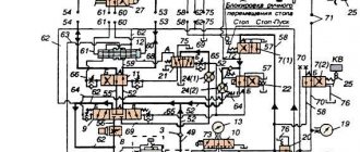
Electrical circuit diagram of a vertical drilling machine 2N135
The electrical circuit diagram of the 2N135 vertical drilling machine is shown in the following figure:
You can download the electrical circuit diagram of the 2N135 vertical drilling machine for free in good quality from the link below:
The electrical circuit diagram of the second version of the 2N135 vertical drilling machine is shown in the following figure:
You can download the electrical circuit diagram of the second version of the 2N135 vertical drilling machine for free in good quality from the link below:
Modifications
To process holes of various diameters, basic units 2N135 are used. At the same time, based on the basic model, the manufacturer offers a number of modified devices. You can determine the intended purpose of a particular machine by the last letter in its name. Improved models include:
- 2N135A - a unit equipped with an automatic control system. The operator controls the operation of the equipment using push-button controls.
- 2N135K is a coordinate-type unit equipped with a cross table.
- 2N135-1 - a coordinate machine with a round table that rotates around the axis of the column.
- 2N135S is a 1-position device with a flanged quill, which allows you to fix heads for several spindles.
- 2N135N is a multi-position device, which provides the ability to fix multi-spindle heads and tables rotating around the axis of the column.
- 2N135F2 – equipment with numerical program control. This modification also provides for the presence of a turret, a cross table and other additional options.
Drilling equipment
In the machine park, a large percentage is occupied by the segment of drilling machines. This is explained by the need to carry out drilling in almost any technological process. All the necessary information related to the design of the unit is contained in the passport supplied with any model of the unit.
All equipment in this segment consists of three groups, each of which is distinguished depending on the specifics of the work:
- special;
- specialized;
- universal.
In each of these groups, gradation can be made depending on the size of the drill, and, accordingly, the holes that a given drilling machine can handle. Let's highlight the main ones:
- light, up to 12 mm;
- medium, 18-50 mm;
- heavy, over 50 mm.
This is interesting: Presses for squeezing juice from apples, grapes, fruits and berries: types, making your own
Design features
The design of the drilling machine consists of:
- The working head, which serves to secure the tool.
- Drive unit.
- Plunger type oil pump.
- Cooling system for the treated area.
- Spindle.
- Gearbox.
- Unit power supply system, electrical cabinet for connecting to the network.
- Gearbox.
- Speed and feed control system.
- Base plate, column, work table.
The unit frame is made in the form of a monolithic, massive, cast-iron structure. The position of the productive surface is carried out by the operator on the supporting column manually, by pressing the locking device and turning the steering wheel, which performs the function of adjusting the position of the spindle. To move the table surface, special guide grooves are made on the column.
The base plate is also cast iron. It has a hollow structure, inside of which there is a container for storing cooling liquid. There is also a settling tank for large metal contaminants and a filtration device. On the support column itself there is an electric pump with a power of 120 W, which is responsible for supplying the liquid. The coolant is supplied through a system of tubes of various diameters, which supply water directly to the drilling element.
The power unit of the machine is located on the top of the body. The spindle block and gearbox of the machine are located in the housing. The kinematic diagram of the equipment has a simple design solution, in which the power unit and the speed box are connected by a straight shaft. Mechanical speed adjustment is carried out using a handle located on the front side of the drilling head. Speed adjustment is done manually. The box transmits spindle rotation speed at twelve frequencies.
The operating elements of the unit are lubricated using a plunger pump in automatic mode. The operator will only need to monitor the oil level using the sensor located on the front panel.
This model has a manual spindle feed system. This system includes:
- A steering wheel that performs an adjustment function.
- Worm-like transmission.
- Overrunning ratchet and dog clutch.
- Limba.
- Shaft, horizontal, with rack and pinion gear.

