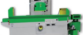
Surface grinding machine 3B722 with a rectangular table and a horizontal spindle
3B722 machine , a longitudinal grinder with a rectangular table and a horizontal spindle, is designed for grinding the planes of various parts with the periphery of a wheel, both in individual and large-scale production. The parts to be ground, depending on the material, shape and size, can be fixed either on an electromagnetic plate, or directly on the working surface of the table, or in special devices.
Surface grinding machine 3B722 – Everything for dummies
Details Category: Grinding machines
A universal surface grinding machine with a rectangular table and a horizontal spindle, model ZB722 (Fig. 1), is designed for grinding the planes of parts using the periphery of a wheel. Depending on the material, shape and size, the parts to be sanded can be fixed either on an electromagnetic plate or directly on the working surface of the table.
Download documentation
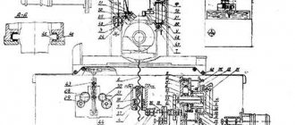
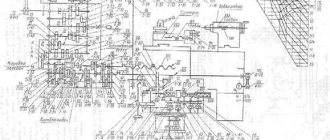
Kinematic diagram
The movement from flywheel A (Fig. 6) is transmitted through gears 1.2, cam clutch B, conical pair 3.4 to nut 5 connected to lead screw 6. Since the nut is fixed against vertical movement, when it rotates, screw 6 will move in the axial direction, feeding the carriage with the grinding headstock.
Bed and table
A table 2 carrying a cylinder 3 moves along the guides of the frame 1 (Fig. 7). The frame guides, which open when the table moves, are closed by two flexible tapes 4. The tapes pass into the table windows formed by the table body and the screwed guides 5. The ends of the tapes are stretched and fixedly fixed to the ends of the bed. When the tape is tensioned, the nuts 6 are released and by rotating the screw 7, the block 8 with the tape attached to it is moved down, after which the nuts 6 are tightened again. In order for the tapes to adhere to the frame guides when the table moves, there are rollers 9 rotating on axes 10, secured in screwed strips 11.
Column
Column 1 (Fig. 8), screwed to the bed frame 2, is a rigid cast frame with guides along which, using a system of rollers 3 located in the separator 4, the carriage 5 moves. Backlash in the guides is eliminated by adjusting the strips 6 and the wedge of the carriage 7 .For visual control of the size of the sanded product, an indicator 8 and a bracket 9 with an adjustable stop are provided.
Vertical feed mechanism
The vertical feed mechanism (Fig. 9a, 96) is mounted on the front panel of the frame 1 and closed with covers 2 and 3. The cylinder of the feed mechanism 4 is attached to the body 5. To increase the durability of the ratchet mechanism, the pawl 6 is made in the form of an asterisk with six teeth. Replacing a worn tooth with a new one is done by turning the pawl. To enable accelerated movement, half-coupling 7 is moved by lever 8 to the extreme right position, at which flywheel 9 is disconnected from the mechanism. The cam 10 turns on the limit switch 11, preparing the accelerated movement from the electric motor. Accelerated movement is only possible as long as the button is pressed. To eliminate the gap in the gearing of the drive, the movement of the overlap 12 gears 13 and 14 are made double. In the sleeve of the folding hard stop 15, a pin 16 is fixed, which abuts against the stationary block 17, which determines the constant position of the folding stop. The gears are lubricated by oil flowing from the guides frame along tube 18 and gathering at the bottom of the body.
Sector 19 is used to automatically stop feeding after removing the established processing allowance. Rotating together with dial 20, sector 19 covers the swing zone of pawl 6, gradually reducing the feed to zero.
Propeller drive support
The screw drive support (Fig. 9 a) serves to transmit movement from the vertical feed mechanism to the column gearbox. The support body 21 is mounted on the mating plane of the pedestal 22. The gear shaft 23 rotates on two bevel roller bearings. The bevel gears 23 and 24 are lubricated by gravity through a tube 25.
Column reducer
The column gearbox (Fig. 9 a) serves to transmit movement from the vertical feed mechanism through the screw drive support to the carriage. The gear shaft 23 of the screw drive support rotates the bevel gear 24, which sits on a key on the bimetallic nut 26. When the nut 26, fixed in the axial direction by means of two angular contact and thrust bearings, rotates, the screw 27 receives vertical movement. Carriage 28 also moves along with the screw. The nut-lead screw pair is lubricated through tube 29 from the lubricator mounted on the carriage.
Carriage
The carriage is an intermediate unit that serves to implement two mutually perpendicular movements of the grinding headstock; vertical and transverse. Vertical movement is carried out along the guides of the column 1 using a screw 2, fixedly attached to the jumper 3 connecting the vertical guides of the carriage.
The horizontal guides of the carriage serve to move the headstock transversely using a cylinder 4 fixed in the carriage or manually using the flywheel 5 through the worm gear 6 of the carriage reducer and a rack and pinion pair. The rack is mounted on the body 7 of the grinding headstock. To carry out the hydraulic movement of the headstock, the worm is disengaged from the gear by turning the handle 8 of the eccentric sleeve 9. In this case, the eccentric 10 through the lever 11 will move the locking spool of the grinding headstock reverse box, opening the way for the oil to the cylinder. When manual movement is turned on, the eccentric 10 will move the locking spool to the other side, connecting both cavities of the cylinder with the drain. At the front end of the carriage there is a disk, gear 12, engaged with gear 14, which sits on the roller 15. A shallow screw groove is cut into the roller, into which includes a pin roller 16 mounted on the body of the grinding headstock. During the full transverse stroke of the grinding head, disk 12 makes an incomplete revolution. The adjustable stops 17 mounted on the disk act on the lever 18, turning it together with the handle 19 and the shaft 20, which, through levers 21 and 22, moves the control spool of the hydraulic reverse gearbox of the grinding headstock. With each reverse, lever 21 alternately turns on the limit switches 23, which give a command to the vertical feed mechanism. The handle 19 can be used to manually reverse the headstock, regardless of the position of the stops 17.
Inside the carriage there is a pipeline that supplies oil to the hydraulic reverse gearbox of the grinding headstock, to cylinder 4 and drains the oil to drain into the tank. The carriage also contains a lubrication pipeline for the grinding headstock guides and a lubricant distributor 25, which receives oil from the lubricator 26.
Grinding head
The grinding head (Fig. 12) moves along the carriage using cylinder 1 or manually from a rack and pinion gear. Spindle 2 rotates on two self-aligning three-liner plain bearings. Inserts 3 and 4 are adjustable, and insert 5 is non-adjustable. Oil is supplied to the bearing area from the lubrication unit. When the spindle rotates, oil gets under each of the liners, forming an oil wedge; this ensures fluid friction between the spindle and the liners. The formation of oil wedges is facilitated by the shape of the outer surfaces of the liners, outlined with a smaller radius than the radius of the hole for the liners in the body of the grinding headstock. Thanks to this, the liners can rotate and self-align in a plane perpendicular to the spindle axis. The inserts are adjusted with screws 6 and 7 so that they fit against the spindle journals along the entire length of the generatrices. In a cold state, the gap between the spindle and the liners should be in the range of 0.04-0.06 mm. The size of the gap can be checked with an indicator when pressing the free end of the spindle with a lever. In the axial direction, the spindle is held by a thrust bearing consisting of two bronze rings 8 and 9 installed in the flange 10. The axial gap in the support is adjusted using a compensation ring 11. To protect against oil leakage from the bearing area outwards on the rear support there is a seal in the form of a bronze ring 12 and a sealing collar 13. The bronze ring is pressed against the end of the spindle by springs 14 and is kept from rotating by a pin 15. On the front support the role of a seal is performed by bronze rings 8 and 9. Oil leaked through seal, flows back into the tank through the drain channels. The spindle rotates from the electric motor through a needle clutch 16. The circle is installed between flanges 17 and 18 and tightened with bolts 19. The circle is protected from splashing of coolant and in case of rupture by a casing 20. A rack is mounted on the headstock body 21 Mechanisms for manual transverse movement of the grinding head and bracket 22 for the cylinder rod. Shield 23 serves to protect against splashes and is adjustable in height with screws 24. Wedge 25 adjusts the gap in the guides of the grinding headstock. Pressure switch 26 controls the supply of lubricant to the spindle bearings. When you press the “Start” button of the grinding wheel, the electric motor of the lubrication installation is turned on, and the oil begins to flow into the grinding headstock. After 15-30 seconds, the lubrication zone is filled with oil and the specified pressure is established. The pressure switch turns on the electric motor of the grinding wheel.
The “Start” button of the grinding wheel must be kept on until the spindle begins to rotate.
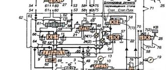
Limit switch box
The limit switch box (Fig. 13) is used to supply electrical commands with each reverse of the grinding headstock to implement intermittent automatic vertical feed. In housing 1 there are two limit switches 2 and pushers 3, which are acted upon by levers 4 and bearing rollers 5. The rollers are in one in one direction the limit switches are turned on by the action of finger 6 on them, and in the other direction they rotate freely on their axes. Thus, one of the switches gives a command during the forward, and the other during the rear reverse of the grinding head. Screws 7 adjust the switching moment.
Hydraulic circuit
Electrical diagram
By turning the handle of the input switch P (Fig. 27), voltage is supplied to the electrical control circuit. Pressing the ZKU button turns on the ZK contactor and the electric motor of the ZM lubrication pump. When the pressure in the lubrication system rises, the contacts of the microswitch of the pressure switch RD close at points 9—11, supplying power to contactor 1K along the circuit 3—5—7—9—11—12. Contactor 1K with its power contacts turns on the electric motor 1M, and with contacts 7-9 it becomes self-powered. Electric motors 1M and 3M are stopped by pressing the 2KU button. Normally the machine works with an electromagnetic plate. In this case, the 2P switch is set to the “Work with the stove” position and its contact at points L14-43 is closed, and at points 5-19 it is open. By pressing the 4KU button, the contactor 4K receives power, thereby turning on the electric cooling pump 4M. The 1P switch carries out various options for turning on the electric pump: a) turning on the electric pump with the grinding wheel (contacts 9-15 are closed); b) turning on the electric pump from button 4 KU (5-13); c) turning on the electric pump with hydraulics (23-15); d) turning off the electric pump. Buttons 7KU and 8KU turn on contactors 5K or 6K, reverse rotation of the electric motor 5M and the corresponding movement of the grinding head “Up” or “Down”. By turning the switch handle P of the electromagnetic plate to the “On” position, contacts PZ-P1 (L 1-J12) are closed. and P2—P4 (CI—C2), and the electromagnetic plate PE receives power through the circuit P1—PZ—P5—P4—P2. At the same time, the PC serial relay is activated, which, with its contact 5-19, prepares the 2K contactor circuit for switching on and with contact 61-62 turns on the JTC signal lamp - “The stove is on.” By pressing the 6KU button, the 2K contactor is turned on and contact 21-23 becomes self-powered; contacts in the main circuit turn on the 2M electric motor. To remove the product from the electromagnetic plate, switch handle P must be moved to the “Demagnetized” position and released. Under the action of the spring, the handle will return to the zero position. In the zero position, contact P5-P6 closes and contacts P1-PZ and P4-P2 open. The electromagnetic plate is disconnected from the selenium rectifier and shunted with a 2C resistance. The PC serial relay turns off and turns off the LS signal lamp. In the “Demagnetized” position of the switch handle P, contact P5-P6 opens and contacts P1-P4 and P7-P2 close, a current of reduced strength in the reverse direction flows in the coils of the electromagnetic plate due to the presence in the circuit resistance 1C. A short-term pulse of reverse polarity is necessary to demagnetize the electromagnetic plate and, partially, the parts being ground. When the machine is operating without turning on the electromagnetic plate or when the electromagnetic plate is removed from the machine, switch 2P is set to the “Work without plate” position. Contact 2P closes at points 5-19, and opens at points L14-43 and breaks the switching circuit of the selenium rectifier. Switch 2B turns on and off the vertical supply of the grinding wheel to the product. In the “On” position of switch 2B, the grinding wheel is supplied to the workpiece automatically during the grinding process. By pressing the limit switch 1KV or 2KV in one of the extreme positions of the grinding headstock, the vertical feed electromagnet 1E or 2E is turned on and the grinding wheel is fed by a certain amount. Switch 1B turns on and off the local lighting lamp L0.
Download documentation
forkettle.ru
Machine 3L722V. Surface grinding. Specifications
Technical characteristics of machines are the main indicator of the suitability of the machine for performing certain jobs on the machine. For surface grinding machines, the main characteristics are:
- Dimensions of the working surface of the machine
- The largest dimensions of the sanded product
- Table longitudinal movement speed
- Circle speed
Below is a table with the technical characteristics of the 3B722 surface grinding machine. More detailed technical characteristics of the machine can be found in the passport of the machine 3B722, which can be downloaded below.
| Quantities | ||
| The shortest distance from the spindle axis to the working surface of the table | mm | 190 |
| The largest distance from the spindle axis to the working surface of the table | mm | 630 |
| Largest dimensions of installed products (LxWxH) | mm | 1000x360x400 |
| Largest dimensions of processed surfaces (LxW) | mm | 1000x320 |
| Dimensions of the working surface of the table (LxW) | mm | 1000x320 |
| Dimensions of the working surface of the electromagnetic plate (LxW) | mm | 900x320 |
| Speed limits for longitudinal table movement | m/min | 2…40 |
| Speed limits for continuous transverse movement of the grinding headstock | m/min | 0,5…3 |
| Spindle speed | rpm | 1460 |
| Grinding wheel motor power | kW | 10 |
Attention! The technical specifications given in the above table are for reference only. Machines produced by different manufacturers and in different years may have characteristics that differ from those given in the table.
Machine 3B722. Surface grinding. Manual. Electrical equipment
This manual “3B722. Surface grinding machine. Manual. Electrical equipment" contains information necessary both for the maintenance personnel of this machine and for the employee directly involved in working on this machine. This manual is an electronic version in PDF format of the original paper version.
Content
Purpose and scope of application of the machine Unpacking and transportation of the machine Machine passport Electrical equipment of the machine
- General information
- Description of the operation of the electrical circuit
- Turning on spindle lubrication
- Turning on the grinding wheel rotation
- Turning the electromagnetic cooker on and off
- Turning on the hydraulics
- Enabling automatic vertical feed
- Turning on the coolant pump and magnetic separator
- Rapid raising and lowering of the grinding headstock
- Turning on the lights
- Blocking
- Protection
- Instructions for operating the electric drive
- Safety instructions
- Instructions for use and maintenance of electrical equipment
- Operation of electrical equipment
- Possible malfunctions and methods for eliminating them
- Electric motor care
- Fuse Care
- Caring for magnetic starters, control relays and electromagnets
- Caring for thermal relays
- Caring for circuit breakers
download the Operation Manual for the electrical equipment of the 3B722 surface grinding machine in good quality from the link below.
Design features of the machine
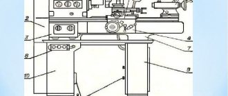
Appearance
The installation consists of a horizontal frame, on the surface of which there are guides, on which the workpiece is attached. During operation, a displacement is performed in the horizontal longitudinal direction. For processing large workpieces, slight shifts in the transverse direction are possible. The grinding wheel is fixed on the headstock. This aggregation unit can move in a vertical plane.
For normal operation of the equipment, the design includes 6 electric motors. The main drive of the headstock spindle is carried out by transmitting torque from a 10 kW power unit. For accelerated vertical displacement, a 1.1 kW electric motor is used. The remaining drive devices are designed to ensure the operation of the cooling systems and magnetic separator.
The 3B722 surface grinding machine has the following specific characteristics:
- methods of fixing parts. They can be flooded on the workbench by mechanical devices or by an electromagnetic plate;
- the grinding head moves along a stand with horizontal guides;
- the design contains rolling screw pairs;
- digital display system that controls the degree of displacement of the grinding wheel.
The presence of high-precision bearings ensures uniform processing of the material over the entire surface.
The design of the spindle unit allows you to select optimal operating modes - feeds and changing the speed of the work table. The sound power level should not exceed 99 dB.