16D20 — Screw-cutting lathe
Specifications:
Model 16d20 machines are designed for a variety of turning operations on centers and chucks.
Length, mm 3880 Width, mm 1270 Height, mm 1605 Machine accuracy class according to GOST 8-82, (N, P, V, A, S) N Main movement motor power, kW 11 Machine weight, kg 3 100 CNC type and capacity tool magazine — Spindle rotation speed min/max, rpm 8.5/2,000 Diameter of part above the support, mm 210 Diameter of the workpiece above the bed, mm 400 Length of the workpiece, mm 1,500
Machine characteristics
- lathes
- drilling machines
- boring machines
- grinding machines
- sharpening machines
- electrical machines
- gear cutting machines
- thread processing machines
- milling machines
- planing machines
- slotting machines
- broaching machines
- cutting machines
- other equipment
KPO characteristics
- mechanical presses
- hydraulic presses
- bending and straightening machines
- forging machines and rollers
- scissors
- automatic forging and pressing machines
- hammers
- equipment complexes based on forging and pressing machines
- automatic production lines
- mechanization and automation devices for forging and pressing equipment
- Various forging and pressing equipment
Characteristics of imported equipment
- Lathes
- Drilling machines
- Boring machines
- Grinding machines
- Sharpening machines
- Electroerosion machines
- Gear processing machines
- Milling machines
- Forging and pressing equipment
- Other equipment
- Pipe processing machines
- Band saws
- Machining centers
- Honing machines
Characteristics of Electrical Equipment
- High voltage devices (over 1000 V)
- Low voltage devices
- Powder metallurgy products
- Cable products
- Integrated control devices for electric drives. Electric drive
- Complete control, electrical energy distribution and protection devices for voltages up to 1000 V
- Medical equipment
- Pumping equipment (pumps, pumping units and installations)
- Air conditioning and ventilation equipment
- Semiconductor devices and converters based on them
- Instruments and automation equipment for general industrial purposes
- Lighting products
- Power capacitors and capacitor units
- Technological equipment
- Transformers (autotransformers). Complete transformer substations. Reactors
- Traction and crane electrical equipment
- Ultrasound equipment
- Chemical and physical current sources
- Electric cars
- Electrical insulating materials
- Electroceramic products, insulators
- Electric welding equipment
- Electrothermal equipment
- Electric coal products
Characteristics of pumping equipment
- Vacuum pumps
- Drainage, sand, slurry pumps
- Pumping stations, installations and motor pumps
- Drum pumps
- Water pumps
- Pumps for wells and wells
- Fuel pumps
- Chemical and aggressive media pumps
- Fecal pumps
- Other surface pumps
- Other submersible pumps
- Other self-priming and circulation pumps
- Other pumps
Steel and alloy grades
- Ferrous metals, steels, cast iron
- Non-ferrous metals and alloys
- Other steels and alloys
- Foreign analogues
Other equipment
News
02/10/19 — Added characteristics for refrigeration equipment
01.11.17 — Added characteristics for pumping equipment
02/16/17 — Updated specifications for the KA4537 press
Share information
Didn't find the specifications for the equipment you need on the portal? Send us a model of equipment that we do not have, and we will notify you as soon as we add the characteristics of this equipment to the site.
Lathe 16d20 technical specifications
Screw-cutting lathes 16D20, 16D20P, 16D20G, 16D25, 16D25G can be used in various industries in various operations for processing different materials. Maintenance of machines should be carried out taking into account the specifics of their operation.
The machine is designed to perform various turning operations and cutting metric, modular, inch and pitch threads. The workpieces are mounted on centers or a chuck. Machine accuracy class N, P. When finishing parts made of structural steel, the roughness of the machined surface is V6b. Deviation from cylindricity is 7 microns, taper is 20 microns at a length of 300 mm, deviation from straightness of the end surface at a diameter of 300 mm is 16 microns. The machine replaces the 1K62 model. In all quality indicators (productivity, accuracy, durability, reliability, ease of maintenance, operational safety, etc.) it is superior to the machine model 1K62. A rigid box-shaped frame with hardened, ground guides is installed on a monolithic base. The spindle is mounted on precision rolling bearings. The support has scale rulers with sights for easy determination of the amount of movement of the cutting and cross slides during operation. New toolholder design improves clamping stability. The machine apron is equipped with an original mechanism for switching off the feed of the caliper, which ensures high stopping accuracy on a rigid stop. A complex of fencing and blocking devices guarantees safe operation of the machine. It is most advisable to use the machine in tooling and repair services in small-scale and single-piece production for finishing and semi-finishing work. Machines 16D20P, 16D20G, 16D25, 16D25G are made on the basis of the main 16D20 with maximum unification, have the same kinematic diagrams and a unified design.
Kinematic diagram
The spindle rotates from a reversible electric motor Ml through an automatic transmission and a bulkhead box connected by poly-V belt drives. The automatic transmission installed on the machine has six electromagnetic clutches, the activation of which in a certain sequence allows you to obtain nine speed steps and brake the machine spindle. With the help of inclusions of gears 16, 19, 20 and 22, the selector box gives the first stage, gears 18, 25, 26 and 21 the second stage, gears 17, 24, 26 and 21 the third stage of rotation speed. Thus, the spindle has 27 rotation speeds. The kinematic feed chain starts from the machine spindle. The feed rate or thread pitch is determined per spindle revolution. From the spindle, through gears 21, 26, 23, 29 and the main set of replaceable gears K, L, M, N, rotation is transmitted to the input shaft of the feedbox. Next, the feed movement passes through the feed box and rotates the lead screw when cutting threads or the lead shaft for all other types of processing. Through transmission 23, 28 and 27, 29 we get all left-hand threads. Through gears 26, 32 we get doubling of feeds and right-hand threads. Through gears 17, 24 and 23, 29, with gear 26 disengaged, we obtain feeds increased by 16 times. Additionally, when hooking 23, 30, we get II thread on I”; at 23, 31, we get 19 threads on I". The rotational movement of the lead screw or drive shaft is converted by the apron mechanism into longitudinal and transverse feeds. Using tables 4, 5, they set the feed rates and configure the machine for cutting various threads.
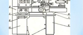
bed
The machine bed is box-shaped with U-shaped ribs, has two prismatic and two flat guides. A spindle head, a feed box, a bracket 5 for a lead screw 2 and a lead screw 4, as well as a rack 3 are installed on the frame.
In the niche of the right end of the frame, an electric motor for fast movements of the caliper is located on the submotor plate 6. The plate can move on rolling pins 7.
For machines 16D20G and 16D25G, the bed is made with a recess that allows processing parts with a diameter of 630 and 700 mm, respectively. In this case, the bed has an insert I. If it is necessary to process parts of larger diameter, the insert is reduced. To do this, you need to unscrew the plugs I, remove the screws 2 and pins 4. To avoid nicks, the liner 3 must be placed on a lining made of soft material and coated with a thin layer of oil to prevent corrosion. Before installing the liner on the frame, you should thoroughly wipe the seating surfaces of the frame and liner, inspect and make sure there are no nicks on them.
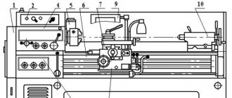
Layout of components of screw-cutting lathe 16D20, 16D20P, 16D20G
Location of the main components of the screw-cutting lathe 16d20
Specification of components of screw-cutting lathe 16D20, 16D20P, 16D20G
- Left casing 16D20.420000.000
- Control panel 16D20.181000.000
- Cartridge guard 16D20.421000.000
- Carriage 16D20.050000.000; 16D20P.050000.000
- Four-position tool holder 16D20.041.001
- Electrical equipment 16D20.180000.000
- Caliper 16D20.040000.000; 16D20P.040000.000
- Cooling 16D20.410000.000
- Rear guard 16D20.425000.000
- Tailstock pneumatic equipment 16D20.120000.000
- Rear headstock 16D20.030000.000
- Apron 16B20P.061000
- Base 16D20.016000.000; 16D20G.018.000.000
- Spindle head 16D20.020000.000-01
- Feed box 16D20.070000.000
- Bulkhead box 16D20.028000.000
- Feed box lining 16D20.071000.000
- Gearbox 16D20.080000.000
- Control cabinet 16D20.190000.000
- Panel 16D20.200000.000
- Caliper guard 16D20.423000.000
- Lubrication station 16D20.401000.000
- Motor unit 16D20.150000.000
- Pulleys and tables 16D20.157000.000
- Automatic transmission 16D20.083000.000
16D20 Universal screw-cutting lathe
Characteristics
| The largest diameter of the workpiece processed above the bed, mm | 400 |
| The largest diameter of the workpiece processed above the support, mm | 220 |
| The largest diameter of the workpiece processed above the recess (designation D), mm | 630 |
| Maximum length of the installed RMC part, mm | 750, 1000, 1500 |
| The largest mass of the processed product in the centers, kg | 1300 |
| Spindle hole diameter, mm | 63 |
| Spindle tool taper, mm | M80 |
| Spindle flange, mm | 6M |
| Main drive drive power, kW | 11 |
| Spindle speed, rpm | 8,5..2000 |
| Number of forward spindle speeds | 27 |
| Number of speeds switched without stopping the spindle | 9 |
| Maximum torque on the spindle, kN*m | 2 |
| Cutter height, mm/rev | 25 |
| Longitudinal feed range, mm/rev | 0,05..10,7 |
| Transverse feed range, mm/rev | 0,025..5,35 |
| Number of feeds longitudinal/transverse | 32/ 32 |
| Speed of rapid movements longitudinal/transverse, m/min | 4/ 2 |
| Limits of metric thread pitches, mm | 0,5..112 |
| Limits of pitches of inch threads, threads/inch | 0,25..56 |
| Limits of modular thread pitches, module | 0,5..112 |
| Limits of pitch thread pitches, diametric pitch | 56..0,25 |
| Tailstock quill center according to GOST 13214-79 | M5 |
| Maximum movement of the quill, mm | 150 |
| Number of electric motors on the machine | 3 |
| Main motion electric motor, kW | 11 |
| Electric motor for fast movements, kW | 0,75 |
| Coolant pump electric motor, kW | 0,125 |
| Electric motor of hydraulic station, kW | — |
| Machine dimensions (length width height) (RMC = 1000), mm | 2880 x 1270 x 1605 |
| Machine weight, kg | 2800 |
Description
Equipment
Analogs
Ask a Question
These machines have been discontinued, but we will definitely find analogues for you!
The developer and manufacturer of the 16D20 screw-cutting lathe is the Alma-Ata Machine Tool Plant, founded in 1932 as iron foundry No. 1 of the regional department of light industry.
16D20, 16D20P, 16D20G Universal screw-cutting lathe. Purpose and scope:
Screw-cutting lathes 16D20, 16D20P, 16D20G, 16D25, 16D25G can be used in various industries in various operations for processing different materials. Maintenance of machines should be carried out taking into account the specifics of their operation.
The machine is designed to perform various turning operations and cutting metric, modular, inch and pitch threads. The workpieces are mounted on centers or a chuck.
You can ask any question you are interested in about the product or work of our company.
Our qualified specialists will definitely help you.
Information about the manufacturer of the screw-cutting lathe 16D20
The developer and manufacturer of the 16D20 screw-cutting lathe is the Alma-Ata Machine Tool Plant , founded in 1932 as iron foundry No. 1 of the regional light industry department.
Since April 1942, after merging with the foundry-mechanical plant, evacuated from Lugansk, it began to be called the Alma-Ata Mechanical Plant N21 named after. 20th anniversary of the October Revolution of the People's Commissariat of Medium Engineering of the USSR.
In 1945, the Alma-Ata Machine Tool Plant named after. 20th anniversary of October.
The plant produced screw-cutting lathes: 16D20, 16D20P, 16D20PF1, TV16, 16D25, 1D95, 1E95, 1M95.
Machine tools of the plant Alma-Ata Machine Tool Plant named after. 20th anniversary of October
- 1D95
– combined screw-cutting lathe Ø 400 - 1E95
– combined screw-cutting lathe Ø 400 - 1M95
– combined screw-cutting lathe Ø 500 - 16D20
– screw-cutting lathe Ø 400 - 16D25
– screw-cutting lathe Ø 500 - 16E20
– screw-cutting lathe Ø 400 - TV-16
table lathe Ø 160
Technical characteristics and diagrams of the screw-cutting lathe 16B20
Universal screw-cutting lathe 16B20. The maximum turning diameter is 445 mm, the version with a recess in the bed is up to 620 mm. Details in the article.
The 16v20 screw-cutting lathe can be called a direct descendant of the famous first-born of the Soviet machine tool industry DIP-200, the first “successor” of which is the 1A62 lathe. In 1949, production of the 1A62 was transferred from the flagship of the Soviet machine tool industry in Moscow to the newly created Astrakhan Machine Tool Plant. Seven years later, the company stopped producing its first-born and began production of a new lathe model developed on its basis, which had two modifications: 16V20 and 1V62G.
16B20 was produced as part of Soviet national economic plans and was intended for use in small repair enterprises and workshops on collective and state farms. The operating instructions of the 80-90s directly indicate its purpose: use “at repair or ... agricultural enterprises.” 16B20 is one of the long-lived members of a large family of Soviet machine tools: it is still produced by the same plant and under the same index. True, now in his lathe documentation it is written that it is intended for use in “various ... enterprises, including repair ones.”
Main technical characteristics
The 16B20 screw cutting machine was produced in three standard sizes with center-to-center distances of 750, 1000, 1500 mm. Other technical characteristics of the machine (linear dimensions in mm):
- distance from the center axis to the guides - 222.5;
- distance from the center axis to the carriage - 110;
- spindle hole diameter - 54;
- maximum carriage stroke - 900;
- maximum slide stroke - 280;
- maximum extension of the quill - 150;
- maximum spindle speed - 1400 rpm;
- main drive power - 7.5 kW.
In terms of its technical characteristics, the 16B20 screw-cutting lathe is similar to the 16K20. One of its main differences is the diameter of the turning above the guides increased by 45 mm.
Description of the electrical circuit of the machine 16D20. General information
Three-phase squirrel-cage asynchronous electric motors are installed on the machine and the following voltage values are applied
- power circuit ~ 380 V, 50 Hz;
- AC control circuit ~ 110 V, 50 Hz
- DC control circuit - 24V
- local lighting circuit ~ 24 V; 50 Hz
- alarm circuit - 24 V
The work area is illuminated by a carriage-mounted gooseneck light with a 40 W lamp.
The apron handle has a built-in switch to control the fast movement electric motor. The main drive electric motor control panels are located on the spindle head and carriage.
The control cabinet is mounted on brackets above the automatic gearbox. The supply wires are entered through the hole in the control cabinet with a wire with a cross-section of 4 mm2 (black for linear wires and green-yellow for grounding wires).
On the front side of the control cabinet there are the following machine controls:
- NZ - signal lamp with a milky lens, signaling the on state of the input switch;
- H4 - warning lamp with a milky lens, indicating the presence of automatic transmission lubricant;
- S2 light switch;
- S8 cooling pump switch off button;
- S9 cooling pump activation button;
- P - load meter
Passport
The passport of the 16B20 lathe is included in the “Operating Instructions” supplied with it. Basic information about the released and tested copy of the machine is given in the chapter “Acceptance Information”. Its first part is devoted to checking electrical equipment. At the beginning there is the model, serial number and manufacturer of the electrical cabinet, and at the end there is the signature of the person responsible for testing it.
The next section contains data on conservation, indicating the date of this operation, state standards and the validity period of conservation, and at the end there is the signature of the person in charge. This is followed by packaging information (also signed by the person in charge), and the chapter ends with the “Acceptance Certificate” section. It indicates the designation, modification and serial number of the machine, but does not contain a table with technical test data, which in earlier times usually completed the lathe's passport. Instead, a list of GOSTs and technical specifications is provided, the requirements of which it fully complies with based on the results of “inspection and tests”.
YOU CAN DOWNLOAD YOUR PASSPORT HERE.
Workspace dimensions
The capabilities of processing a part on turning equipment depend on the placement of its components and mechanisms relative to each other, as well as the maximum strokes of its moving parts. The combination of these parameters determines the dimensions and configuration of the working space of the lathe. Among them, the most significant are the length of the turning along the center-to-center axis, as well as the height of the latter above the guides and carriage.
For a 16B20 lathe (with a RMC of 1000 mm), these values are 900, 445 and 220 mm. Its technical characteristics do not indicate the maximum weight of the workpiece, which, although not a geometric parameter, can seriously limit the size of possible processing.
Design features
Structurally, the 16B20 lathe practically repeats the well-known 16K20, which is not surprising, since both of them originate from the same “ancestor”. Many parts and components of these machines are interchangeable, although their performance qualities are noticeably higher in the Moscow machine, according to many reviews.
Among users of lathes of this class, there is a widespread opinion about the low service life of 16B20 components and mechanisms, which is associated with the reduced strength of the steels used and weak hardening (or even its absence). In addition, many turners note the non-rigidity of its design, the small size of the windows on the bed, which makes it difficult to remove chips, as well as the fastening of the upper slide with two bolts. And the main advantage is always the increased processing diameter compared to 16K20.
Specification of main components
In the “Product Composition” section of the documentation for the 16B20 lathe, the following list of its main components is provided:
- Electrical cabinet
- Front grandma.
- Rear grandma.
- Chuck guard.
- Transmission.
- Gearbox.
- Carriage and support.
- Apron.
- Caliper guard.
For an additional fee, the machine can be additionally equipped with a mechanized support and two types of steady rests: movable and fixed.
Location of controls
The composition and location of the 16B20 controls is traditional for such turning equipment. Power switches with indicator lamps are located on the top of the headstock, and knobs for selecting the direction and speed of spindle rotation are located in a row on its face. Directly below them are the feed box controls.
A handwheel for manual movement of the carriage, a double-sided handle for moving the slide, a push-button block for general activation and a high-speed button are mounted on the apron of the machine. On the carriage and support there is a handle for moving the tool slide, as well as a lever for turning and clamping the tool holder.
Kinematic diagram
The kinematic diagram of the 16B20 lathe implements both main movements and auxiliary moves, as well as movements related to preparatory and final operations. Some of these movements are performed mechanically, and some are performed manually.
The main kinematic chain begins with the drive pulley and includes the gearbox mechanisms. The kinematic feed chain receives movement from the output shaft of the gearbox and, through a set of replaceable gears, transmits it to the apron and then to the carriage and caliper. In this way, reliable kinematic synchronization is achieved between the specified spindle rotation and the cutter feed.
Electrical diagram
The 16B20 screw-cutting lathe is famous for the simplicity and reliability of its electrical equipment, which consists of an electrical cabinet and the following electrical circuits:
- power nutrition;
- signaling devices;
- lighting of the work area;
- control switching devices.
All circuits are powered from a workshop AC source. The motors operate from a three-phase voltage of 380 V, the switching circuits from a single-phase voltage of 110 V, and the lighting devices from a voltage of 24 V.
Electrical equipment is protected from short circuits by fuse links and automatic switches, and protection from heating during overloads is implemented using thermal relays. The machine also uses zero protection starters, which cut off the power supply when the voltage drops below 85% of the nominal value. An integral element of the electrical circuit is grounding, which must be connected when installing the equipment.
Location of controls for screw-cutting lathe 16D20, 16D20P, 16D20G
Location of the main components of the screw-cutting lathe 16d20
List of controls for screw-cutting lathe 16D20
- Handle for setting feeds and right-hand threads (handle F)
- Light switch
- Automatic transmission lubrication warning lamp
- Handle for setting the spindle speed range (handle E)
- Signal lamp (power indicator)
- Handle for setting left-hand threads (handle G)
- Cooling pump start and stop buttons
- Cooling pump start and stop buttons
- Load indicator
- Spindle speed table
- Spindle speed setting handle (roller switch)
- Emergency switch
- Duplicate main drive control handle
- Oil button for lubrication of cross slides and clamping bars
- Handle for turning and fastening the cutting head
- Manual cross feed handle
- Emergency switch
- Main drive control unit
- Handle for manual movement of the cutting slide
- Button for enabling fast movements of the carriage and support
- Tailstock quill fixation handle
- Handle for attaching the tailstock to the frame
- Tailstock quill moving handle
- Tailstock Cross Screw
- Handle for controlling the strokes of the carriage and caliper
- Lead screw nut engagement handle
- Lead Screw Nut Engagement Symbol Label
- Bolt securing the carriage to the frame
- Rack and pinion on/off handle
- Handwheel for manual carriage movement
- Feed or thread setting knobs
- Feed and thread type selection handle
- Feed or thread setting knobs
- Thread and feed table
- Table of additional and precision threads
- Input switch
Safety precautions
The operating instructions for the 16B20 lathe contain a voluminous chapter entitled “Safety Instructions”, consisting of eight sections. The first of them contains a description of safety measures during storage, transportation and installation of the lathe in its intended place.
The most voluminous is the second section, dedicated to putting the 16B20 lathe into operation. Here, special attention is paid to compliance with all requirements when connecting equipment to the electrical network, especially checking the condition of external and internal grounding circuits. This section also describes in detail the composition and procedure for checking protective and blocking devices, the main ones being:
- spindle locking device when the chuck guard is open;
- external protective screen;
- device for blocking spontaneous activation of spindle control handles;
- caliper protection;
- protection of the lead screw and shaft;
- device for blocking the activation of the main drive when the cover of the gearbox mechanisms is open;
- device for protecting the apron from overloads.
The following section describes the safety requirements when performing turning operations on 16B20. First, we once again remind you of the need to maintain the protective and interlocking devices listed in the previous section. The following provides detailed instructions for the safe performance of various technological operations. It also contains links to GOST and departmental documentation, the requirements of which must be observed to ensure the safety of turning operations.
Section 4 contains safety requirements for monitoring the technical condition of a lathe, section 5 covers repairs and maintenance, sections 6 and 7 describe safe interaction with adjacent equipment and adjacent work areas, and section 8 sets out fire safety requirements. The modern instructions for the 16B20 lathe indicate that it is designed in accordance with the equipment safety standard TR TS 010/2011. And in the instructions of Soviet times, Appendix N3 is a standard instruction on labor protection when working on metal-cutting machines.
Repair of machine 16D20. Typical repair work performed during scheduled repairs
During the period between repairs, the machine must be subjected to six inspections, four minor repairs and one medium repair within the time limits specified in the recommended schedule of planned repairs (Fig. 42).
It should be taken into account that the greatest efficiency in using a machine can be ensured by rational alternation and frequency of inspections and scheduled repairs, carried out taking into account the operating conditions specific to each individual machine.
Categories of machine repairability:
- mechanical part - 12;
- electrical part - 8.5.
Machine inspection
External inspection without disassembly to identify defects of the machine as a whole and in units.
Checking the strength and density of fixed rigid connections (base with foundation; bed with base; headstock; feed box with bed; carriage with apron; pulleys with shafts, etc.).
Opening the covers of units for inspection and checking the condition of the mechanisms.
Removing play in the screw pair of the cross slide drive.
Checking the correct switching of spindle speeds and feeds.
Adjustment of the friction clutch of the main drive and the spindle band brake.
Checking the condition and minor repairs of the lubrication system.
Checking the condition, cleaning and minor repairs of enclosing casings, shields, etc.
Identification of worn parts that require restoration or replacement during the next scheduled repair.
Inspection before major repairs
Work performed during inspections before other types of repairs and, in addition, identifying parts requiring restoration or replacement, sketching or ordering drawings of worn parts from assemblies undergoing disassembly.
Note. During the inspection, those of the listed works are performed, the need for which is determined by the condition of the machine.
Minor lathe repair
- Partial disassembly of the spindle head, feed box, apron, as well as other most contaminated components. Opening covers and removing casings for internal inspection and washing of other components.
- Cleaning the mounting surfaces for fixtures on the spindle and tailstock quill without dismantling the latter.
- Checking the gaps between shafts and bushings, replacing worn bushings, adjusting rolling bearings (except spindle bearings), replacing worn ones.
- Adjusting the main drive friction clutch, adding discs, adjusting the spindle band brake.
- Removing burrs from gear teeth and splines.
- Replacement or restoration of worn fasteners and adjusting parts of tool holders.
- Scraping or cleaning of adjusting wedges, clamping bars, etc.
- Cleaning the lead screw, lead shaft, transverse and tool slide drive screws of the caliper.
- Cleaning and washing the seating surfaces of the cutting head.
- Checking the operation and adjusting the levers and handles of controls, blocking, locking, safety mechanisms and limiters; replacement of worn crackers, pins, springs and other parts of the specified mechanisms.
- Replacement of worn parts that are unlikely to withstand use until the next scheduled repair.
- Cleaning nicks, burrs, burrs and scratches on the rubbing surfaces of the bed guides, carriages, caliper slides and tailstock.
- Repair of enclosing casings, shields, screens, etc.
- Repair and flushing of the lubrication system and elimination of leaks.
- Regulating the smooth movement of the carriage and caliper slide; tightening the wedges of the clamping bars.
- Checking the condition and cleaning of gear couplings.
- Checking and repairing pneumatic equipment and cooling systems; eliminating leaks.
- Identification of parts requiring replacement or restoration during the next scheduled repair.
- Checking the accuracy of machine installation and selectively other accuracy parameters.
- Testing the machine at idle speed at all speeds and feeds, checking for noise, heating and on the workpiece for accuracy and cleanliness of processing.
Note. For minor repairs, those of the specified works are performed that are caused by the condition of the machine being repaired, with the exception of the work provided for in the last three paragraphs, which must be performed in all cases.
Average repair of lathe 16D20
- Check for accuracy before disassembly.
- Measuring the wear of rubbing surfaces before repairing base parts.
- Partial disassembly of the machine.
- Washing, wiping parts of disassembled units, washing, cleaning of dirt from undisassembled units.
- Monitoring the rigidity of the spindle assembly (see paragraph 13.1.5).
- Replacement or restoration of worn bushings and rolling bearings.
- Replacing or adding friction discs and replacing the spindle brake band.
- Replacement of worn gears and couplings.
- Restoration or replacement of worn screw pairs of the caliper slide drive and tailstock quill.
- Replacement of worn fasteners.
- Replacement or restoration and adjustment of adjusting wedges and clamping bars.
- Restoring the accuracy of the lead screw (by cutting).
- Checking and cleaning unworn parts left in the machine mechanisms.
- Repair of the coolant supply pump and fittings.
- If the hinge mechanism of the lamp NKS 01 x 100/POO-03 wears out, unscrew the base, turn it counterclockwise 90° and secure it again.
- Repair of the lubrication system pump, equipment and fittings; repair or replacement of oil indicators, gaskets, plugs and other elements of the lubrication system.
- Correction by grinding or scraping guide surfaces in need of repair if their wear exceeds the permissible level.
- Repair or replacement of protectors on the carriage, caliper slide, tailstock.
- Repair or replacement of enclosing panels, casings, screens, etc.
- Assembling repaired components, checking the correct interaction of components and all machine mechanisms.
- Painting external non-working surfaces with putty.
- Running in the machine at idle speed at all speeds and feeds.
- Check for noise and heat.
- Checking the machine for compliance with accuracy standards.
Overhaul of lathe 16D20
- Checking the machine for accuracy before disassembling.
- Measuring the wear of rubbing surfaces before repairing base parts.
- Complete disassembly of the machine and all its components.
- Washing and wiping all parts.
- Inspection of all details.
- Clarification of a previously compiled (during inspections and repairs) list of defective parts requiring restoration or replacement.
- Restoration or replacement of worn parts.
- Cooling system repair.
- Replacing the lubrication system pump and repairing it.
- Grinding or scraping the guide surfaces of the bed, carriage, caliper slide, tailstock.
- Replacement of protectors on the carriage, caliper slide, tailstock.
- Assembling all machine components, checking the correct interaction of components and mechanisms.
- Puttying and painting of all unfinished surfaces in accordance with the finishing requirements of new equipment.
- Running in the machine at idle speed at all speeds and feeds.
- Check for noise and heat.
- Check the condition of the foundation, correct it and install the machine in accordance with section 4 of this manual.
Lathe 16K20: technical characteristics and analogues
The screw-cutting lathe 16K20 belongs to the category of universal metal-cutting equipment, suitable for performing a number of operations. The machine was produced in the period from the early 70s to the mid-80s by Moscow. Currently, only used units are on the market, but due to its reliability, low price and ease of maintenance, it is still widely used today for training purposes, in repair shops, as well as in production and repair shops for single and small-scale production of parts.
Capabilities of the 16K20 machine
The design characteristics of the 16K20 lathe allow it to be effectively used for turning surfaces with a workpiece length of up to 2000 mm and a weight of up to 1300 kg of both cylindrical and conical shapes. It can also be used for cutting workpieces, preparing holes, preparing various types of threaded connections - metric, inch, modular and pitch.
The machine's capabilities allow you to produce threads with different pitches. Thus, it is possible to cut modular and pitch threads with a pitch of 0.5 to 56, inch threads with a pitch of 0.5 to 112 threads per inch, and metric threads with a pitch of 0.5 - 112 mm. The screw-cutting lathe has an accuracy class H, ensures a deviation from cylindricity of no more than 7 microns, conicity - no more than 20 microns per 300 mm, end surface - 16 microns per diameter of 300 mm.
Design features of the machine 16K20
Let us note the main features and advantages of the machine, thanks to which it is still one of the most reliable and popular solutions for equipping repair and production workshops:
- The box-shaped frame is placed on a massive, monolithic base, which ensures the rigidity of the entire structure.
- High precision movement of the caliper and movable tailstock thanks to reliable guides.
- Possibility of fixing the workpiece in the chuck or by clamping in the centers.
- Reliable fixation of the cutter thanks to the design of the holder.
- High-precision spindle bearings guarantee high-precision positioning and rotation and do not require adjustment during operation.
- High security thanks to a range of fencing and locking elements. Emergency caliper shutdown.
- The headstock mechanism allows for four rows of spindle rotation numbers.
- The output shaft of the headstock is rigidly connected to the feed box through the engagement of replaceable gears. This ensures precise movement of the caliper from the lead shaft or lead screw depending on the operation.
- High precision of operations due to the presence of a ruler with sights for effectively checking the longitudinal and transverse movement of the cutting tool.
You can study the main technical characteristics of the 16K20 machine in the table below:
| Technical characteristics of the machine 16K20 | Options |
| Machining diameter above the bed, mm | 400 |
| Machining diameter above the support, mm | 220 |
| Distance between centers | 1000 / 1500 |
| Accuracy class according to GOST 8-82 | N |
| Size of the inner cone in the spindle | Morse 6 M80* |
| Spindle end according to GOST 12593-72 | 6K |
| Diameter of through hole in spindle, mm | 55 |
| Maximum weight of the workpiece fixed in the chuck, kg | 300 |
| Maximum weight of the part fixed at the centers, kg | 1 300 |
| Number of spindle rotation stages, pcs. | 23 |
| Number of spindle reverse rotation frequency steps | 12 |
| Frequency limits for direct spindle rotation, min-1 | 12,5 — 2 000 |
| Spindle reverse rotation frequency limits, min-1 | 19 — 2 420 |
| Number of working feed stages - longitudinal | 42 |
| Number of working feed stages - transverse | 42 |
| Limits of working feeds - longitudinal, mm/rev | 0.7 — 4,16 |
| Limits of working feeds - transverse, mm/rev | 0,035-2,08 |
| Number of metric threads cut | 45 |
| Number of inch threads cut | 28 |
| Number of modular threads to be cut | 38 |
| Number of pitch threads cut | 37 |
| Number of threads to be cut - Archimedean spiral | 5 |
| Maximum torque, kNm | 2 |
| Maximum movement of the quill, mm | 200 |
| Transverse displacement of the housing, mm | ±15 |
| Largest cutter section, mm | 25 |
| Main drive motor power | 10 kW |
| Electric motor power for fast movement of the caliper, kW | 0.75 or 1.1 |
| Cooling pump power, kW | 0,12 |
| Overall dimensions of the machine (L x W x H), mm | 2,812 / 3,200 x 1,166 x 1,324 |
| Machine weight, kg | 3 035 |
The design of the machine ensures high operational safety, reliability, simplicity and ease of maintenance. All this, along with low cost, guarantees its demand on the Russian market.
Brief description of assembly units
Machine base
The base of the machine consists of a bed mounted on two and three (for machines with RMC = 2000 mm) pedestals.
bed
The machine bed is box-shaped with U-shaped ribs, has two prismatic and two flat guides. A spindle head, a feed box, a bracket 5 for a lead screw 2 and a lead screw 4, as well as a rack 3 are installed on the frame.
In the niche of the right end of the frame, an electric motor for fast movements of the caliper is located on the submotor plate 6. The plate can move on rolling pins 7.
For machines 16D20G and 16D25G, the bed is made with a recess that allows processing parts with a diameter of 630 and 700 mm, respectively. In this case, the bed has an insert I. If it is necessary to process parts of larger diameter, the insert is reduced. To do this, you need to unscrew the plugs I (Fig. 13), remove the screws 2 and pins 4. To avoid nicks, the liner 3 must be placed on a lining made of soft material and coated with a thin layer of oil to prevent corrosion. Before installing the liner on the frame, you should thoroughly wipe the seating surfaces of the frame and liner, inspect and make sure there are no nicks on them.
To process parts above a recess in the bed, it is necessary to use a special elongated cutter or a cutting mandrel installed in the tool holder, as shown in Fig. 14. Mandrel 3 is installed in tool holder 4, cutter I is fastened with screws 2.
ATTENTION! When processing parts above a recess, the spindle speed should not exceed 400 min-1.
Cabinets
The machine stands are cast and hollow. The main movement electric motor is installed in the left cabinet, and an oil tank for centralized lubrication is attached to the right end.
The right cabinet contains a pump and a tank for coolant.
A retractable trough is installed between the pedestals on rollers to collect chips and coolant.
Bulkhead box
The transfer box is attached to the rear end of the spindle head and is a gearbox in which the machine spindle serves as the output shaft. The gear mechanism of the pick-up box allows for three ranges of spindle rotation speeds; increase the gear ratio between the feed chain and the spindle by 2 and 16 times; cut right-hand and left-hand threads; additionally cut inch threads II and 19 threads into I”, divide when cutting multi-start threads into 2, 3, 4, 5, 6, 12, 15, 20, 30, 60 starts.
The gears are switched using handles through cams and levers.
The moving gears move along splined shafts based on the inner diameter.
Lubrication of the bulkhead box is centralized, described in section 8
Headstock
The spindle head is mounted on the horizontal plane of the frame guides on its left side with six bolts. The spindle head is a rigid cast iron casting with one bore, in which the machine spindle is mounted in cylindrical cone roller bearings:
- 4-697920Л1 front support for normal precision machines
- 2-697920L1 front support for high-precision machines according to GOST 21512-76
- 4-17920L rear support for normal precision machines
- 2-17920L rear support for high-precision machines according to GOST 21512-76
ATTENTION! Spindle bearings are adjusted at the machine manufacturer's factory and do not require additional adjustment.
Motor installation
The motor installation consists of a main motion electric motor, a motor plate 9 and a guide rod 3.
The motor plate is mounted on the left end of the right pedestal with two clamps 7 and screws 4, 8. Rotation from the main motion electric motor is transmitted by a poly-V-belt to an automatic transmission - AKP 309-16, which is mounted on the rear wall of the pedestal.
Analogues of the machine
The 16K20 screw-cutting lathe replaced the 1K62 model, surpassing it in all quality indicators. After it was discontinued, domestic and foreign manufacturers produced numerous analogues of the 16K20 machine with various additions. These are MK6056, MK6057 and MK6058 (Red Proletary, Moscow), 16VT20 and 16VT20P (Vistan, Vitebsk), 16B16, 16B16P, 16B16V and 16B16A (SVZS, Samara) and many other models. Thanks to many analogues and high standardization of parts, there is no shortage of spare parts and equipment to ensure uninterrupted operation of the 16K20 machine.
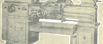
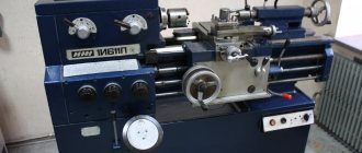
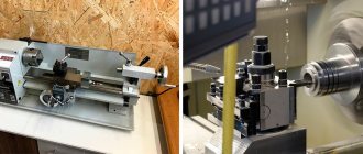
General view of the screw-cutting lathe 16D20, 16D20P, 16D20G
Photo of screw-cutting lathe 16d20
Photo of screw-cutting lathe 16d20
Photo of screw-cutting lathe 16d20
Automatic gearbox AKP309-16 of a screw-cutting lathe 16d20
Drive of screw-cutting lathe 16d20