Manufacturer of the screw-cutting lathe 1624M - Frunzensky Machine-Building Plant named after. IN AND. Lenin , founded in 1941. Currently Bishkek Machine-Building Plant.
The plant dates back to November 1941, when an evacuated plant from Voroshilovgrad (now Lugansk) specializing in the production of cartridges opened its doors in the center of the city of Frunze.
Subsequently, over the years of its existence, the plant became a multifunctional enterprise with a developed infrastructure. Having at its disposal machine-tool, forging and foundry, electrical and other facilities, the plant produced a variety of products: cartridges for small-caliber small arms, mechanical presses, CNC lathes, injection molding machines, ARL, electric hoists, lathe chucks, chains for combines, and so on the same as consumer goods.
Machine tools produced by the Frunzensky Machine-Building Plant
- 1A625
- lightweight screw-cutting lathe with increased processing diameter Ø 500 - 6B11
- vertical cantilever milling machine 250 x 1000 - 16B25PSp
- universal screw-cutting lathe with automatic transmission Ø 500 - 1624M
– universal screw-cutting lathe Ø 500 - KV-235
- single-crank sheet metal stamping press 630 kN - FT-11
- universal screw-cutting lathe with automatic gearbox Ø 500
Information about the manufacturer of screw-cutting lathe 1604
The manufacturer of the 1604 lathe is the Odessa Experimental Mechanical Plant , founded in 1946.
The developer of the 1604 lathe is Odessa Machine Tool Plant .
Machine tools produced by the Odessa Machine Tool Plant (OSZ) and the Experimental Mechanical Plant (OMZ)
- 1P611
- high-precision screw-cutting lathe, Ø 250 - 16B05A
- especially high precision screw-cutting lathe, Ø 250 - 16B05P
- high-precision screw-cutting lathe, Ø 250, Kirovakan - 16M05A
- screw-cutting lathe of especially high precision, Ø 250 - 1601
— table lathe Ø 125 - 1604
— high-precision screw-cutting lathe, Ø 200 - 1613D
- precision screw-cutting lathe, Ø 240 x 270 - OT-4
- lightweight high-precision screw-cutting lathe, Ø 250 - OT-5
- high-precision, lightweight lathe-screw-cutting machine, Ø 250
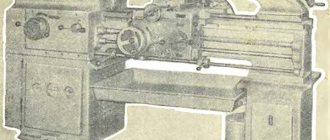
General view of the screw-cutting lathe 1604
Photo of lathe 1604
Photo of lathe 1604
Landing and connecting bases for lathe 1624M
Landing and connecting bases of a lathe 1624m
Screw-cutting lathe bed 1624m
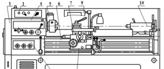
Location of components and controls for screw-cutting lathe 1604
Location of components and controls for screw-cutting lathe 1604
Specification of the main components of the screw-cutting lathe 1604
- 14. CVT
- 15. Cabinet
- 25. Headstock
- 30. Guitar
- 40. Apron
- 45. Caliper
- 50. Tailstock
- 55. Cooling
- 65. Fencing
- 75. Accessories
- 82. Switch
- 83. Electrical equipment
- 95. Lubrication device
Location of controls for screw-cutting lathe 1604
- Handle for changing spindle rotation and braking
- All stop button
- Switch for changing the longitudinal feed amount
- Handle busting
- Collet clamp handwheel
- Bit handle
- Light switch
- Handle for manual lateral movement of the caliper
- Handle for turning the uterine nut on and off
- Quill clamp handle
- Headstock clamp handle
- Handwheel for moving the quill
- Upper carriage movement handle
- Input switch
- Cooling switch
- Overload handle
- Switch for changing the direction of feed and rapid movement of the caliper
- Handwheel for manual longitudinal movement of the caliper
- Handwheel for changing the spindle speed
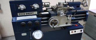
1624M Universal screw-cutting lathe. Purpose and scope
In terms of its design, the 1624m machine is closest to the design of the 1A625
produced by the same plant, developed at the Moscow plant Krasny Proletary.
The 1624m screw-cutting lathe is designed to perform a wide range of turning operations in finishing and semi-finishing modes. It is not recommended to use it in roughing and roughing modes. High spindle speeds make the machine suitable for high-speed operation, while ensuring rational use of modern grades of hard alloys. The machine is adapted for cutting the main four types of threads, and with a reduced kinematic chain of the feed box (direct activation of the lead screw) it makes it possible to cut non-standard threads. The design of the machine provides for two speed ranges.
The presence of preselective control of spindle speeds facilitates and speeds up the process of changing spindle speeds and thereby reduces wasted time.
Design of screw-cutting lathe 1604
Variator of screw-cutting lathe 1604
Variator of screw-cutting lathe 1604
The spindle rotation drive is made in the form of a stepless V-belt variator with sliding pulleys 1 2, 5, 6 moving along shafts 3 and 7 (Fig. 8).
The shafts are mounted on rolling bearings in the bores of the bracket 8, to which the electric motor 9 is attached.
Changing the number of spindle revolutions is carried out only while the machine is running by turning the flywheel 10, the roller 11, the worm 12, which engages with the worm wheel - nut 13, leading to axial movement of the screw - the roller on which the fork 4 is mounted, moving the movable disks 2-5
Headstock of screw-cutting lathe 1604
The headstock is installed and secured to the left of the top of the frame on the plane (Fig. 9). The headstock contains a spindle 6}, a drive 5, a drive for cutting threads 1, a snaffle 11 and a control mechanism 8.
Rotation of the spindle is transmitted from pulley 4 directly through gear coupling 3, or through gear 5. The gear ratio is 1: 8. A double-row roller bearing 7, which takes radial loads, and two thrust ball bearings 9, which take axial loads, are installed in the front support of the spindle. A radial ball bearing is installed in the rear spindle support. The rear support of the spindle 6 and the drive pulley 4 are located in a bracket molded to the headstock housing 12, which allows you to change belts without disassembling the spindle. The thread cutting drive receives rotation from the spindle gear 10 and reduces the rotation speed of the first shaft of the guitar 2 and three times relative to the spindle, and also allows for reversing the guitar when cutting right-hand and left-hand threads.
Using handle 13 on the front cover of the headstock, the thread cutting drive is completely switched off during longitudinal mechanical feed.
Guitar lathe 1604
The guitar (Fig. 10) consists of a body 4 attached to the headstock, a tilt 2 and a cover 1. The tilt rotates on the flange of the output roller 5 of the headstock and is secured in the desired position with a bolt 3. The axis of 7 interchangeable gears 6 is fixed in the groove of the tilt.
Apron for screw-cutting lathe 1604
The apron (Fig. 11) serves to transmit movement to the caliper from the lead screw when cutting threads and for longitudinal feed from a separate electric motor 4 mounted on the side wall of the apron.
The movement from the lead screw is transmitted when the master nut 1 is turned on.
Longitudinal feed is carried out by means of a DC electric motor driven by a magnetic amplifier (control range 1: 14). Engine rotation is transmitted through worm gear 2, 3 and three pairs of gears 8, 9, 10, 11, 13, 14 to rack and pinion gear 5. The apron has an overload clutch 12, an oil pump for lubricating the apron mechanisms, and a longitudinal feed dial 6 is located on the outer wall and handwheel for manual movement 7.
The switching on of the feed and the uterine nut is blocked.
Tailstock of machine 1604
The tailstock has separate guides on the frame and is clamped on it using an eccentric 7 (Fig. 12).
The tailstock quill 4 has a constant direction in the body 3 and moves with the help of a screw pair 1, 2. The quills are marked with divisions that allow you to count the length of movement when drilling. The quill is clamped by handle 5, by turning which the clamping bar 8 is attracted to the plane of the frame.
The transverse displacement of the headstock is carried out by screws 9 and is fixed in the desired position.
Machine support 1604
The machine support is a conventional one, of a cross design, providing movement of the cutter in the longitudinal and transverse directions (Fig. 13).
The backlash in the screw pair 1 is selected using a split nut 2. The cutter is installed in a 4-seater tool holder 3.
Lubrication device
The lubrication device (Fig. 14) is mounted on the front wall of the cabinet 1 and consists of a cast iron body 2, which houses an oil pump 3 driven by an eccentric 4. The eccentric receives rotation from the first shaft 5 of the variator through a belt drive 6.
Fencing
A rack 3 is mounted on the support, along which a slider 2 moves, carrying the visor 1.
It is secured in the desired position with screws 4 (Fig. 15).
Switch
The switch is installed in the niche of the cabinet on plate 8, on which limit switch 1 is mounted (Fig. 16).
By turning handle 9 to the right and left, bar 6 and plunger 4 close the contacts of limit switches 2 and 3 to obtain right or left rotation of the spindle. Springs 5 return the handle to the stowed position, providing zero protection. When the handle 9 is turned toward itself, the plunger 11 acts on the limit switch 10, and the engine is turned off and braked. Handle 9 is returned to its original position by spring 12.
Plunger 7, depending on the direction in which the engine is turned on, occupies a lower or upper fixed position. Limit switch 1 determines the direction of rotation of the motor.
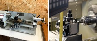
What kind of work is it used for?
It is used in finishing and semi-finishing modes. Should not be used for roughing or roughing work. The machine performs all standard turning operations, and it is also possible to carry out non-standard work depending on the length of the kinematic chain.
Threading
The machine has the ability to cut threads. Depending on the set parameters, it is possible to cut metric, inch, modular and pitch threads, as well as several types of non-standard threads.
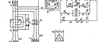
Electrical circuit diagram of screw-cutting lathe 1604
Electrical circuit of screw-cutting lathe 1604
The electrical equipment of the machine contains:
- Asynchronous 3-phase squirrel-cage electric motors for spindle drive 1M, cooling capacity 2M;
- Adjustable electric feed drive operating according to the following scheme: magnetic amplifier - DC motor ;
- Control and protection equipment;
- Local lighting.
Protection of the electrical equipment of the machine:
- Protection of motors and PMU circuits from overload is carried out by thermal relays;
- Protection against short circuit currents is carried out by automatic switches or fuses;
- Zero protection is carried out by starter coils Kl, Kpr;
- Ground the machine to the workshop grounding circuit.
Technical characteristics of screw-cutting lathe 1604
| Parameter name | 1604 |
| Basic machine parameters | |
| Accuracy class according to GOST 8-82 | P |
| The largest diameter of the workpiece above the bed, mm | 200 |
| The largest diameter of the workpiece above the support, mm | 110 |
| Maximum workpiece length (RMC), mm | 350 |
| Maximum length of workpiece turning, mm | 350 |
| Height of centers above the bed, mm | 108 |
| Spidel | |
| Diameter of through hole in spindle, mm | 21 |
| The largest diameter of the processed rod in the chuck, mm | 20 |
| The largest diameter of the processed rod in the collet, mm | 12 |
| Number of speed steps for direct spindle rotation | 14 |
| Frequency of direct spindle rotation without overdrive, rpm | 375..3000 |
| Frequency of direct rotation of the spindle with search, rpm | 47..375 |
| Size of the internal cone in the spindle, M | Moze 4 |
| Spindle braking | There is |
| Caliper | |
| Maximum movement of the caliper longitudinal/transverse, mm | 350/ 115 |
| Number of longitudinal feed stages | |
| Limits of longitudinal working feeds, mm/rev | |
| Limits of working cross feeds, mm/rev | |
| Speed of fast movements of the caliper, longitudinal, mm/min | 190 |
| Speed of fast movements of the caliper, transverse, m/min | No |
| Number of metric threads to be cut | 18 |
| Limits of pitches of cut metric threads, mm | 0,2..3,0 |
| Number of inch threads to be cut | 13 |
| Limits of pitches of cut inch threads | 40..8 |
| Number of modular threads to be cut | 7 |
| Limits of pitches of cut modular threads | 0,3..1,0 |
| Movement by one division of the dial in the longitudinal/transverse direction, mm | 0,5/ 0,02 |
| Diameter and pitch of the lead screw, mm | |
| Running shaft diameter, mm | |
| Longitudinal switch stops | There is |
| Transverse switching stops | No |
| Upper slide | |
| Maximum movement of the slide, mm | 78 |
| Movement of the slide by one division of the dial, mm | 0,02 |
| Movement of the slide per one revolution of the dial, mm | 2,0 |
| Angle of rotation of the sled, degrees | ±45 |
| The largest cross-section of the cutter holder, mm | 12 x 12 |
| Distance from the cutting surface to the center line, mm | 12 |
| Tailstock | |
| Maximum movement of the tailstock quill, mm | 70 |
| Tailstock quill cone, mm | Morse 2 |
| Tailstock quill diameter, mm | |
| Maximum lateral displacement of the tailstock, mm | ±8 |
| Movement of the quill by one division of the ruler, mm | 1 |
| Electrical equipment | |
| Number of electric motors on the machine | 2 |
| Main drive electric motor, kW | 1,0 |
| Cooling pump electric motor, kW | 0,12 |
| Dimensions and weight of the machine | |
| Machine dimensions (length width height), mm | 1310 x 690 x 1280 |
| Machine weight, kg | 440 |
- Universal high-precision screw-cutting lathe 1604. Manual, 1973
- Acherkan N.S. Metal-cutting machines, Volume 1, 1965
- Batov V.P. Lathes, 1978
- Beletsky D.G. Handbook of a universal turner, 1987
- Golovin G.M., Peshkov E.O. Special machines in instrument making, 1952
- Denezhny P.M., Stiskin G.M., Thor I.E. Turning, 1972. (1k62)
- Denezhny P.M., Stiskin G.M., Thor I.E. Turning, 1979. (16k20)
- Lokteva S.E. Computer controlled machines, 1986
- Modzelevsky A. A., et al. Lathes, 1973
- Pekelis G.D., Gelberg B.T. Technology of repair of metal-cutting machines, 1970
- Pikus M.Yu. A mechanic's guide to machine repair, 1987
- Skhirtladze A.G., Novikov V.Yu. Technological equipment for machine-building industries, 1980
- Tepinkichiev V.K. Metal cutting machines, 1973
- Chernov N.N. Metal cutting machines, 1988
Bibliography:
Related Links. Additional Information
- Classification and main characteristics of turning
- Selecting the right metalworking machine
- Multi-start thread. Methods for cutting multi-start threads on a lathe
- Graphic signs for lathes
- Friction clutch of a screw-cutting lathe
- Methodology for checking and testing screw-cutting lathes for accuracy
- Directory of lathe manufacturing plants
- Directory of lathes
Home About the company News Articles Price list Contacts Reference information Interesting video KPO woodworking machines Manufacturers