Electric drill, DIY repair
Second article of the summer competition. This time the author is known to regular readers of the blog. This is Alexey Sidorkin, who already participated in the first competition with an article about a homemade time relay.
Alexey is not only the author of the blog, but an active commentator. His insightful comments under the pseudonym “Alex S” can be found under many articles on SamElectrique.ru.
So, the article by Alexey Sidorkin:
I think every person has had more than one event or incident in their life for which they could not find a suitable explanation, remaining a secret for a long time. This happened with my drill.
My son-in-law Dmitry acquired this Bosch PSB 500 RE drill in May 1998 to furnish his newly acquired apartment. At that time, not everyone had such a prestigious tool (power 500 W, speed control, reverse rotation, impact mode - “hammer”) on the household. The purchase aroused quiet envy - I had a simple Soviet drill without any bells and whistles. My daughter gave the Bosch drill later after the tragic death of her son-in-law during an accident in 2002.
Of course, my use of the tool was not “every day from morning to evening”; the drill was used for everyday needs, as in most ordinary families, plus the summer season at the dacha.
Fig.1. General view of the BoschPSB 500 RE drill.
The drill worked properly, successfully performing all its options and functions... and suddenly 5-6 years ago the speed regulator stopped “obeying” - no matter the position/setting of the regulator wheel/handwheel, when you press the trigger, the drill immediately made full revolutions without any smoothness. The first thing that came to mind as to why there were no low speeds was that the drill’s speed control circuit had burned out. But by that time, other tools appeared on the farm, including a screwdriver and another drill in the village, and the operation of the Bosch drill in low speed mode was not so relevant, and we never got around to fixing the problem.
Just recently I had to carefully work with a drill, and its high speed turned out to be very inappropriate, and there were no other tools with a chuck at hand. Not far from the house there is a workshop for repairing household appliances. They told me that the speed controller (hereinafter referred to as RO) for the Bosch drill is only “made to order”, wait at least 2 months, the cost of work is 500 rubles.
I decided to figure it out on my own, after all, I am a power equipment adjuster [1], albeit retired.
He's an adjuster himself, but he went to the workshop? If it’s urgent, and for a couple of hundred (previously it was called “per bottle”), then there’s no point in “uncovering your rifle,” others should also be allowed to live.
(Author's note)
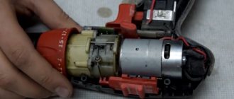
I opened the drill, disconnected the RO (two detachable electrical contacts of the knife type, two “for screws” and one screw securing the power wire - Fig. 2).
Rice. 2. Connecting the speed controller in the drill.
The drill speed controller is a separate unit. In Fig. 3, almost life-size, there are two halves (lid and body) of an already opened RO, the material is plastic, the halves are fixed between each other “with latches.”
Rice. 3. Drill speed controller with cover removed
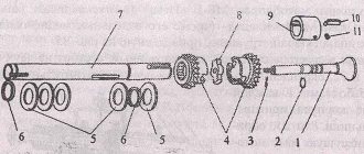
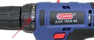
Figure 3 shows: 1 – contact group; 2 – sliding contacts; 3 – resistor strips; 4 – adjusting screw handwheel; 5 – trigger return spring.
The housing of the speed controller for the drill contains a contact group 1 and sliding contacts 2 in the form of two spring plates, driven by pressing the trigger and returning to their original position under the influence of the return spring 5.
The cover contains a capacitor (bottom) and a board (top) with electronic elements and two resistor strips 3, along which, when the trigger is pressed, contacts 2 slide to smoothly change the speed of the tool. A special lubricant is applied to the resistor strips to protect the strips, reduce friction and prevent sparking of the sliding contacts.
An adjusting screw with a handwheel 4 on the trigger limits the depth of the trigger press and the distance/length of sliding of the contacts 2 along the resistor strips 3, thereby determining the range of regulation and the maximum speed of the drill. If the adjusting screw is turned out completely, then the trigger, when fully pressed, closes the contact group to directly turn on the drill motor, bypassing the electronic adjusting elements, and the engine runs at the highest possible speed (3000 rpm).
The drill speed controller circuit is almost identical to the rotary dimmer circuit. The only differences are in design and dimensions.
The scope of my work included checking the precise operation of the trigger when pressed, the interaction of the parts of the contact group, the rotation of the adjusting screw, leveling the distribution of lubricant on the resistor strips, and cleaning accessible areas from accumulated dust and dirt. No malfunctions, malfunctions or suspicious aspects were found. In other words, I carried out a small inspection, after which I assembled the drill, turned it on and... the speed controller started working as if nothing had happened!
Thus, repairing the Bosch drill speed controller was reduced to simple cleaning!
Many assumptions could be made regarding the reasons for the temporary malfunction of the drill - from a blow or an unnoticed fall of the tool to problems with electronic components. However, an analysis of the situation still tends to disrupt the operation of the “sliding contacts - resistor strips” pair for some unknown reason; it is enough for a speck (particle) to simply get under one of the sliding contacts - and that’s it, there will be no adjustment. This is also evidenced by turning on the tool immediately at full speed, which is only possible when the contact group is triggered.
But, whatever you say, it turns out that the instrument turned out to be an electrician himself and repaired it himself!
Why do you need a speed controller?
Typically, mini drills are built on the basis of conventional DC motors.
And the speed of such engines depends on the load and applied voltage. As a result, at idle speed the engine spins very strongly, and during drilling moments the engine speed fluctuates in a wide range. If you reduce the voltage on the motor when there is no load on it, you can achieve an increase in the service life of both the drills and the motors themselves. In addition, even drilling accuracy is improved. The easiest way to achieve this is to measure the current drawn by the motor.
There are many circuits of similar regulators on the Internet, but most of them use linear voltage regulators. They are massive and require cooling. In collaboration with TinyElectronicFriends, we wanted to make a compact board based on a switching stabilizer so that it could simply be “put on” the motor.
Algorithm for finding and eliminating electrical failures
DIY mini drill
If you intend to repair a drill, you must adhere to a certain algorithm, starting with the simplest and most common problems and eliminating them as they are diagnosed:
- If the device does not turn on, you need to open the case and examine the cable contacts with a multimeter. The connection is made to the plug connector and the opposite clamp, after which the cable is bent along its length 2-4 times. If the contact is unstable or absent, the wire inside the insulating coating has broken. If the break is near the edge, the wire can be cut and reconnected. If not, it needs to be replaced.
- If there are no problems with the cord, diagnose the switch by connecting a multimeter to the terminals. Sparking and oxidation of contacts indicate problems. The switch must be disassembled, cleaned of dust, and the contacts must be sanded.
- Inspect the communicators between the switch and the brushes. Then the brushes themselves - they should be pressed well by the springs against the rotor lamellas. If the brushes are worn, they should be replaced. If clogged, remove dust and clean with sandpaper.
- Check for a short circuit between the winding contacts and the housing and measure the resistance. There should be approximately the same indicator on all windings. If on any one it differs by more than 5%, it must be rewound.
Important! Do not check the wire contacts when the voltage is on. This may result in a shock or short circuit situation.
Drill switch
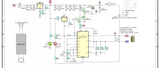
Scheme
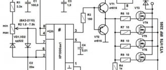
A PWM regulator with a built-in switch MC34063 regulates the voltage on the motor.
The voltage on the shunt R7, R9, R11 is amplified by the operational amplifier and, through a comparator, supplied to the feedback input of the PWM controller. If the current is less than a certain value, then a voltage is applied to the motor, depending on the resistance setting RV1. That is, at idle speed only part of the power will be supplied to the engine, and the trimming resistor RV1 will allow you to adjust the speed at the same time.
If the signal at the output of the op-amp exceeds the voltage on the comparator, then the full supply voltage will be supplied to the motor. That is, when drilling, the engine will turn on at maximum power. The switching threshold is set by resistor RV2. A linear stabilizer is used to power the op-amp.
All components of the circuit will dissipate very little heat and it can be assembled entirely using SMD components. It can operate over a wide range of supply voltages (depending on resistance R6), and does not require controllers or speed sensors.
Question from a reader
Reader Alexander contacted me by email with the following request:
Good evening. I came across your blog where you repair a Bosch drill. I have a similar problem, but I have almost nothing to do with electronics. Stupidly I disassembled the trigger of a Bosch GSB 1600 RE drill. Everything worked great before, I put it together somehow, but now the soft start doesn’t work. Perhaps I’m putting the parts in the wrong order and in the wrong place. I am attaching a photo of the disassembled one. I hope this helps, the drill is good.
Photo of a disassembled Bosch drill button:
Bosch drill repair. The disassembled trigger is a button with a speed control.
Bosch drill repair. Disassembled trigger - button
I don't know how to help the reader. Maybe someone can share their experience?
Links:
I suggest reading a book that describes various curious inventions: Otto Petrik, Curiosities of Technology, Budapest 1985, 150 pp., illus.
If you liked the article, vote for it here and now:
Voting for the authors of the summer competition
- 1. Marchenko Boris Danilovich with articles on welding cores and searching for hidden wiring (49%, 29 Votes)
- 3. Sergey Pikalov with an article about wiring in construction (34%, 20 Votes)
- 2. Alexey Sidorkin with an article about repairing a Bosch drill (17%, 10 Votes)
Total voters: 59
List of components
Here is a complete list of everything needed for assembly:
- Printed circuit board (link to manufacturing files at the end of the article)
- U1 - MC34063AD, switching regulator, SOIC-8
- U2 - LM358, operational amplifier, SOIC-8
- U3 - L78L09, stabilizer, SOT-89
- D1,D3 - SS14, Schottky diode, SMA - 2 pcs
- D2 - LL4148, rectifier diode, MiniMELF
- C1 - capacitor, 10uF, 50V, 1210
- C2 - capacitor, 3.3nF, 1206
- C3, C4 - capacitor, 4.7 µF, 1206 - 2 pcs
- C5 - capacitor, 22uF, 1206
- R1-R3,R7,R9,R11 - 1 Ohm resistor, 1206 - 6 pcs.
- R4, R10 - resistor 22 kOhm, 1206 - 2 pcs.
- R5 - 1kOhm resistor, 1206
- R6 - resistor 10-27 kOhm, 1206. The resistance depends on the rated voltage of the motor used. 12V - 10kOhm, 24V - 18kOhm, 27V - 22kOhm, 36V - 27kOhm
- R8 - resistor 390 Ohm, 1206
- RV1, RV2 - subscript resistor, 15 kOhm, type 3224W-1-153 - 2 pcs.
- XS1 - terminal, 2 pins, pitch 3.81mm
We also made a limiter ring on a 3D printer for easy installation on the engine. The download link for the STL file is at the end of the article.
Drill repair: replacing contact brushes
One of the most common causes of malfunction is wear or burning of the contact brushes. The first signs of brush wear appear in the form of sparking in the contact area of the brushes with the armature of the electric motor and minor malfunctions in the operation of the drill when the load increases.
The location of the contact brushes inside the drill.
Many drill models have simplified access to the brushes, and changing them is not difficult, and some drills require disassembling the body and removing the brush holder. The brushes must be replaced with new ones, equal in size to the failed brushes.
They should fit tightly in the brush holder. The electrical contact of the supply wire must be tightened well. The brush contact with the armature commutator must be reliable. It is necessary to check the action of the spring.
Assembly and configuration
Everything is assembled quite simply.
The contact pads are designed for hand soldering. It is worth starting assembling the board itself by installing all the components on the side of the board without trimmers, and then on the reverse side. It is easier to install the terminal last. The R6 rating is selected according to the rated voltage of your motor. In this device, it is important to control the position of the key on the microcircuits and the polarity of the diodes. All other components are non-polar. Place a spacer between the board and the motor above so that the board does not touch the motor. The board itself is placed directly on the engine lamellas. Check the polarity of the motor connection several times so that it turns to the right, and then solder the contacts.
Contacts for supplying voltage, the board input is labeled “GND” and “+36V”. The negative of the input voltage source is connected to the “GND” contact, and the positive to “+36V”. The power supply voltage must match the rated voltage of the motor.
Setting up the controller is very simple:
- Set the regulator response threshold to the maximum using resistor RV2
- Set resistor RV1 to the optimal engine speed in idle mode
- Set the response threshold with resistor RV2 so that when the slightest load appears, the voltage on the motor increases
Checking the electric motor: causes of breakdowns and repairs
There are several reasons for damage to the armature or stator of a drill. First of all, this is illiterate operation of the device. For example, many users simply overload the tool, working without interruption. This leads to the fact that the drill motor does not have time to “rest”. The second reason lies in poor coil wire, which is often found in cheap models. That is why breakdowns of cheap tools are much more common. In this case, repairs must be carried out using specialized tools. And it will be better if you entrust this work to professional specialists.
However, if you decided to carry out the repairs on your own, you will definitely have a question - how to do everything right? As you already understand, an electric drill “suffers” from damage to the armature and stator, and this can be checked with several signs, for example, when the tool suddenly sparks during operation. If there are no “bright” signs, you can use an ohmmeter.
The stator is changed like this:
First, carefully disassemble the device body; Remove the wires and all internal parts; After finding out the causes of the breakdown, we replace the spare part with a new one and close the housing again.
Control principle
When the rotation speed of the motor shaft is set by a resistor in pin circuit 5, a sequence of pulses is formed at the output to unlock the triac by a certain angle. The speed of rotation is monitored by a tachogenerator, which occurs in digital format. The driver converts the acquired pulses into an analog voltage, which is why the shaft speed is stabilized at a single value, regardless of the load. If the voltage from the tachogenerator changes, the internal regulator will increase the level of the output control signal of the triac, which will lead to an increase in speed.
The microcircuit can control 2 linear accelerations, allowing you to achieve the dynamics required from the motor. One of them is installed on the Ramp 6 output of the circuit. This regulator is used by washing machine manufacturers themselves, so it has all the advantages to be used for domestic purposes. This is ensured by the presence of the following blocks:
- Voltage stabilizer to ensure normal operation of the control circuit. It is implemented at pins 9, 10.
- Rotation speed control circuit. Implemented using MS pins 4, 11, 12. If necessary, the controller can be switched to an analog sensor, then pins 8 and 12 are connected once.
- Starting impulse block. It is implemented at pins 1, 2, 13, 14, 15. It adjusts the duration of control pulses, delays, their formation from a constant voltage and calibration.
- Sawtooth voltage generation device. Conclusions 5, 6 and 7. It is used to regulate the speed according to this value.
- Control amplifier circuit. Conclusion 16. Allows you to adjust the difference between the given and actual speed.
- Current limiting device at pin 3. When the voltage on it increases, the triggering angle of the triac decreases.
The introduction of a similar circuit provides real control of the commutator motor in all modes. Thanks to forced acceleration control, it is possible to achieve the desired acceleration speed up to a given rotation speed. Such a regulator can be used for all modern washing machine motors used for other purposes.
Crash test of speed control board
The board for adjusting the speed of commutator electric motors on the TDA1085 microcircuit allows you to control the engines without loss of power. An indispensable condition for all this is the presence of a tachometer (tachogenerator) on the electric motor, which allows for feedback from the motor to the control board, and specifically to the microcircuit. In more ordinary language, which would be clear to everyone, approximately the following happens. The motor rotates at a certain number of revolutions, and a tachometer installed on the electric motor shaft records these readings. If you start to load the engine, the shaft speed will naturally begin to drop, which will also be recorded by the tachometer. Now let's look further. The signal from this tachometer goes to the microcircuit, it sees this and gives a command to the power elements to add voltage to the electric motor. Thus, when you pressed the shaft (apply a load), the board automatically added voltage and the power on this shaft increased. And on the contrary, let go of the motor shaft (the load was removed from it), she saw this and reduced the voltage. Thus, the speed does not remain low, but the moment of force (torque) remains unchanged. And the most important thing is that you can adjust the rotor speed in a wide range, which is very convenient in the use and design of various devices. That’s why this product is called “Board for adjusting the speed of collector motors without loss of power.”
But we noticed one peculiarity: this board is applicable only for commutator electric motors (with electronic brushes). Naturally, such motors are much less common in everyday life than asynchronous ones. But they have found wide application in automatic washing machines. This is exactly why this scheme was made. Especially for the electric motor from an automatic washing machine. Their power is quite decent, from 200 to 800 watts. This allows them to be used quite widely in everyday life.
This product has already found wide application in people’s households and is widely used by people engaged in various hobbies and professional activities.
READ Drill Screwdriver Cordless Metabo Bs 14 4
Answering the question - Where can I use the motor from a washing machine? A certain list was formed. Homemade wood lathe; Grinder; Electric drive for concrete mixer; Sharpener; Electric drive for honey extractor; Straw cutter; Homemade pottery wheel; Electronic lawn mower; Wood splitter and much more where mechanical rotation of any devices or objects is needed. And in all these cases, this board “Adjusting the speed of electric motors with maintaining power on the TDA1085” helps us.
Types of commutator motors
It is clear that there are at least two types of collector motors. The first includes devices with an armature and an excitation winding on the stator. The second includes devices with an anchor and permanent magnets. You also need to decide for what purposes the regulator needs to be designed:
- If you need to adjust with normal movement (for example, by rotating a grinding stone or drilling), then the speed will need to be changed within the limits from some small value, not equal to zero, to the largest. Approximate value: from 1000 to 3000 rpm. For this, a simplified circuit with 1 thyristor or a pair of transistors is suitable.
- If you need to control the speed from 0 to the limit, then you will have to use real converter circuits with feedback and strict control features. Usually, self-taught craftsmen or amateurs end up with specifically collector motors with an excitation winding and a tachogenerator. Such a motor is a unit that is used in any modern washing machine and often fails. Therefore, let’s look at the principle of controlling this particular engine, examining its structure more carefully.
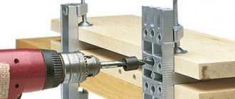
Using a drill as a machine tool
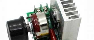
Figure 1. Typical diagram of a drill speed controller.
A hand drill can be used in non-standard ways. A variety of machines are made on its basis: drilling, grinding, circular and others. In such machines, the speed control function is very important. For most household drills, the speed is regulated by the device's start button. The harder it is pressed, the higher the speed. But they are fixed only at maximum values. In most cases this can be a significant drawback.
You can get out of this situation by making your own remote version of the speed controller. As a regulator, it is quite possible to use a dimmer, which is usually used to regulate lighting. The regulator circuit is quite simple and is shown in Fig. 1. To make it, you need to connect wires of different lengths to the socket. The other end of the long wire is connected to the plug. The rest is assembled according to the scheme. It is recommended to use an additional circuit breaker that will turn off the device in the event of an emergency.
The homemade speed controller is ready. You can perform a test run. If it works normally, you can place it in a suitable sized box and attach it to the frame of the future machine in a convenient place.
Return to contents