Often, when operating various equipment, it becomes necessary to control the speed of rotation of a DC electric motor. For this, special regulators or frequency converters are used. The simplest regulator can be made with your own hands.
During the operation of modern power tools and various equipment, it often becomes necessary to control the power and rotation speed of DC motors. To solve such problems, it is customary to use special regulators or frequency converters, which are now presented in a large variety on the electrical market. A correctly selected frequency converter allows you to smoothly reduce or increase the shaft speed and ensure long-term uninterrupted operation of the mechanisms.
To better understand the principle of operation of a DC motor speed controller, it is recommended to make it yourself. Even a person without deep knowledge and specialized skills in radio electronics can do this. To create a homemade device, you will definitely need a 12V or 24V regulator circuit that is optimally suited to the features and characteristics of your electric motor, operating from a regular 220-volt home power supply or intended for a three-phase network.
Areas of application and selection criteria for speed controller
Often, a rotation controller for electric motors is necessary for correct operation:
- industrial and household electric drives;
- electric welding machines;
- heating and air conditioning systems;
- electric furnaces;
- power supplies for computer equipment;
- voltage stabilizers;
- washing and sewing machines;
- vacuum cleaners and much more.
When choosing a DC motor speed controller, you need to pay attention to the features of the device and its recommended use:
- in commutator-type electric motors, vector regulators are more often used, but scalar ones are considered more reliable;
- the declared power of the controller must correspond to the rated characteristics of the power unit (even slightly exceed them to ensure more stable and safe operation of the system);
- voltage characteristics are selected within the permissible range;
- The rotation speed conversion parameters must meet the technical requirements of the equipment.
It is also important to take into account the overall dimensions, number of inputs/outputs, warranty period, etc.
Hardware interrupt
And then I realized what was going on: Arduino does not have time to process the readings of the Hall sensors! Therefore, it was necessary to use Arduino pins with hardware interrupt. Since Arduino UNO has only two such pins, and three pins are needed for sensors, you need to take Arduino Leonardo or Iskra Neo, where there are four such pins.
Having rewritten the program for interrupts and connecting Iskra Neo instead of UNO, I repeated the tests.
//H-bridge key pins const int TAH = 8; //T - transistor, A - phase (blue), H - upper switch of the half-bridge const int TAL = 9; //T - transistor, A - phase (blue), L - lower switch of the half-bridge const int TBH = 10; //T - transistor, B - phase (green), H - upper switch of the half-bridge const int TBL = 11; //T - transistor, B - phase (green), L - lower switch of the half-bridge const int TCH = 12; //T - transistor, C - phase (yellow), H - upper switch of the half-bridge const int TCL = 13; //T - transistor, C - phase (yellow), L - lower switch of the half-bridge //————————————————————————————— —— //hall sensors int HallA = 3; //pin 1 (with interruption) int HallB = 1; //pin 2 (with interruption) int HallC = 0; //pin 3 (with interruption) //————————————————————————————————— volatile boolean vala; volatile boolean valb; volatile boolean valc; //———————————————————————————————— void setup() { //Installing key pins to the output pinMode(TAH, OUTPUT); pinMode(TAL, OUTPUT); pinMode(TBH, OUTPUT); pinMode(TBL, OUTPUT); pinMode(TCH, OUTPUT); pinMode(TCL, OUTPUT); //Reading Hall sensors vala = digitalRead(HallA); valb = digitalRead(HallB); valc = digitalRead(HallC); //Hardware interrupt on Hall sensor pins attachInterrupt (digitalPinToInterrupt(HallA), changeA, CHANGE); attachInterrupt(digitalPinToInterrupt(HallB), changeB, CHANGE); attachInterrupt(digitalPinToInterrupt(HallC), changeC, CHANGE); //LOW causes an interrupt when the port is LOW //CHANGE interrupt is called when the value on the port changes from LOW to HIGH, and vice versa //RISING interrupt is called only when the value on the port changes from LOW to HIGH //FALLING interrupt is called only when there is a change values on the port from HIGH to LOW } void Phases() { digitalWrite(TAH, (vala && !valb) ? HIGH : LOW); digitalWrite(TAL, (valb && !vala) ? HIGH : LOW); digitalWrite(TBH, (valb && !valc) ? HIGH : LOW); digitalWrite(TBL, (valc && !valb) ? HIGH : LOW); digitalWrite(TCH, (valc && !vala) ? HIGH : LOW); digitalWrite(TCL, (vala && !valc) ? HIGH : LOW); void changeA() { vala = digitalRead(HallA); Faces(); } void changeB() { valb = digitalRead(HallB); Faces(); } void changeC() { valc = digitalRead(HallC); Faces(); } void loop() { }
The wheel finally worked smoothly, without vibrations or noise, and began to pick up speed perfectly without desynchronization. The prototype turned out to be viable. But this is not yet a full-fledged controller, since it did not have protections and a high-quality PWM signal.
Design features and operating principle of the frequency converter
Electronic frequency converters are used to control the operation of electric motors in both a three-phase 380V and single-phase 220V power supply. Their work is based on changing the amplitude and frequency of the electrical signal, which allows you to smoothly change the parameters of the rotor speed of the power unit. The design of most such devices, as a rule, is based on semiconductor-type transistors with pulse-width modulators. Speed adjustment is carried out using a control unit installed on the microcontroller.
Frequently used in power tools and household appliances, commutator-type DC motors are distinguished by the fact that when directly connected to a 220-volt power supply, they begin to produce maximum speed. This increases the load on the drive and contributes to its rapid wear. In addition, at high rotor speeds, a lot of heat is generated, which leads to overheating of the working mechanisms, melting of windings and cables, and can also cause a short circuit. Therefore, it is highly recommended to install a power and frequency regulator here, even if control over the speed in the technical process and operation of the electrical installation is not provided.
From the network
Single-phase AC motors also allow you to control the rotation of the rotor.
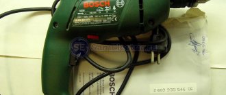
Collector machines
Such motors are found on electric drills, jigsaws and other tools.
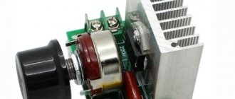
To reduce or increase the speed, it is enough, as in previous cases, to change the supply voltage. There are also solutions for this purpose. The structure connects directly to the network. The adjusting element is a triac, which is controlled by a dinistor. The triac is placed on the heat sink, the maximum load power is 600 W.
If there is a suitable LATR, you can do all this using it.
Two phase motor
The device, which has two windings - starting and working, is two-phase in principle. Unlike three-phase, it has the ability to change the rotor speed. The characteristic of its rotating magnetic field is not circular, but elliptical, which is due to its design.
There are two possibilities for controlling the speed:
- Change the amplitude of the supply voltage (Uy),
- Phase - change the capacitance of the capacitor.
Such units are widely used in everyday life and in production.
Regular asynchronous
Three-phase electric machines, despite their ease of operation, have a number of characteristics that need to be taken into account. If you simply change the supply voltage, the torque will change within a small range, but no more. In order to regulate speed within a wide range, you need quite complex equipment, which is difficult and expensive to simply assemble and set up.
For this purpose, the industry has launched the production of frequency converters that help change the speed of the electric motor in the desired range.
The asynchronous machine gains momentum in accordance with the parameters set on the frequency driver, which can be changed in a wide range. The converter is the best solution for such engines.
Using a homemade regulator
Previously, the most common type of engine governor was a mechanical one, which used a gear drive and a variator. But due to wear and tear of mechanical parts and the influence of external factors, they often failed and required repair. Electronic devices that allow you to increase the voltage smoothly or stepwise have proven themselves much better. In addition, they are distinguished by their compact size and the ability to more accurately adjust the operating parameters of the electrical installation.
Making a simple 12B DC motor controller with your own hands is not difficult, even if you have basic skills. To do this, it is enough to have the following components:
- switch for several positions;
- set of wirewound resistors;
- relay and control blocks.
With the help of resistors, the voltage from the power source changes, and therefore the speed of the electric motor. Such a homemade engine regulator accelerates it stepwise by setting the switch to the appropriate position. It can be effectively used to start asynchronous and contact type power units.
This device operates according to the following principle:
- voltage from the power source is applied to the capacitor, which is fully charged;
- the current is redirected to the outgoing wire and resistor;
- the thyristor electrode connected to the positive capacitor contact receives the load;
- after the voltage charge is transferred, the second semiconductor opens;
- the load coming from the capacitor is passed through the thyristor and the capacitor is discharged;
- the half-cycle cycle repeats.
If the regulator circuit additionally contains a triac or a device with a similar operating principle, then the change in voltage power proceeds smoothly. This means that the electric motor will pick up speed without jerking or noticeable vibrations, gradually reaching the required operating power. Also, to ensure better regulation, variable resistors can be included in the circuit.
How to make a current stabilizer for LEDs yourself
Making a stabilizer for LEDs with your own hands is carried out in several ways. It is advisable for a beginner to work with simple circuits.
Driver based
You will need to choose a chip that is difficult to burn out - LM317. It will act as a stabilizer. The second element is a variable resistor with a resistance of 0.5 kOhm with three terminals and an adjustment knob.
Assembly is carried out according to the following algorithm:
- Solder the conductors to the middle and extreme terminals of the resistor.
- Set the multimeter to resistance mode.
- Measure the parameters of the resistor - they should be equal to 500 Ohms.
- Check connections for integrity and assemble the circuit.
The output will be a module with a power of 1.5 A. To increase the current to 10 A, you can add a field switch.
Stabilizer for car lighting
Stabilizer L7812
To operate, you will need a linear device in the form of an L7812 microcircuit, two terminals, a 100n capacitor (1-2 pcs.), textolite material and a heat-shrinkable tube. Manufacturing is carried out step by step:
- Selecting a circuit for L7805 from the datasheet.
- Cut out the required size piece from the PCB.
- Mark the paths by making notches with a screwdriver.
- Solder the elements so that the input is on the left and the output is on the right.
- Make a housing from a thermal tube.
The stabilizing device can withstand up to 1.5 A load and is mounted on a radiator.
Speed controller on a PWM transistor
The process of adjusting the speed of a low-power electric motor can be organized using a PWM transistor and series-connected resistors from a power source. This method is quite easy to implement on your own, but it has a low efficiency and does not allow you to smoothly increase or decrease the rotor speed.
A homemade PWM speed controller using transistors has the following features:
- modern pulse-width modulation transistors contain a 150-Hz sawtooth voltage generator;
- operational amplifiers are used as a comparator;
- The duration of the pulses is controlled by a variable resistor, as a result of which the speed is adjusted.
The amplitude of the transistor pulses corresponds to the voltage amplitude of the power source. It is smooth and constant. Thanks to this property, adjustment of the electric motor speed is possible even when a minimum voltage is supplied to the transformer winding. Such a PWM speed controller allows you to connect a microcontroller to the transistor and thus automate the setup and adjustment of the operation of the electric drive. You can also include other components in the circuit that expand the functionality and automation capabilities of the electrical installation.
Scheme number 1
There was a stabilized switching power supply that gave an output voltage of 17 volts and a current of 500 milliamps. A periodic change in voltage was required in the range of 11 - 13 volts. And the well-known voltage regulator circuit on one transistor coped with this perfectly. I added only an indication LED and a limiting resistor to it. By the way, the LED here is not only a “firefly” signaling the presence of output voltage. With the correct value of the limiting resistor, even a small change in the output voltage is reflected in the brightness of the LED, which provides additional information about its increase or decrease. The output voltage could be changed from 1.3 to 16 volts.
KT829, a powerful low-frequency silicon compound transistor, was installed on a powerful metal radiator and it seemed that, if necessary, it could easily withstand a heavy load, but a short circuit occurred in the consumer circuit and it burned out. The transistor has a high gain and is used in low-frequency amplifiers - you can really see its place there and not in voltage regulators.
On the left are removed electronic components, on the right are prepared for replacement. The difference in quantity is two items, but in terms of the quality of the circuits, the former and the one that was decided to be collected, it is incomparable. This begs the question: “Is it worth assembling a scheme with limited capabilities when there is a more advanced option “for the same money”, in the literal and figurative sense of this saying?”
Thyristor control of electric motor speed
The thyristor regulator also allows you to change the speed of the power unit shaft. It is also called a dimmer or phase regulator. With this connection method, the electric motor is connected either to a break in the network cable, or behind a rectifier bridge that powers the anode thyristor circuit. This method of controlling the motor speed is considered quite reliable, provided that there are no violations of the integrity or order of contact connections in the load circuit. If you connect a commutator electric motor through a thyristor regulator, the brushes may begin to spark, since the load current will pulse.
Although, to control 12-volt DC motors of the collector type, you can adapt a thyristor regulator, which will have some features:
- the electric motor and power thyristor are connected to one of the diagonals of the rectifier bridge, and the voltage from the mains is supplied to the other diagonal;
- Thyristors are controlled not with short pulse signals, but with a wider range, which makes it possible to eliminate the detrimental effect on the operation of the regulator of short-term load drops characteristic of commutator electric motors.
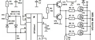
The generator of short, up to several milliseconds, positive pulses is assembled on a unijunction transistor VT1. It is designed to operate the auxiliary thyristor VS1. The trapezoidal supply voltage is supplied to the generator by limiting the 100-Hz positive half-waves of the sinusoidal voltage by the zener diode VD1. Each such half-wave gradually charges capacitor C1 through the resistive chain R1-R3.
When the voltage required to open the transistor appears on the capacitor, a positive pulse is applied from resistor R5 to the electrode of the control trinistor VS1, as a result of which this trinistor opens, and the power trinistor VS2 receives a pulse signal that is longer than the control signal and Electric motor M1 receives power.
The rotation speed of the electric motor rotor is adjusted using a variable resistor R1, which is responsible for the opening moment of the power and control thyristors, and therefore for the load power. The anode of the VS2 thyristor in its circuit has an inductive load, so spontaneous opening is possible even without receiving a control signal. To prevent this from happening, a diode VD is mounted, connected in parallel with the excitation winding LB.
The simplest option
The easiest way is to change the speed of a DC motor. They can be changed by simply changing the supply voltage. And it doesn’t matter where: at anchor or excited, but this only applies to low-power machines with minimal load. Basically, the rotation speed is controlled via the armature circuit. Moreover, rheostatic regulation is possible here if the motor power is small, or there is a fairly powerful rheostat.
This is the most uneconomical option. The mechanical characteristics of a motor with independent excitation are the most unfavorable due to large losses, which results in a drop in mechanical power and efficiency.
Another possibility is to introduce a rheostat into the field winding. Considering the characteristics of an engine with independent excitation, we will see that regulation of the rotation speed is possible only in the direction of increasing revolutions. This occurs due to winding saturation.
So, rheostat control of the rotation speed of an independent excitation apparatus is justified in systems with minimal load. It is best when the work with this switching on is periodic.
Introduction of automation
The presence of modern microcontroller control in speed controllers and frequency converters makes it possible to improve the operating parameters of the drive, and the motor itself can operate in a fully automatic mode, when the controller used smoothly or stepwise changes the rotation speed of the rotor of the power unit. Today, microcontroller control uses processors that have different numbers of outputs and inputs. You can connect various kinds of electronic keys and buttons, various signal loss sensors, etc. to such a microcontroller.
The modern electrical market offers a wide range of converters and frequency controllers for any type of electric motor. But if you have even minimal skills in working with radio components and the ability to read electrical circuits, you can assemble a device with your own hands that will gradually or stepwise change the engine speed. Additionally, you can include a control triac rheostat and a resistor in the circuit, which will make it possible to smoothly change the speed, and the presence of microcontroller control completely automates the operation of the electric drive.
Introduction.
Many years ago, I made a similar regulator when I had to earn extra money repairing radios at a customer’s home. The regulator turned out to be so convenient that over time I made another copy, since the first sample was constantly installed as an exhaust fan speed regulator. https://oldoctober.com/
By the way, this fan is from the Know How series, as it is equipped with an air shut-off valve of my own design. Description of the design >>> The material can be useful for residents living on the top floors of high-rise buildings and who have a good sense of smell.
The power of the connected load depends on the thyristor used and its cooling conditions. If a large thyristor or triac of the KU208G type is used, then you can safely connect a load of 200... 300 Watts. When using a small thyristor, type B169D, the power will be limited to 100 Watts.
Measurements
It is clear that the number of revolutions needs to be determined somehow. Tachometers are used for this. They show the rotation number at the moment. You can’t simply measure speed with a regular multimeter, except in a car.
As you can see, on electric machines you can change various parameters, adjusting them to the needs of production and household use.
DIY birthday decor
Close…
Pointed-toe cowboy bootsThe principle of operation of a homemade lock is as follows. In one half there is a permanent magnet. and in the other there is a metal plate. One of them is attached to the door. The second, with the metal plate removed, is equipped with a KEM-1 reed switch and attached to the door frame. If the door is in the closed position, the two parts of the lock are pressed, the magnet acts on the reed switch, closing its contacts. If the door opens, the magnet goes away and the reed switch contacts open.
The battery, the computer system unit, even the power supply for a laptop are all best friends. I’m already silent about such good hot water bottles as my husband and I.
Take the filler and stuff the doll. When the stuffing is completely evenly distributed, sew the product up. The handles must be sewn to the body almost near the neck.
From one pallet, sanded, impregnated and varnished, you get a garden table like a coffee table, on the left in Fig. If you have a pair in stock, you can make a wall-mounted work desk-rack out of them in literally half an hour, in the center and on the right. You can also weave chains for it yourself from soft wire, covered with a PVC tube or, better, heat-shrinkable. To fully raise the tabletop, small tools are placed on the shelf of a wall pallet.
Well, if you fill a glass bowl, vase, candy dish, punch vessel or ordinary glasses with water, scattering sea pebbles on the bottom, and let the candle-tablets float freely, you will get magical lighting for a romantic New Year. For a more interesting and unexpected effect, you can experiment with the color of the water. How are studs installed on rubber?
Handmade toys for children are beautiful, cheap and enjoyable. Every child needs original and educational toys, but it is not always possible to purchase them. Today we will show you 5 examples of fun toys that you can make yourself. They can be made from cardboard, paper or wood. In general, be inspired and make your children happy more often.
For the base of such a structure, you can use thick plywood, and for its upper part - polycarbonate. Finding solar panels online today is also not a problem.
Attention! When joining panels, do not use too much force, as you may damage the joint. This is exactly how many knives a housewife should have in her kitchen so that the cooking process is always simple and enjoyable.
This is exactly how many knives a housewife should have in her kitchen so that the cooking process is always simple and enjoyable.
To make a feeder with your own hands we will need:
Timber calculation. The boards, called staves, have biconvex sides to give the cooperage product a convexity. To make them like this, you need to take the lower part of a tree trunk and split it, similar to chopping wood. If you cut it carefully, the natural integrity of the fibers will be disrupted, which is bad for such a product. You shouldn’t start figure sawing right away - the logs need to be dried for 2 months. Moreover, dry it not under the scorching sun, but in a dark, cool room.
How to weave bracelets from laces
The fact that most New Year's costumes for preschool children are easily sewn on the basis of overalls can significantly narrow and facilitate creative search. If you learn how to sew a jumpsuit - the basis for a New Year's costume and come up with (draw from) and make decorative elements for it with your own hands, then you can make amazing and quite interesting models of New Year's outfits for children. The main thing is to think through everything in advance to the smallest detail, arm yourself with knowledge on the topic - so that the result of the work will pleasantly surprise and delight everyone.
Wardrobe design
Images
DIY birthday gift for mom photo instructions
Similar news
.
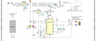
With the ever-increasing growth of automation in the domestic sector, there is a need for modern systems and devices for controlling electric motors.
Control and frequency conversion in small-power single-phase asynchronous motors, launched using capacitors, allows you to save energy and activates the energy saving mode at a new, progressive level.
Conclusion
As you can see, modern electrical engineering uses many effective control methods. All of them ensure smooth operation of engines, with a minimum of costs. Innovative technologies have also been implemented that allow you to control the motor via Wi-Fi. The selection of a specific method should be carried out based on the parameters of the unit and its technical capabilities. At the same time, the engine resource is not reduced, because each individual method takes into account all design features.
There are many variations of regulators on the market, each of which is created based on a specific method. Most often, PWM pulses are used, as well as all sorts of their combinations, for example with bridge circuits.
Motor control via H-bridge
The solutions that we have presented so far have a main drawback - with their help it is not possible to control the engine in two directions! This need will most likely come in handy, for example, in the construction of robots. An H-bridge is a design that can be built with both types of transistors and relays.
The "H" comes from the fact that the four relays and the motor in the middle form an "H" in the diagram.
You can read more about how the H-bridge works here
Step-by-step instruction
The classic sinistor circuit works on the principle of charging a capacitor through a low-capacitance resistor. After the voltage between the plates reaches the desired value, the triac begins to pass current to the load.
In this way, you can control the capacitance of the capacitor by changing the voltage that goes to the load. A rheostat, which is installed in place of the resistor, is perfect for this.
Unfortunately, such a circuit heats up quickly, which is why it is necessary to install an additional radiator to effectively remove heat.
This installation can operate from an internal storage device with a voltage of 12 V and an external one of 220 V. However, in this case, a quenching circuit is required.
In this operating mode, you can change the threshold power, this directly affects the power of the rotor. Power resistors are set to specific readings of the incoming current, collecting it in the required volumes.