To perform many types of work on wood, metal or other types of materials, it is not high speeds that are required, but good traction. It would be more correct to say - moment. It is thanks to him that the planned work can be completed efficiently and with minimal power losses. For this purpose, DC (or commutator) motors are used as a drive device, in which the supply voltage is rectified by the unit itself. Then, to achieve the required performance characteristics, it is necessary to adjust the speed of the commutator motor without loss of power.
Features of speed control
It is important to know that each motor, when rotating, consumes not only active, but also reactive power. In this case, the level of reactive power will be higher, which is due to the nature of the load. In this case, the task of designing devices for regulating the rotation speed of commutator motors is to reduce the difference between active and reactive powers. Therefore, such converters will be quite complex, and it is not easy to make them yourself.
You can construct only some semblance of a regulator with your own hands, but there is no point in talking about saving power. What is power? In electrical terms, it is the current drawn multiplied by the voltage. The result will give a certain value that includes active and reactive components. To isolate only the active one, that is, to reduce losses to zero, it is necessary to change the nature of the load to active. Only semiconductor resistors have these characteristics.
Therefore, it is necessary to replace the inductance with a resistor , but this is impossible, because the motor will turn into something else and obviously will not set anything in motion. The goal of lossless regulation is to maintain torque, not power: it will still change. Only a converter can cope with such a task, which will control the speed by changing the duration of the opening pulse of thyristors or power transistors.
How to make it yourself?
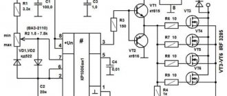
There are various options for adjustment schemes. Let us present one of them in more detail.
Here is how it works:
Initially, this device was developed to adjust the commutator motor in electric vehicles. We were talking about one where the supply voltage is 24 V, but this design is also applicable to other engines.
The weak point of the circuit, which was identified during testing of its operation, is its poor suitability at very high current values. This is due to some slowdown in the operation of the transistor elements of the circuit.
It is recommended that the current be no more than 70 A. There is no current or temperature protection in this circuit, so it is recommended to build in an ammeter and monitor the current visually. The switching frequency will be 5 kHz, it is determined by capacitor C2 with a capacity of 20 nf.
As the current changes, this frequency can change between 3 kHz and 5 kHz. Variable resistor R2 is used to regulate the current. When using an electric motor at home, it is recommended to use a standard type regulator.
At the same time, it is recommended to select the value of R1 in such a way as to correctly configure the operation of the regulator. From the output of the microcircuit, the control pulse goes to a push-pull amplifier using transistors KT815 and KT816, and then goes to the transistors.
The printed circuit board has a size of 50 by 50 mm and is made of single-sided fiberglass:
This diagram additionally shows 2 45 ohm resistors. This is done for the possible connection of a regular computer fan to cool the device. When using an electric motor as a load, it is necessary to block the circuit with a blocking (damper) diode, which in its characteristics corresponds to twice the load current and twice the supply voltage.
We recommend reading: LED garland on a 27c512 chip
Operating the device in the absence of such a diode may lead to failure due to possible overheating. In this case, the diode will need to be placed on the heat sink. To do this, you can use a metal plate that has an area of 30 cm2.
Regulating switches work in such a way that the power losses on them are quite small. In the original design, a standard computer fan was used. To connect it, a limiting resistance of 100 Ohms and a supply voltage of 24 V were used.
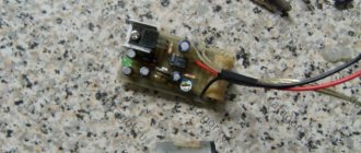
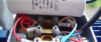
The assembled device looks like this:
When manufacturing a power unit (in the lower figure), the wires must be connected in such a way that there is a minimum of bending of those conductors through which large currents pass. We see that the manufacture of such a device requires certain professional knowledge and skills. Perhaps in some cases it makes sense to use a purchased device.
Generalized controller circuit
An example of a controller that implements the principle of controlling a motor without power loss is a thyristor converter. These are proportional-integral circuits with feedback, which provide strict control of characteristics, ranging from acceleration-braking to reverse. The most effective is pulse-phase control: the repetition rate of the unlocking pulses is synchronized with the network frequency. This allows you to maintain torque without increasing losses in the reactive component. The generalized diagram can be represented in several blocks:
- power controlled rectifier;
- rectifier control unit or pulse-phase control circuit;
- tachogenerator feedback;
- current control unit in the motor windings.
Before delving into a more precise device and principle of regulation, it is necessary to decide on the type of commutator motor. The control scheme for its performance characteristics will depend on this.
Types of commutator motors
At least two types of commutator motors are known. The first includes devices with an armature and an excitation winding on the stator. The second includes devices with an armature and permanent magnets. It is also necessary to decide for what purposes the regulator needs to be designed:
- If it is necessary to regulate with a simple movement (for example, by rotating a grinding stone or drilling), then the speed will need to be changed within the range from some minimum value, not equal to zero, to the maximum. Approximate value: from 1000 to 3000 rpm. A simplified circuit with 1 thyristor or a pair of transistors is suitable for this.
- If it is necessary to control the speed from 0 to maximum, then you will have to use full-fledged converter circuits with feedback and strict control characteristics. Usually, self-taught craftsmen or amateurs end up with commutator motors with an excitation winding and a tachogenerator. Such a motor is a unit used in any modern washing machine and often fails. Therefore, let’s consider the principle of controlling this particular engine, studying its structure in more detail.
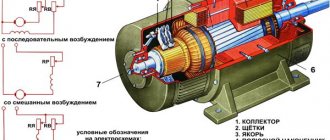
Motor design
Structurally, the engine from the Indesit washing machine is simple, but when designing a controller to control its speed, it is necessary to take into account the parameters. Motors may have different characteristics, which is why the control will also change. The operating mode is also taken into account, which will determine the design of the converter. Structurally, the commutator motor consists of the following components:
- An armature, it has a winding laid in the grooves of the core.
- Collector, a mechanical rectifier of alternating mains voltage, through which it is transmitted to the winding.
- Stator with field winding. It is necessary to create a constant magnetic field in which the armature will rotate.
When the current in the motor circuit, connected according to the standard circuit, increases, the field winding is connected in series with the armature. With this inclusion, we also increase the magnetic field acting on the armature, which allows us to achieve linearity of characteristics. If the field remains unchanged, then it will be more difficult to obtain good dynamics, not to mention large power losses. It is better to use such motors at low speeds, since they are more convenient to control at small discrete movements.
By organizing separate control of the excitation and armature, it is possible to achieve high positioning accuracy of the motor shaft, but the control circuit will then become significantly more complicated. Therefore, we will take a closer look at the controller, which allows you to change the rotation speed from 0 to the maximum value, but without positioning. This may be useful if a full-fledged drilling machine with the ability to cut threads will be made from the engine from a washing machine.
What are they needed for
Many household appliances and power tools cannot do without a commutator motor.
The popularity of this electric motor is due to its versatility. For a commutator electric motor, power supply from direct or alternating voltage current can be used. An additional benefit is the efficient starting torque. At the same time, operation from direct or alternating current of the electric motor is accompanied by a high rotation frequency, which is not suitable for all users. To ensure a smoother start and the ability to adjust the rotation speed, a speed controller is used. A simple regulator can be made with your own hands.
But before the circuit is discussed, we first need to understand brushed motors.
Commutator motors
The design of any commutator motor includes several basic elements:
The operation of a standard commutator motor is based on the following principles.
- Current is supplied from a 220V voltage source. 220 Volts is the standard household voltage. Most appliances with electric motors do not require more than 220 volts. Moreover, the current is supplied to the rotor and stator, which are connected to one another.
- As a result of the supply of current from a 220V source, a magnetic field is formed.
- Under the influence of magnetic voltage, the rotor begins to rotate.
- The brushes transmit voltage directly to the rotor of the device. Moreover, brushes are usually made on the basis of graphite.
- When the direction of current in the rotor or stator changes, the shaft rotates in the opposite direction.
In addition to standard commutator motors, there are other units:
- Series excitation electric motor. Their resistance to overloads is more impressive. Often found in household electrical appliances,
- Parallel excitation devices. Their resistance is not high, the number of turns is significantly greater than that of their analogues,
- Single-phase electric motor. It is very easy to make with your own hands, the power is at a decent level, but the efficiency leaves much to be desired.
Scheme selection
Having found out all the conditions under which the motor will be used, you can begin to manufacture a speed controller for the commutator motor. You should start by choosing a suitable scheme that will provide you with all the necessary characteristics and capabilities. You should remember them:
- Speed regulation from 0 to maximum.
- Providing good torque at low speeds.
- Smooth speed control.
Looking at many schemes on the Internet, we can conclude that few people are creating such “units”. This is due to the complexity of the control principle, since it is necessary to organize the regulation of many parameters. Thyristor opening angle, control pulse duration, acceleration-deceleration time, torque rise rate. These functions are handled by a circuit on the controller that performs complex integral calculations and transformations. Let's consider one of the schemes, which is popular among self-taught craftsmen or those who simply want to put to good use an old motor from a washing machine.
All our criteria are met by a circuit for controlling the rotation speed of a brushed motor, assembled on a specialized TDA 1085 microcircuit. This is a completely ready-made driver for controlling motors that allow you to adjust the speed from 0 to the maximum value, ensuring torque maintenance through the use of a tachogenerator.
Design Features
The microcircuit is equipped with everything necessary for high-quality engine control in various speed modes, from braking to acceleration and rotation at maximum speed. Therefore, its use greatly simplifies the design, while simultaneously making the entire drive universal , since you can select any speed with a constant torque on the shaft and use it not only as a drive for a conveyor belt or drilling machine, but also for moving a table.
The characteristics of the microcircuit can be found on the official website. We will indicate the main features that will be required to construct the converter. These include: an integrated frequency-to-voltage conversion circuit, an acceleration generator, a soft starter, a Tacho signal processing unit, a current limiting module, etc. As you can see, the circuit is equipped with a number of protections that will ensure stable operation of the regulator in different modes.
The figure below shows a typical circuit diagram for connecting a microcircuit.
The scheme is simple, so it is quite reproducible with your own hands. There are some features that include limit values and speed control method:
- The maximum current in the motor windings should not exceed 10 A (subject to the configuration shown in the diagram). If you use a triac with a large forward current, the power can be higher. Please note that you will need to change the resistance in the feedback circuit downward, as well as the inductance of the shunt.
- The maximum rotation speed is 3200 rpm. This characteristic depends on the type of engine. The circuit can control motors up to 16 thousand rpm.
- Acceleration time to maximum speed reaches 1 second.
- Normal acceleration is achieved in 10 seconds from 800 to 1300 rpm.
- The engine uses an 8-pole tachogenerator with a maximum output voltage of 30 V at 6000 rpm. That is, it should produce 8 mV per 1 rpm. At 15,000 rpm it should show 12 V.
- To control the motor, a 15A triac with a maximum voltage of 600 V is used.
If you need to organize a motor reverse, then for this you will have to supplement the circuit with a starter that will switch the direction of the excitation winding. You will also need a zero speed control circuit to give permission for reverse. Not shown in the picture.
RN on 2 transistors
This type is used in circuits of particularly powerful regulators. In this case, the current to the load is also transmitted through a triac, but the key terminal is controlled through a cascade of transistors. This is implemented like this: a variable resistor regulates the current that goes to the base of the first low-power transistor, which, through the collector-emitter junction, controls the base of the second high-power transistor and it opens and closes the triac. This implements the principle of very smooth control of huge load currents.
SNiP 3.05.06-85
Answers to the 4 most frequently asked questions regarding regulators:
- What is the permissible deviation of the output voltage? For factory instruments of large companies, the deviation will not exceed + -5%
- What does the regulator power depend on? The output power directly depends on the power source and on the triac that switches the circuit.
- What are 0-5 volt regulators for? These devices are most often used to power microcircuits and various circuit boards.
- Why do you need a 0-220 volt household regulator? They are used for smooth switching on and off of household electrical appliances.
Control principle
When the rotation speed of the motor shaft is set by a resistor in output circuit 5, a sequence of pulses is formed at the output to unlock the triac by a certain angle. The speed of rotation is monitored by a tachogenerator, which occurs in digital format. The driver converts the received pulses into an analog voltage, which is why the shaft speed is stabilized at a single value, regardless of the load. If the voltage from the tachogenerator changes, the internal regulator will increase the level of the output control signal of the triac, which will lead to an increase in speed.
The microcircuit can control two linear accelerations, allowing you to achieve the dynamics required from the engine. One of them is installed on the Ramp 6 output circuit . This regulator is used by washing machine manufacturers themselves, so it has all the advantages to be used for domestic purposes. This is ensured by the presence of the following blocks:
- Voltage stabilizer to ensure normal operation of the control circuit. It is implemented at pins 9, 10.
- Rotation speed control circuit. Implemented using MS pins 4, 11, 12. If necessary, the controller can be switched to an analog sensor, then pins 8 and 12 are combined.
- Starting impulse block. It is implemented at pins 1, 2, 13, 14, 15. It adjusts the duration of control pulses, delays, generates them from a constant voltage and calibrates.
- Sawtooth voltage generation device. Pins 5, 6 and 7. It is used to control the speed according to the set value.
- Control amplifier circuit. Pin 16. Allows you to adjust the difference between the set and actual speed.
- Current limiting device at pin 3. When the voltage on it increases, the triggering angle of the triac decreases.
The use of such a circuit ensures full control of the commutator motor in any mode. Thanks to forced acceleration control, it is possible to achieve the required acceleration speed to a given rotation speed. Such a regulator can be used for all modern washing machine motors used for other purposes.
Reasons and applications of PWM
The principle of pulse width modulation is used in speed controllers of powerful asynchronous motors. In this case, a modulating signal of adjustable frequency (single-phase or three-phase) is generated by a low-power sine wave generator and superimposed on the carrier in an analogue way. The output produces a PWM signal, which is supplied to the switches of the required power. Then you can pass the resulting sequence of pulses through a low-pass filter, for example through a simple RC chain, and isolate the original sinusoid. Or you can do without it - filtration will occur naturally due to the inertia of the engine. Obviously, the higher the carrier frequency, the closer the output waveform is to the original sine wave.
We recommend reading: Transistors of the KT315 and KT 361 series
A natural question arises: why can’t the generator signal be amplified immediately, for example, by using powerful transistors? Because the regulating element operating in linear mode will redistribute power between the load and the switch. In this case, significant power is wasted on the key element. If a powerful control element operates in switching mode (thyristor, triac, RGBT transistor), then the power is distributed over time. Losses will be much lower, and efficiency will be much higher.
In digital technology there is no special alternative to pulse width control. The amplitude of the signal there is constant; the voltage and current can only be changed by modulating the carrier along the pulse width and subsequently averaging it. Therefore, PWM is used to regulate voltage and current on those objects that can average a pulse signal. Averaging occurs in different ways:
- Due to load inertia. Thus, the thermal inertia of thermoelectric heaters and incandescent lamps allows the controlled objects not to noticeably cool down in pauses between pulses.
- Due to the inertia of perception. The LED manages to go out from pulse to pulse, but the human eye does not notice this and perceives it as a constant glow with varying intensities. This principle is used to control the brightness of LED monitors. But imperceptible blinking with a frequency of several hundred hertz is still present and causes eye fatigue.
- Due to mechanical inertia. This property is used when controlling brushed DC motors. If the control frequency is correctly selected, the motor does not have time to slow down during dead pauses.
Therefore, PWM is used where the average value of voltage or current plays a decisive role. In addition to the common cases mentioned, the PWM method is used to regulate the average current in welding machines and battery chargers, etc.
If natural averaging is not possible, in many cases this role can be taken over by the already mentioned low-pass filter (LPF) in the form of an RC chain. For practical purposes, this is enough, but you need to understand that it is impossible to isolate the original signal from PWM using a low-pass filter without distortion. After all, the PWM spectrum contains an infinitely large number of harmonics, which will inevitably fall into the filter passband. Therefore, you should not create illusions about the shape of the reconstructed sinusoid.
PWM control of an RGB LED is very effective and efficient. This device has three pn junctions - red, blue, green. By changing the brightness of each channel separately, you can get almost any LED color (with the exception of pure white). The possibilities for creating lighting effects using PWM are endless.
The most common application of a pulse-width modulated digital signal is to regulate the average current or voltage flowing through a load. But non-standard use of this type of modulation is also possible. It all depends on the imagination of the developer.