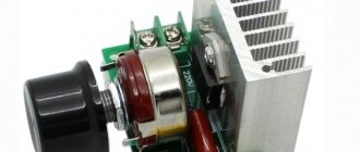
Often, when operating various equipment, it becomes necessary to control the speed of rotation of a DC electric motor. For this, special regulators or frequency converters are used. The simplest regulator can be made with your own hands.
During the operation of modern power tools and various equipment, it often becomes necessary to control the power and rotation speed of DC motors. To solve such problems, it is customary to use special regulators or frequency converters, which are now presented in a large variety on the electrical market. A correctly selected frequency converter allows you to smoothly reduce or increase the shaft speed and ensure long-term uninterrupted operation of the mechanisms.
To better understand the principle of operation of a DC motor speed controller, it is recommended to make it yourself. Even a person without deep knowledge and specialized skills in radio electronics can do this. To create a homemade device, you will definitely need a 12V or 24V regulator circuit that is optimally suited to the features and characteristics of your electric motor, operating from a regular 220-volt home power supply or intended for a three-phase network.
Types of engines
The speed control with power maintenance is an invention that will breathe new life into an electrical appliance, and it will work like a newly purchased product . But it is worth remembering that engines come in different formats and each has its own maximum performance.
The engines have different characteristics. This means that this or that technique operates at different speeds of the shaft that triggers the mechanism. The motor can be :
Mostly three-phase electric motors are found in factories or large factories. At home, single-phase and two-phase are used. This electricity is enough to operate household appliances.
Back-to-back, parallel, series connection of zener diodes
To increase the stabilization voltage, two or more zener diodes can be connected in series. For example, you need to get 17 V at the load, then, if the required rating is not available, support diodes of 5.1 V and 12 V are used.
Parallel connection is used to increase current and power.
Zener diodes are also used to stabilize alternating voltage. In this case, they are connected in series and counter.
During one half-cycle of alternating voltage, one zener diode operates, and the second operates like a regular diode. In the second half-cycle, semiconductor elements perform opposite functions. However, in this case, the shape of the output voltage will be different from the input voltage and will look like a trapezoid. Due to the fact that the reference diode will cut off a voltage exceeding the stabilization level, the tops of the sine wave will be cut off.
Power speed regulator
Work principles
A 220 V electric motor speed controller without loss of power is used to maintain the initial set shaft speed. This is one of the basic principles of this device, which is called a frequency regulator.
With its help, the electrical device operates at the set engine speed and does not reduce it . The engine speed controller also affects the cooling and ventilation of the motor. With the help of power, the speed is set, which can be either raised or reduced.
Many people have asked the question of how to reduce the speed of a 220 V electric motor. But this procedure is quite simple. One has only to change the frequency of the supply voltage, which will significantly reduce the performance of the motor shaft. You can also change the power supply to the motor by activating its coils. Electrical control is closely related to the magnetic field and motor slip. For such actions, they mainly use an autotransformer and household regulators, which reduce the speed of this mechanism. But it is also worth remembering that engine power will decrease.
Shaft rotation
Engines are divided into:
The speed controller of an asynchronous electric motor depends on the current connection to the mechanism. The essence of the operation of an asynchronous motor depends on the magnetic coils through which the frame passes. It rotates on sliding contacts. And when, when turning, it turns 180 degrees, then through these contacts the connection will flow in the opposite direction. This way the rotation will remain the same. But with this action the desired effect will not be obtained. It will come into force after a couple of dozen frames of this type are added to the mechanism.
The commutator motor is used very often . Its operation is simple, since the transmitted current passes directly - because of this, the power of the electric motor is not lost, and the mechanism consumes less electricity.
The washing machine motor also needs power adjustment. For this purpose, special boards were made that cope with their job: the engine speed control board from a washing machine has multifunctional use, since its use reduces the voltage, but does not lose rotation power.
The circuit of this board has been verified. All you have to do is install diode bridges and select an optocoupler for the LED. In this case, you still need to put a triac on the radiator. Basically, engine adjustment starts at 1000 rpm.
If you are not satisfied with the power regulator and its functionality is lacking, you can make or improve the mechanism . To do this, you need to take into account the current strength, which should not exceed 70 A, and heat transfer during use. Therefore, an ammeter can be installed to adjust the circuit. The frequency will be small and will be determined by capacitor C2.
Next, you should configure the regulator and its frequency. When outputting, this pulse will go out through a push-pull amplifier using transistors. You can also make 2 resistors that will serve as an output for the computer's cooling system. To prevent the circuit from burning out, a special blocker is required, which will serve as double the current value. So this mechanism will work for a long time and in the required volume. Power regulating devices will provide your electrical appliances with many years of service without special costs.
When starting the electric motor, the current consumption exceeds 7 times, which contributes to premature failure of the electrical and mechanical parts of the motor. To prevent this, you should use an electric motor speed controller. There are many factory-made models, but in order to make such a device yourself, you need to know the principle of operation of the electric motor and how to regulate rotor speed.
The principle of operation of a zener diode
Let's consider the principle of operation of a zener diode using the example of its connection circuit and current-voltage characteristic. To perform its main function, the zener diode VD is connected in series with a resistor Rb and together they are connected to a source of unstabilized input voltage Uin. The already stabilized output voltage Uout is removed only from pins 2, 3 VD. Therefore, the load Rн is connected to the corresponding points 2 and 3. As can be seen from the diagram, VD and Rb form a voltage divider. Only the resistance of the zener diode does not have a constant value and is called dynamic, since it depends on the amount of electric current flowing through the semiconductor device.
The voltage Uin supplied to the zener diode from the resistors must be at least a couple of volts higher than the output voltage Uout, otherwise the semiconductor device VD will not open and will not be able to perform its main function.
Let's say that at some arbitrary point in time at outputs 1 and 3 the value of Uin began to increase. The following processes will begin to occur in the circuit. As the voltage increases, according to Ohm's law, the current will begin to increase, let's call it the input current Iin. As the current increases, the voltage drop across the resistor Rb will increase, and at VD it will remain unchanged (this will be explained further in the characteristic), therefore Uout will remain at the same level. Consequently, the increase in input voltage will drop or be extinguished by resistor Rb. Therefore, Rb is called damping or ballast.
Now, let’s say the load has changed, for example, the resistance Rн has decreased, and the current In will increase accordingly. In this case, the current flowing through the zener diode Ist will decrease, and Iin will remain virtually unchanged.
General information
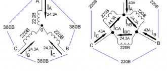
AC electric motors have become widespread in many areas of human activity, namely asynchronous-type models. The main purpose of the engine as an electric machine is the transformation of electrical energy into mechanical energy . Asynchronous in translation means non-simultaneous, since the rotor speed differs from the frequency of the alternating voltage (U) in the stator. There are two types of asynchronous motors based on the type of power supply:
Single-phase ones are used for household needs, and three-phase ones are used in production. Three-phase asynchronous motors (hereinafter referred to as TAM) use two types of rotors:
- closed;
- phase
Closed-circuit motors make up about 95% of all motors used and have significant power (from 250 W and above). The phase type is structurally different from AD , but is used quite rarely compared to the first. The rotor is a cylindrical steel figure that is placed inside the stator, with a core pressed onto its surface.
Squirrel cage and wound rotors
Highly conductive copper (for high-power machines) or aluminum rods (for lower-power machines) soldered or poured into the surface of the core and short-circuited at the ends with two rings play the role of electromagnets with poles facing the stator. The winding rods do not have any insulation, since the voltage in such a winding is zero.
More commonly used for mid-power motor cores, aluminum has low density and high electrical conductivity.
Read also: How is cross-sectional area denoted in physics
To reduce the higher harmonics of the electromotive force (EMF) and eliminate the pulsation of the magnetic field, the rotor rods have a specifically calculated angle of inclination relative to the axis of rotation. If a low-power electric motor is used, the grooves are closed structures that separate the rotor from the gap in order to increase the inductive component of the resistance.
The rotor in the form of a phase design or type is characterized by a winding, its ends are connected in a star type and attached to slip rings (on the shaft), along which graphite brushes slide. To eliminate eddy currents, the surface of the windings is covered with an oxide film. In addition, a resistor is added to the rotor winding circuit, which allows you to change the active resistance (R) of the rotor circuit to reduce the values of inrush currents (Ip). Starting currents negatively affect the electrical and mechanical parts of the electric motor. Variable resistors used to regulate Ip:
- Metal or stepped with manual switching.
- Liquid (due to immersion to the depth of the electrodes).
Graphite brushes are subject to wear, and some models are equipped with a squirrel-cage design that lifts the brushes and closes the rings after the motor starts. IMs with a wound rotor are more flexible in terms of regulation of Ip.
Design features
An asynchronous motor does not have pronounced poles, unlike a DC electric motor. The number of poles is determined by the number of coils in the windings of the stationary part (stator) and the method of connection. In an asynchronous machine with 4 coils, a magnetic flux passes through. The stator is made of special steel sheets (electrical steel), which reduce eddy currents to zero, at which significant heating of the windings occurs. It leads to a massive interturn short circuit.
The iron ore or rotor core is pressed directly onto the shaft. There is a minimum air gap between the rotor and stator. The rotor winding is made in the form of a “squirrel cage” and is made of copper or aluminum rods.
In electric motors with a power of up to 100 kW, aluminum, which has a low density, is used to fill the grooves of the rotor core. But despite this device, engines of this type get hot. To solve this problem, fans are used for forced cooling , which are mounted on the shaft. These engines are simple and reliable. However, motors consume a large current when starting, 7 times the rated current. Because of this, they have a low starting torque, since most of the electrical energy goes to heating the windings.
Electric motors, which have an increased starting torque, differ from ordinary asynchronous motors in the design of the rotor. The rotor is made in the form of a double “squirrel cage”. These models are similar to the phase types of rotor manufacturing. It consists of an inner and outer “squirrel cage”, and the outer one is the starting one and has a large active and small reactive R. The outer one has a slight active and high reactive R. As the rotation speed increases, I switches to the inner cage and operates in the form of a squirrel-cage rotor.
Principle of operation
When I flows through the stator winding, a magnetic flux (F) is created in each of them. These F are shifted by 120 degrees relative to each other. The resulting F is rotating, creating an electromotive force (EMF) in aluminum or copper conductors. As a result of this, a starting magnetic moment of the electric motor is created, and the rotor begins to rotate. This process is also called slip (S) in some sources, showing the frequency difference n1 of the electromagnetic field of the starter, which becomes greater than the frequency obtained when rotor n2 rotates. It is calculated as a percentage and has the form: S = ((n1-n2)/n1) * 100%.
The value of S at the initial start of the electric motor is approximately 1, but as the values increase, n2 becomes smaller. At this moment, I in the rotor decreases, therefore, the EMF becomes less than its nominal value. At idle, S is minimal, but as the moment of static interaction between the rotor and stator increases, this value reaches a critical value. If the inequality is satisfied: S > Scr, then the motor operates normally, but if the value of Scr is exceeded, it may “capsize”. Rollover causes unstable operation but disappears over time.
Marking of zener diodes
Markings are applied to the zener diode housing in the form of numbers and letters (or letters). There are fundamentally two different types of markings. The zener diode in a glass case has the usual markings for us, directly indicating the rated stabilization voltage. The numbers can be separated by the letter V, which acts as a decimal point. For example, 5V1 means 5.1 V.
A less clear way of marking consists of four numbers and a letter at the end. If you are not an experienced radio amateur, then you can’t do without a datasheet. For example, let's decipher the parameters of the reference diode of the 1N5349B series. We are most interested in the first column, which shows the rated voltage of 12 V. The second column is the rated current value - 100 mA.
The cathode of a zener diode of any type is indicated by a black or blue ring, which is applied to the body from the side of the corresponding terminal.
Speed setting methods
To prevent negative influence during start-up, you need to reduce the speed of the electric motor 220 V or 380 V. There are several ways to achieve this goal:
- Changing the R value of the rotor circuit.
- Change in U in the stator winding.
- Change of frequency U.
- Switching poles.
When changing the R value of the rotor part using additional resistors, the rotation speed decreases, but as a result, the power decreases. Consequently, there is a significant loss of electricity. This type of regulation should be used for a wound rotor.
By changing the U values on the stator coil, mechanical or electrical control of the rotor speed is possible. In this case, the U regulator is used. Using this method allows it to be used only with a fan load (for example, a 220V fan speed regulator). For all other cases, three-phase automatic transformers are used, which allow smooth changes in U values, or thyristor regulators.
Based on the formula for the dependence of the rotation speed on the supply frequency U, it is possible to regulate the number of rotor revolutions. The frequency of the rotating magnetic field of the stator is calculated by the formula: Nst = 60 * f / p (f is the frequency of the supply network current, p is the number of pole pairs). This method provides the ability to smoothly control the rotation speed of the rotor part. To obtain a high efficiency, you need to change the frequency and U. This method is optimal for engines with a squirrel-cage rotor, since power losses are minimal. There are two methods for changing the number of pole pairs:
- In the stator (in the slots) you need to place 2 windings with different numbers p.
- The winding consists of two parts connected in parallel or in series.
Read also: Calculation of pipe bending strength calculator
The main disadvantage of this method is maintaining a stepwise change in the frequency of an electric motor with a squirrel-cage rotor.
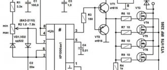
PSU circuit with current and voltage adjustments
Schematic diagram
| R1 = 2.2 KOhm 1W |
| R2 = 82 Ohm 1/4W |
| R3 = 220 Ohm 1/4W |
| R4 = 4.7 KOhm 1/4W |
| R5, R6, R13, R20, R21 = 10 KOhm 1/4W |
| R7 = 0.47 Ohm 5W |
| R8, R11 = 27 KOhm 1/4W |
| R9, R19 = 2.2 KOhm 1/4W |
| R10 = 270 KOhm 1/4W |
| R12, R18 = 56KOhm 1/4W |
| R14 = 1.5 KOhm 1/4W |
| R15, R16 = 1 KOhm 1/4W |
| R17 = 33 Ohm 1/4W |
| R22 = 3.9 KOhm 1/4W |
| RV1 = 100K trimmer |
| P1, P2 = 10KOhm linear pontesiometer |
| C1 = 3300 uF/50V electrolytic |
| C2, C3 = 47uF/50V electrolytic |
| C4 = 100nF polyester |
| C5 = 200nF polyester |
| C6 = 100pF ceramic |
| C7 = 10uF/50V electrolytic |
| C8 = 330pF ceramic |
| C9 = 100pF ceramic |
| D1, D2, D3, D4 = 1N5402,3,4 diode 2A – RAX GI837U |
| D5, D6 = 1N4148 |
| D7, D8 = 5.6V Zener |
| D9, D10 = 1N4148 |
| D11 = 1N4001 diode 1A |
| Q1 = BC548, NPN transistor or BC547 |
| Q2 = 2N2219 NPN transistor |
| Q3 = BC557, PNP transistor or BC327 |
| Q4 = 2N3055 NPN power transistor |
| U1, U2, U3 = TL081, operational amplifier |
| D12 = LED diode |
Here is another version of this scheme:
Types and selection criteria
To select a regulator, you need to be guided by certain characteristics for a particular case. Among all the criteria, you can choose the following:
- By type of control. For commutator-type motors, regulators with a vector or scalar control system are used.
- Power is the main parameter from which you need to build.
- By U band.
- By frequency range. You need to choose a model that meets the user's requirements for a particular case.
- Other characteristics, which include warranty, dimensions, equipment.
In addition, the regulator is selected more powerful than the electric motor itself according to the formula: Preg = 1.3 * Pmot (Preg, Pmot is the power of the regulator and the motor, respectively). It must be selected for different U ranges, since versatility plays an important role.
Thyristor device
This model, shown in Diagram 1, uses 2 thyristors connected back-to-back, although they can be replaced with one triac.
Scheme 1 - Thyristor speed control of a commutator motor without loss of power.
This circuit performs regulation by opening or closing thyristors (triacs) during a phase transition through the neutral. To correctly control a commutator motor, the following methods of modifying circuit 1 are used:
- Installation of LRC protective circuits consisting of capacitors, resistors and chokes.
- Adding capacitance at the input.
- The use of thyristors or triacs, the current of which exceeds the rated value of the motor current in the range of 3..8 times.
This type of regulator has advantages and disadvantages. The first include low cost, low weight and dimensions. The second ones include the following:
- application for low power motors;
- there is noise and jerking of the motor;
- when using a circuit based on triacs, a constant U hits the motor.
This type of regulator is installed in fans, air conditioners, washing machines and electric drills. Performs its functions perfectly, despite its shortcomings.
Transistor type
Another name for a transistor-type regulator is an autotransformer or PWM regulator (scheme 2). It changes the value of U according to the principle of pulse width modulation (PWM) using an output stage that uses IGBT transistors.
Scheme 2 - Transistor PWM speed controller.
Switching of transistors occurs at a high frequency and thanks to this it is possible to change the width of the pulses. Consequently, the value of U will also change. The longer the pulse and the shorter the pause, the higher the value of U and vice versa. The positive aspects of using this variety are as follows:
- Low weight of the device with small dimensions.
- Quite low cost.
- At low speeds there is no noise.
- Control via low U values (0..12 V).
The main disadvantage of the application is that the distance to the electric motor should be no more than 4 meters.
Frequency regulation
Regulating the speed of motors of various types due to frequency is widely used. Frequency conversion occupies a leading position in the market for sales of speed control devices and soft starting. Thanks to its versatility, it is possible to influence the power, performance and speed of any device with an electric motor. These devices are used for single-phase and three-phase motors. The following types of frequency converters are used:
- Specialized single-phase.
- Three-phase without capacitor.
To regulate the speed, a capacitor is used, connected to the windings of a single-phase motor (diagram 3). This frequency converter (FC) has a capacitive R, which depends on the frequency of the flowing alternating current. The output stage of such an inverter is made of IGBT transistors.
Scheme 3 - Frequency speed controller.
A specialized inverter has its advantages and disadvantages. The advantages are the following:
- Blood pressure control without human intervention.
- Stability.
- Additional features.
It is possible to control the operation of the electric motor under certain conditions, as well as protection against overloads and short-circuit currents. In addition, it is possible to expand the functionality by connecting digital sensors, monitoring operating parameters and using a PID controller. The disadvantages include limitations in frequency control and a fairly high cost.
For three-phase IM, frequency control devices are also used (Scheme 4). The regulator has three phases at the output for connecting an electric motor.
Scheme 4 - inverter for a three-phase motor.
This option also has its strengths and weaknesses. The first include the following: low cost, choice of power, wide range of frequency regulation, as well as all the advantages of single-phase frequency converters. Among all the negative aspects, the main ones can be identified: preliminary selection and heating during startup.
Selecting a device
In order to select an effective regulator, it is necessary to take into account the characteristics of the device and its intended purpose.
- Vector controllers are common for commutator motors, but scalar controllers are more reliable.
- An important selection criterion is power. It must correspond to that permitted on the unit used. It is better to exceed for safe operation of the system.
- The voltage must be within acceptable wide ranges.
- The main purpose of the regulator is to convert frequency, so this aspect must be selected according to the technical requirements.
- You also need to pay attention to the service life, dimensions, number of inputs.
Triac device
The triac device is used to control lighting, power of heating elements, and rotation speed.
The controller circuit based on a triac contains a minimum of parts shown in the figure, where C1 is a capacitor, R1 is the first resistor, R2 is the second resistor.
Using a converter, power is regulated by changing the time of an open triac. If it is closed, the capacitor is charged by the load and resistors. One resistor controls the amount of current, and the second regulates the charging rate.
When the capacitor reaches the maximum voltage threshold of 12V or 24V, the switch is activated. The triac goes into the open state. When the mains voltage passes through zero, the triac is locked, and then the capacitor gives a negative charge.
DIY making
If there is no opportunity or desire to purchase a factory-type regulator, then you can assemble it yourself. Although regulators of the "tda1085" type have proven themselves very well. To do this, you need to familiarize yourself with the theory in detail and start practicing. Triac circuits are very popular, in particular the speed controller of a 220V asynchronous motor (diagram 5). It's not difficult to make. It is assembled using a VT138 triac, which is well suited for these purposes.
Scheme 5 - Simple speed controller on a triac.
This regulator can also be used to adjust the speed of a 12-volt DC motor, as it is quite simple and universal. The speed is regulated by changing the parameters P1, which determines the phase of the incoming signal, which opens the transition of the triac.
The operating principle is simple. When the engine starts, it slows down, the inductance changes downward and contributes to an increase in U in the “R2—>P1—>C2” circuit. When C2 is discharged, the triac opens for some time.
There is another scheme. It works a little differently: by providing a reverse type of energy flow, which is optimally beneficial. The circuit includes a fairly powerful thyristor.
Scheme 6 - Design of a thyristor regulator.
The circuit consists of a control signal generator, an amplifier, a thyristor and a circuit section that functions as a rotor rotation stabilizer.
The most universal circuit is a regulator based on a triac and dinistor (scheme 7). It is able to smoothly reduce the shaft rotation speed, reverse the motor (change the direction of rotation) and reduce the starting current.
Read also: Pattern for weaving a beaded bracelet for beginners
The principle of operation of the circuit:
- C1 is charged until U breakdown of dinistor D1 through R2.
- When D1 breaks, it opens the junction of triac D2, which is responsible for controlling the load.
The load voltage is directly proportional to the frequency component when D2 opens, which depends on R2. The circuit is used in vacuum cleaners. It contains universal electronic control, as well as the ability to easily connect 380 V power. All parts should be placed on a printed circuit board made using laser-iron technology (LUT). You can find out more about this board manufacturing technology on the Internet.
Thus, when choosing an electric motor speed controller, you can buy a factory one or make it yourself. Making a homemade regulator is quite simple, since if you understand the principle of operation of the device, you can easily assemble it. In addition, you should follow safety rules when installing parts and when working with electricity.
Commutator motors can often be found in household electrical appliances and power tools: washing machine, grinder, drill, vacuum cleaner, etc. Which is not at all surprising, because commutator motors allow you to obtain both high speeds and high torque (including high starting torque ) - which is what you need for most power tools.
In this case, commutator motors can be powered by both direct current (in particular, rectified) and alternating current from a household network. To control the rotor speed of a commutator motor, speed controllers are used, which will be discussed in this article.
First, let's remember the design and principle of operation of a commutator motor. The commutator motor necessarily includes the following parts: rotor, stator and brush-collector switching unit. When power is applied to the stator and rotor, their magnetic fields begin to interact and the rotor eventually begins to rotate.
Power is supplied to the rotor through graphite brushes that fit tightly to the commutator (to the commutator lamellas). To change the direction of rotation of the rotor, it is necessary to change the phasing of the voltage on the stator or on the rotor.
The rotor and stator windings can be powered from different sources or can be connected in parallel or in series with each other. This is how commutator motors of parallel and series excitation differ. It is the series-excited commutator motors that can be found in most household electrical appliances, since such inclusion makes it possible to obtain a motor that is resistant to overloads.
Speaking about speed controllers, first of all we will focus on the simplest thyristor (triac) circuit (see below). This solution is used in vacuum cleaners, washing machines, grinders, and shows high reliability when operating in alternating current circuits (especially from a household network).
This circuit works quite simply: at each period of the mains voltage, the capacitor is charged through a resistor to the unlocking voltage of the dinistor connected to the control electrode of the main switch (triac), after which the triac opens and passes current to the load (to the commutator motor).
By adjusting the charging time of the capacitor in the triac opening control circuit, the average power supplied to the engine is regulated, and the speed is adjusted accordingly. This is the simplest regulator without current feedback.
The triac circuit is similar to a regular dimmer for adjusting the brightness of incandescent lamps; there is no feedback in it. To provide current feedback, for example to maintain acceptable power and avoid overloads, additional electronics are required. But if we consider the options from simple and straightforward circuits, then the triac circuit is followed by a rheostat circuit.
The rheostat circuit allows you to effectively regulate speed, but leads to the dissipation of a large amount of heat. This requires a radiator and effective heat removal, which means energy loss and low efficiency as a result.
Regulator circuits based on special thyristor control circuits or at least on an integrated timer are more effective. Switching of the load (commutator motor) on alternating current is carried out by a power transistor (or thyristor), which opens and closes one or more times during each period of the network sinusoid. This regulates the average power supplied to the engine.
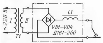
The control circuit is powered by 12 volts DC from its own source or from a 220 volt network through a quenching circuit. Such circuits are suitable for controlling powerful motors.
The principle of regulation with DC microcircuits is, of course, PWM - pulse width modulation. A transistor, for example, opens with a strictly specified frequency of several kilohertz, but the duration of the open state is regulated. So, by rotating the handle of the variable resistor, the rotation speed of the rotor of the commutator motor is set. This method is convenient for maintaining low speeds of a commutator motor under load.
Better control is direct current regulation. When PWM operates at a frequency of about 15 kHz, adjusting the pulse width controls the voltage at approximately the same current. Let's say, by adjusting the constant voltage in the range from 10 to 30 volts, they get different speeds at a current of about 80 amperes, achieving the required average power.
Speed controller for commutator motor on TDA1085:
If you want to make a simple regulator for a commutator motor with your own hands without any special requests for feedback, then you can choose a thyristor circuit. All you need is a soldering iron, a capacitor, a dinistor, a thyristor, a pair of resistors and wires.
If you need a higher-quality regulator with the ability to maintain stable speeds under dynamic loads, take a closer look at regulators on microcircuits with feedback that can process the signal from the tachogenerator (speed sensor) of a commutator motor, as is implemented, for example, in washing machines.
How to check zener diode
You can check the zener diode for serviceability quite simply and quickly using a simple multimeter. To do this, the multimeter should be switched to the “continuity” mode, usually indicated by a diode sign. Then, if we touch the anode with the positive probe of the multimeter, and the cathode with the negative probe, then on the display of the measuring device we will see a certain value of the voltage drop across the pn junction. Since direct voltage is applied to the semiconductor device (see the direct branch of the current-voltage characteristic), the reference diode will open.
Now, if the probes of the multimeter are swapped, thereby applying reverse voltage to the terminals of the semiconductor device (see the reverse branch of the current-voltage characteristic), then it will be locked and will not conduct current. The meter display will show a unit, indicating infinitely high resistance.
If in both cases the multimeter shows one or rings, then the zener diode is unusable.
Parts used
A TS70/5 transformer was used here (26 V - 2.28 A and 5.8 V - 1 A). Total 32 volts secondary voltage. In this version, uA741 opamps were used instead of TL081, since they were available. Transistors are also not critical - as long as they are suitable in current and voltage, and naturally in structure.
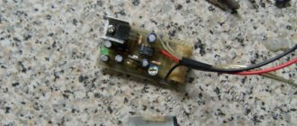
Printed circuit board with parts
The LED signals the transition to ST mode (stable current). This is not a short circuit or overload, but current stabilization is a useful function of the power supply. This can be used, for example, to charge batteries - in idle mode the final voltage value is set, then we connect the wires and set the current limit. In the first charging phase, the power supply operates in CT mode (the LED is on) - the charging current is set, and the voltage slowly increases. When, as the battery charges, the voltage reaches the set threshold, the power supply switches to voltage stabilization (SV) mode: the LED goes out, the current begins to decrease, and the voltage remains at the set level.
The maximum value of the supply voltage on the filter capacitor is 36 V. Watch its voltage - otherwise it won’t hold up and it will go boom!
Sometimes it makes sense to use two potentiometers to regulate current and voltage according to the principle of coarse and fine adjustment.
View of the indicators inside the case
The wires inside should be tied into bundles with thin cable ties.
Diode and transistor on the radiator