Almost all electronic devices operate on direct current. This approach significantly reduces the number of electronic components used, the size of the circuit and the cost of manufacturing the device.
Rectifiers are used to convert alternating electrical voltage into direct voltage. The article will give a detailed explanation of what full wave rectifiers are. Describes their operating principle, varieties, main advantages and disadvantages.
Purpose
The main purpose of a single-phase full-wave rectifier is to convert alternating current into direct current. In order to understand the principle of operation of such a rectifier, it is necessary to understand what half-wave rectification is.
A half-wave rectifier is a device that consists of a transformer and one diode (valve) connected to the secondary winding of the transformer. The device works as follows:
- Sinusoidal current is a cycle of 2 periods: positive and negative.
- When a positive half-cycle flows through the circuit, the diode opens and passes it further along the circuit.
- When a negative half-cycle occurs, the diode does not open and cuts off this cycle.
This way, only high ripple current is passed through the circuit. In order to smooth out this effect, the circuit is supplemented with a high-capacitance capacitor. The main disadvantage of this scheme is the large current loss and the need to use powerful smoothing capacitors. A similar device is used, for example, for mobile phone charging units.
A full-wave single-phase rectifier is built according to approximately a similar circuit. The main difference is the addition of 2 or more semiconductor diodes to smooth both half-cycles. There are the following types of such elements:
- Mostovoy.
- With a midpoint.
Each device uses a different number of converters, which means it has a different operating principle.
Half Wave Polyphase Rectifier
First, it is more convenient to consider three-phase half-wave rectifiers, which are easy to manufacture and are used in simple and inexpensive converter circuits. When constructing them, one powerful diode is installed in each phase, serving only this branch.
A total of three semiconductor diodes with loads connected to them are used in a half-wave rectifier device. After studying the diagrams of voltages and currents obtained at the output of the electrical circuit, the following conclusions can be drawn:
- the efficiency (efficiency) of such a device is very low;
- useful power is lost when processing negative half-waves of all three phases;
- When using such devices, it is very difficult to obtain the required load characteristics.
All these disadvantages of half-wave circuits forced developers to complicate them by applying the principle of double parallel conversion.
Midpoint diagram
A midpoint full-wave rectifier involves a transformer with two secondary windings having a central terminal. A transformer with one secondary winding can also be used, but it will necessarily have an output from the center of the winding. In addition, the circuit contains 2 diodes. A rectifier with a zero terminal works due to the formation of EMFs of different directions. Both of these EMFs are equal in magnitude to the generated voltage relative to the center or 0 point. When such a transformer operates, the current on both half-windings is shifted in phase by 180 degrees.
The operating principle of this rectifier is as follows:
- The transformer has terminals “w21” and “w22”, which have opposite meanings.
- The anodes of the valves “vd1” and “vd2” are connected to these pins.
- The voltage applied to each diode is in opposite phase (“u21”–“u22” in the diagram).
- During the first half-cycle, current flows through the open diode “vd1”. Only current with a positive potential flows through its anode. During this half-cycle, the diode “vd2” is in a reverse bias state. It is locked and does not allow current from winding “w22” to pass through.
- During the second half cycle, a current with a positive potential is present at the anode “vd2”, thereby opening the diode. The diode passes current through itself from the “w22” winding. The diode “vd1” remains closed.
A full-wave zero-point circuit operates due to the absence of a bias torque. Each half of the secondary winding operates at its own half-cycle, which means the transformer is in a state of constant load.
pros
The zero-output circuit has advantages only over the single-cycle rectifier model. The main advantages of this scheme:
- During operation, current is transferred from both potentials, thereby saving up to 90% of the original energy.
- 2 diodes evenly distribute the load, extending their service life and significantly reducing the load on the entire circuit.
- The full-wave rectifier circuit assumes a smoothed current ripple, without the use of high-voltage, capacitive capacitors.
Despite a number of advantages, single-phase rectifiers with two diodes have their disadvantages, which will be discussed below.
Minuses
To operate such a clutch, you definitely need a special transformer with 2 secondary windings or one separated, with zero output. Such devices greatly increase the costs of producing high-voltage, powerful devices.
Also a big disadvantage is the reverse current load. The circuit must use diodes with a rated voltage of up to 1000 volts and the ability to withstand temperatures up to +80 degrees. If these parameters are not met, then when the diode closes, an increased temperature and resistance will form. Exceeding the parameters will lead to breakdown of the diode itself.
The next disadvantage is the use of the zero tap itself. Connecting to it involves only using part of the available energy, which greatly reduces the potential of such devices.
How to organize bipolar power supply
By combining a balanced circuit and a bridge circuit, you can get a converter that will provide bipolar power at the output with a common (zero) point. Moreover, for one it will be negative, and for the other it will be positive. Such devices are widely used in power supplies for digital radio technology.
Diagram: example of a converter with bipolar output
Diode bridge
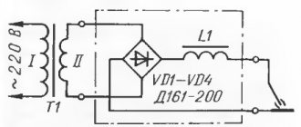
The second type is a full-wave bridge rectifier. This model is most common in circuits of household and industrial electronic devices. Electronic element composition:
- Transformer.
- 4 semiconductor diodes.
- Capacitor for smoothing pulses.
- Resistor as additional resistance.
The device operates using a bridge circuit as follows:
- 4 semiconductor diodes are connected to each other in a circuit. In other words, they form pairs.
- One side of each pair is connected to the terminals of the secondary winding of the transformer.
- The other two sides are connected to a circuit (load). In the case of the presented circuit, the load is the resistor “Rн”.
- When the first half-cycle is formed, the diodes “vd1-vd4” open and pass current to the load resistor Rн. The diode pair “vd2-vd3” is closed.
- During the second half cycle, 1 pair of diodes (vd1-vd4) is closed. The diodes “vd2-vd3” come into operation. They open and redirect the current to the resistor Rн.
With this type of operation, the effect of current ripple remains. It is smoothed out using a capacitive capacitor.
Advantages
Full-wave bridge rectification has one undeniable advantage over circuits with fewer diodes. It consists in the values of reverse rectified current and voltage. These values exceed the same parameters in other schemes by 2 or more times. Thus, the bridge circuit has significantly higher efficiency.
Minuses
The disadvantages of the diode bridge also lie in the number of diodes. Each of the 4 diodes maintains a reverse voltage in the closed position, which is equal to the voltage in the half-wave rectifier. Thus, 4 diodes do not help reduce the reverse current load on the secondary winding.
Despite the disadvantages, the bridge rectifier circuit is more common. It can be mounted as 4 diodes or in an assembly. Assembly looks like a more practical option. It takes up less space on the printed circuit board.
Description of rectifiers
Three-phase bridge rectifier
The main difference between the devices and their single-phase analogues is as follows:
- the first ones are installed in 220 Volt lines and are used to obtain direct currents of insignificant magnitude (up to 50 Amperes);
- three-phase rectifiers are used in circuits where operating (rectified) currents significantly exceed this figure and reach several hundred Amperes.
- Compared to single-phase samples, these devices have a more complex design.
There are known three-phase voltage rectification schemes that make it possible to obtain a minimum level of ripple at the output.
In electrical engineering, they are called “three-phase bridge rectifiers” because the way they open diodes, controlled by voltage polarity, they resemble a one-way bridge across a river. Only the direction of the flow of electrons in them alternates with a frequency of 50 Hz, which is inaccessible for cars to pass alternately in each direction.
Smoothing
A single-phase electrical full-wave rectifier, no matter how many diodes it combines, requires additional smoothing of the output voltage. Ripple greatly affects the operation of the device itself for which such a rectifier is assembled. To smooth out current ripple, the rectification circuit is supplemented with filters. They can be collected from:
- High-capacity capacitor. Such a filter is a capacitive or “C-filter”. At the moment the diode opens, the capacitor is filled with current and plays the role of capacitance. At the moment the diode closes, the capacitance is gradually discharged, thereby smoothing out the voltage without any surges.
- Inductors. An inductor as a filter can be used in addition to or instead of a capacitor. This filter operates on the principle that there is no instantaneous change in the current across the coil. As a positive half-wave passes through the coil, the current value increases smoothly and slowly. When the half-wave changes to a negative value, the current in the coil changes with a delay, which significantly reduces the sharpness of the pulsation.
When designing diode rectifiers, the load of subsequent circuit elements is taken into account. So, if the resistance after the rectifier is significantly low, then using a capacitive filter is not advisable. At low loads, a larger capacitor will be required. Thus, for such circuits with low resistance, it is more rational to use an inductive filter.
Using Op Amps
As is known, the current-voltage characteristic of diodes is nonlinear; by creating a single-phase precision (high-precision) full-wave rectifier on an op-amp chip, the error can be significantly reduced. In addition, it is possible to create a converter that allows you to stabilize the current on the load. An example diagram of such a device is shown below.
Circuit: a simple op-amp stabilizer
The figure shows a simple current stabilizer. The op amp used in it is a voltage controlled source. This implementation makes it possible to ensure that the current at the output of the converter does not depend on the voltage loss across the load Rн and the diode bridge D1-D4.
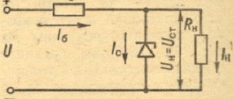
If voltage stabilization is required, the converter circuit can be slightly complicated by adding a zener diode to it. It is connected in parallel to the smoothing capacitance.
Diode Value Calculation
The diodes in full-wave rectifiers must withstand the load of alternating current, heat, and reverse voltage. When selecting a diode, you must consider:
- The output voltage to the diode should be 15–25% higher than the required value. For example, if you need to remove 12 volts of direct voltage, then the secondary winding of the transformer must produce at least 15–17 volts.
- The operating current threshold should be one and a half to two times higher than the rectifier current. The maximum current of each diode in the circuit can be found using the following formula:
- The value derived from the formula can be used to determine the value of the reverse voltage in the closing state. This value must be twice the output voltage of the transformer, otherwise reverse pn breakdown is possible. This is done according to the following formula:
It is also worth considering the material that is used as the semiconductor. Silicon elements are more resistant to reverse current loads and are capable of operating at temperatures up to +150 degrees. Germanium is less stable, its resistance to reverse voltage is about 400 volts.
Briefly about controlled converters
It is often necessary to control the voltage at the output of the converter without changing the input. For this purpose, the most optimal would be to use controlled valves; an example of such an implementation is shown below.
Simple thyristor converter (on controlled valves)
Design
Calculating even a simple full-wave converter is not an easy task. It can be significantly simplified using special software. We recommend choosing the Electronics Workbench program, which allows you to perform schematic modeling of analog and digital electrical devices.
By simulating a full-wave rectifier in this program, you can get a clear idea of the principle of its operation. Built-in formulas allow you to calculate the maximum reverse voltage for diodes, the optimal capacity of the quenching capacitor, etc.
Selecting a build type
For each task there is its own optimal version of the rectifier diode assembly. All of them can be divided into 3 types:
- Rectifier with one diode. It is used in the simplest and cheapest circuits where there is no c.l. requirements for the quality of the output voltage, as, for example, in night lights.
- Dual diode. These parts look similar to transistors, because they are produced in the same packages. They also have 3 pins. Essentially, these are two diodes placed in one housing. One of the conclusions is average. It can be the common cathode or the anode of the internal diodes.
- Full diode bridge. 4 parts in one case. Suitable for devices with high currents. It is mainly used on the inputs and outputs of various power supplies and chargers.
Additional Information. Rectifiers are also used in cars. They are needed to convert the alternating voltage coming from the generator to direct voltage. This, in turn, is necessary to charge the battery. A conventional gas generator produces alternating current.
Read also: Do-it-yourself shock absorber spring tensioner
Checking elements
In most cases, it is not necessary to unsolder the bridge from the board for testing. It should be tested in the same way as a 4 pn junction with a diode bridge connection. This measurement is so common that its capability is implemented in any multimeter. The test device must be switched to diode continuity mode.
The forward voltage drop across a working rectifier diode is 500-700 mV. Otherwise, the device will display “1”. A burnt part most often shows “0” in both directions, i.e. short circuit. Less often, a complete breakage of the element occurs (also in both directions). All measurements should be repeated for each diode included in the bridge. Total 8 measurements, i.e. 4 in forward direction and 4 in reverse. If a Schottky diode is tested, then this parameter is 200-400 mV.