Electrical installation and commissioning work is always associated with measuring the characteristics of the electrical network, checking the presence of voltage and the operability of the circuits of a device or line. There are a huge number of different measuring instruments and testers for these purposes, but the most versatile and useful device for home craftsmen and professionals is a multimeter. In this article we will look at how to use it.
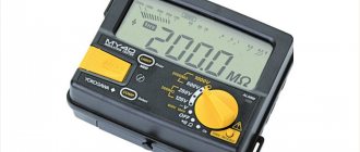
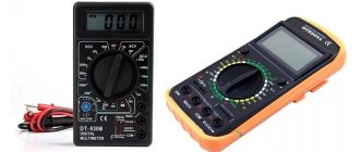
Appearance of the multimeter
A multimeter is a universal device for measuring electrical characteristics that combines many functions (depending on the model). In the minimum configuration, such a device consists of an ammeter, voltmeter and ohmmeter. In the most common version, it is performed digitally and portable. Externally it has a rectangular shape with a display and a rotary or push-button function switch. To perform measurements, two probes (red and black) are connected to the multimeter in strict accordance with the markings on the device.
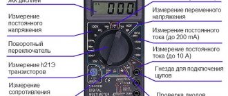
Brief description of the measured parameters and their designation
Manufacturers use standard markings in English or special symbols to indicate parameters on multimeters. To operate the device, it is important to know the basics of electrical engineering in order to correctly and safely carry out the necessary measurements.
Each device is divided into zones with settings for working with a certain type of electrical network voltage:
- ACV or V~ – alternating current voltage;
- DCV or V- – DC voltage;
- DCA or A- – direct current strength;
- Ω is the resistance in a section of a circuit or in an electrical device.
Purpose of connectors for connecting probes
Depending on the multimeter model, the number of sockets for connecting probes may vary. It is necessary to connect the probes for measuring the electrical parameters of the network into the correct sockets of the device. For most measuring instruments, the sockets are marked as follows:
- 10A- – for measuring direct current not exceeding 10 A (a red positive probe is connected to this socket);
- VΩmA or VΩ, V/Ω - a red (positive) probe is connected to this socket when determining voltage, direct current up to 200 mA, for continuity testing of diodes and circuits;
- COMMOM (COM) – common socket for the black (negative) probe on all types of multimeters;
- 20A - such a socket does not exist on all models (most often it can be found on expensive professional devices), the task of this socket is similar to 10A-, but with a limit of up to 20 A.
Security measures
Any manipulation with electricity poses an increased danger. Including working with a multimeter. Moreover, you often have to work with exposed wires. Therefore, the following safety precautions must be observed:
- all work must be carried out only by protecting your hands with rubber gloves, this will protect not only from electric shock, but also from burns;
- before connecting the multimeter to the network, you must make sure that it is de-energized;
- when working with wires connected to the device, you need to constantly monitor the integrity of their insulation, which is often broken during intensive use of the multimeter;
- It is prohibited to take measurements during rain or when there is strong humidity in the room;
- manipulations with electricity must be carried out in the presence of an assistant who can provide assistance or call doctors if an accident occurs.
At the end of the measurements, the network is de-energized again and only after that the disconnected wires are connected.
Now, having read the article and understood the device, as well as the principles of operation of the measuring device, anyone can easily take measurements. However, it will be better if this is done by a trained professional.
How to measure voltage
For a person who has certain skills and knowledge in electrical engineering, it will not be difficult to take measurements using a multimeter. For those who have never worked with this type of device, below is how to use a standard multimeter.
Important! All work must be carried out by specialists or people with certain skills in electrical engineering. Remember that electric shock is life-threatening!
Constant pressure
Using this mode, the voltage of batteries, batteries and car batteries is measured. Most control circuits in modern process control systems have a 24 V DC potential.
In order to perform a measurement in this mode, it is necessary to switch the device to the DCV position, while measuring (if you do not know the approximate voltage) is best to start with the maximum value of the switch, gradually reducing the range until the desired dimension is obtained. If the measurement result is displayed on the device screen with a “minus” sign, then the polarity of the probe connection has been violated (this means that the “minus” was connected to the “plus” of the circuit in which the measurement is being made, and the “plus” to the “minus”).
As for the dimension, everything is simple: if, for example, the number 003 is displayed on the screen, then it is necessary to reduce the measurement range. Gradually reducing the voltage using the switch, 03, 3 will be displayed.
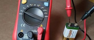
Charger and adapter measurements
Battery rechargers and power supplies are used with many modern gadgets. True, their purpose is different. Power supplies are designed to convert voltage to one suitable for the operation of the connected gadget. The charger is used to replenish batteries with electricity. It is necessary to know their characteristics in order not to damage an expensive device in case of failure of a standard device.
So, to measure current values in a circuit with an adapter or charger, you need to set the measurement limit in the range from 1 A to 10 A. The multimeter is connected in series to the circuit. If the readings are zero, you need to swap the probes or clamps.
We measure the current strength
To do this, you need to know what current we will measure: direct or alternating. Most standard multimeters can measure DC current, but AC current requires multimeters with a clamp meter.
D.C
To do this, move the multimeter switch to DCA mode. The red probe should be connected to the socket marked “10 A”, and the black one to “COM”. If the value of the measured current is up to 200 mA, then for greater accuracy of readings, we move the red probe into the 200 mA connector. In any case, in order not to burn the device, it is best to start measurements with the probe in the 10 A connector and, if necessary, rearrange it. We do the same with the switch: first we set the highest current, gradually reducing the range to obtain the desired maximum limit to a minimum value of 2000 microamps.
Note! To measure direct electric current, the multimeter probes are placed at an open circuit.
You need to know that the multimeter probes are connected to an open circuit. That is, the red probe is installed on the “plus” of the power source, and the black one on the “positive” conductor.
Alternating current
The value of alternating current can be measured by a multimeter that contains special current clamps.
The operating principle of current clamps is based on the phenomenon of electromagnetic induction. The measurement is carried out in a non-contact manner by placing a conductor in an electromagnet with a secondary winding. The primary current (measured) is proportional to the secondary (which occurs on the winding). Therefore, the device easily calculates the desired value of the primary alternating current.
Measurement process
To measure, you need to connect to the open circuit between the network and the connected device that consumes current. The connection is made in series, as opposed to voltage measurement.
As it became clear, to connect to the circuit under test, it needs to be broken. This is done in several ways:
- You can disconnect the output by soldering the contacts;
- unscrewing the screw connections;
- cutting the wires with wire cutters.
Thus, the multimeter becomes an integral part of the electrical circuit. After correct connection, the arrow will show the current strength in the circuit. And the display will display specific numbers.
Measuring resistance
To measure resistance, set the switch to resistance mode (Ω) and select the desired range. One of the probes is applied to one input of the resistor, the other to the other. The display will show the resistance value. By switching the range you can get the desired dimension of the resistance value.
If “zero” is displayed on the display, then the range should be reduced, and if “1” then increased.
What will it show if the socket is faulty?
If there is no network, the multimeter will read 0 Volts.
The reason is a faulty socket or lack of electricity. To determine the cause, you need to ring other outlets in the room. If only one does not work, its contacts are checked and, if necessary, replaced with a new one. During voltage surges, the values on the multitester will differ greatly from the nominal 220 Volts. According to GOST, a deviation of 10% is permissible; a larger deviation can lead to damage to electrical appliances. If a strong voltage surge is detected, it is worth installing an additional stabilization device in the apartment. The home network operates at a voltage of 220 Volts, but in the outlet it may differ from the nominal value. Voltage within the limits established by GOST is the key to high-quality and stable operation of household appliances. It is important to be able to check voltage using a multitester to prevent the risk of damage to electrical devices. If there is a significant deviation from the set values, care should be taken to stabilize the voltage in the room.
How to test wires with a multimeter
Continuity of wires means determination of integrity. Essentially, the multimeter determines the resistance of a closed circuit and if this value is close to zero, then the circuit is considered closed and an audio signal is issued. Not every multimeter can ring wires with sound, but most of them are capable of it.
Continuity testing is a check of the integrity of the circuit. To test the wires, the multimeter is set to the desired mode. Most often it is combined with diode testing, but can be taken out separately and marked with a bell sign. Next, one probe is applied to one end of the conductor, and the other probe to the other. In this case, a signal sounds or an indication appears in the light or on the display. If there is an indication, the circuit is not broken; if not, then the conductor is damaged or the circuit is broken.
Features of measurements
There are several points that are tricks of professionals that they use when taking measurements. One of them is to use a device with a certain resistance with a multimeter. It could be an ordinary light bulb or a resistor. They protect the measuring device from burning out when excessive current is supplied.
If, when connecting the multimeter to the circuit, the current indicators are not displayed, then you need to check whether the limit is selected correctly. You can try lowering the limit by lowering it one more position. If nothing has changed, then the limit is reduced again. This must be done until the value obtained during the measurement appears on the device indicator.
Measurements must be taken quickly. The duration of contact with the electrically conductive cable should not exceed 2 seconds. This mainly concerns measurements of small-capacity power supplies. Prolonged contact results in discharge of the battery or accumulator.
Devices used
In every home, the electricity meter is in a state of constant measurement of alternating voltage, but it is extremely rare that this data is displayed anywhere. Some of them are connected directly, others through instrument transformers.
For practical purposes, the following can be used to measure voltage levels:
- Voltmeters;
- Multimeters
- Oscilloscopes.
A voltmeter is a device for testing potential differences. In practice, you can find both digital and analog voltmeters, in which the measured voltage is displayed on the display or by deflecting the arrow on the dial, respectively.
Important parameters when choosing both an electronic and a pointer voltmeter are units of measurement (mV, V, kV), operating range and accuracy class. However, the scope of their application is limited and is used, most often, for laboratory research, since for domestic and industrial needs it is impractical to maintain one device for measuring one electrical quantity.
A multimeter or digital tester is a more versatile device that can work with several parameters: electric current, resistance, frequency, temperature, voltage, etc. To measure voltage, the multimeter switches to voltmeter mode, the probes are connected to the appropriate connectors. Structurally, there are both digital and analogue models, in some of them you can switch the measurement range, select the type of current, in other multimeters all these values can be selected automatically.
An oscilloscope is a rather complex instrument for measuring potential differences, since it displays a curve of the measured value on a digital or analog display. In this case, you can stretch or shorten the frequency range to consider the shape of the pulse voltages, pulse duration, rises and dips in the function curve. Therefore, an oscilloscope for measuring voltage is used in electrical circuits and high-precision devices, in the manufacture and testing of radio components, etc. Few people keep an oscilloscope at home due to the high cost and complexity of operations.