The question of how to check a voltage stabilizer is relevant for many enterprises, organizations and private users. Stabilizing devices are quite complex equipment, the quality of which determines the serviceability of the connected expensive equipment. Therefore, monitoring their performance and timely detection of faults is a necessary condition for ensuring uninterrupted technological processes and minimizing additional costs.
Stabilizer malfunctions
The most important characteristics of stabilizers that are subject to control are the rated input and output voltage, load current, degree of stabilization, ripple value, and temperature of internal components. To fully diagnose these parameters, special equipment is required. Testing devices using triac switches is considered especially difficult. It requires precise circuitry and specialized measuring instruments, including an oscilloscope.
Let's look at some common problems with stabilizers:
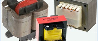
- In relay devices, most often the relays that are responsible for switching the transformer windings fail. Also sometimes the coil burns out.
- The transformer overheats without a serious load. This problem occurs due to turn-to-turn short circuit or short circuit in the switches.
- Overheating of the servo stabilizer. It can occur due to the short circuit of adjacent turns due to contamination of the contact pads. To prevent this, devices must be periodically disassembled and cleaned.
- Burnout of one of the electronic components. It can occur due to short circuits, overloads, or excessively high temperatures.
78l05 switching diagram
78l05 switching circuit is the most popular five-volt voltage stabilizer, an analogue of the low-power microcircuit 7805. This article publishes a description, parameters and the switching circuit of the 78L05 device. In essence, almost every company in the world that creates integrated circuits has released its own analog element of this chip. The definition of the manufacturer of this electronic element is read by the first two letters, for example: LM78L05 (TAIWAN SEMICONDUCTOR), TS78L05 (TAEJIN Technology HTC Korea).
Naturally, in order to know the exact parameters of an electronic device, for this, of course, you need to use the official datasheet. Although the official specification 78l05 circuit diagram has some nuances, in particular, this is the presented sketch of the pinout arrangement, which is not graphically clear enough. And when you have to make any repairs or adjust the device, you have to look at two images at the same time.
That is, determine the name and serial number of the pin and additionally look where the pin is located on the body itself. Despite the fact that on this chip pin number 1 is the output bus, and the last pin is the input bus, in practice it confused me several times. As a result, I did the PCB layout incorrectly. In order not to repeat such oddities in the future, I applied the pin designations directly to the housing sketches: TO-92, SOT-89, SO-8.
How to check the electrical stabilizer?
To troubleshoot the device, you need to do the following:
- Preliminary check. It can be carried out without special devices. To do this, you will need two table lamps of the same power, an electric stove or other powerful consumer, and a power extension cord with several sockets. We connect a stabilizer, one light bulb and an electric stove to the extension cord. We power the second light bulb from the stabilizer. Turn on the tile. If the stabilizer works correctly, then the light of the lamp connected to it will not change, but the light of the lamp connected to the extension cord will decrease.
- Disassembling the equipment, thoroughly removing all contaminants, cleaning the contact pads to a metallic shine.
- Inspection of the stabilizer, identification of electronic components with traces of exposure to high temperature. Overheated resistors look charred, and blackening and cracks may appear on the transistors. You also need to pay attention to swollen capacitors. Another symptom of overheating is a change in the shade of the textolite board.
- Ringing of power switches and other components.
Purpose of inspection
Voltage stabilizer is a device used as an input device. It is placed in front of the counter. Used in networks with one, two and three phases. Can be used for one electrical appliance with a power of more than 6 kilowatts. Three-pole can be used for equipment over 9 kilowatts.
Most often it is used to protect household electrical or heating appliances. It can also be used to protect lighting system, motor, transformer and industrial electronic appliances.
Note! It is necessary to check the voltage stabilizer so that it can work properly and help the user protect the electrical circuit from overvoltage, short circuit and other troubles. This must be done, since sometimes the stabilizer itself can cause damage to the electrical circuit and all household equipment.
Checking the functionality of the circuit protection device
Checking a linear DC voltage regulator using a multimeter
One of the main components of a linear DC voltage regulator is a Zener diode or Zener diode. Failure of this particular element is the most common cause of device failure. Before you figure out how to test a voltage stabilizer with a multimeter, you need to understand the principle of operation of a zener diode. In operating condition, it passes current strictly in one direction. As the input voltage increases, the amount of electric current passing through the zener diode increases sharply. The element begins to operate in breakdown mode, ensuring that the output voltage is maintained with a given accuracy. Excessive currents lead to overheating and damage to the zener diode.
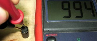
To check the component, connect the positive probe of the multimeter in resistance measurement mode to the cathode terminal, and the negative probe to the anode terminal. The device must show a certain resistance value. After this, we swap the probes. Resistance must become endless. Such multimeter readings indicate the serviceability of the zener diode. If during both measurements the device showed infinite resistance, the element broke. In the case when the resistance at different positions of the probes is zero, we can conclude that the zener diode has broken down.
Is it possible and necessary to check the stabilizer with a multimeter?
We've sorted out the zener diode, but how to check the electrical stabilizer? The same one that is installed at home to protect household appliances and electronics.
The voltage stabilizer is a complex device operating under the control of a microcontroller. The presence of “brains” in the circuit allows the device to independently control its state, reporting an error and de-energizing the load in the event of a malfunction. Error messages can have a variety of formats: a red LED, a code on an LED display, or a full message on a graphic or LCD display. If something happens to the stabilizer, you will definitely find out about it even without a multimeter.
Most often, malfunctions occur in relay and servo-drive stabilizers, since in the first case something can happen to the relay, and in the second - to the current-collecting brush or servomotor. The maximum that an ordinary user with a multimeter in hand can do in this situation is to ring the contacts and relay coils, although, in an amicable way, you should immediately contact the service center for the help of specialists. Inept actions can harm not only the stabilizer, but also yourself. There is no point in talking about interfering with the control scheme.
Checking according to the stabilizer circuit
The above method is not suitable for bi-directional and precision zener diodes. How to check the voltage stabilizer in this case? It is necessary to include the electronic components being tested in the circuit and apply voltage from the power source. To do this, you need a divider, which consists of one or more resistors. The resistor must ensure breakdown of the zener diode when voltage is applied from the power source.
Check procedure:
- The positive wire from the power supply is connected to the first terminal of the divider.
- The cathode terminal of the zener diode is connected to the second terminal of the divider.
- The anode terminal of the zener diode is connected to the negative terminal of the power supply.
- A multimeter in voltmeter mode is included in the circuit. The positive terminal is connected to the second terminal of the resistor, and the negative terminal is connected to the common power bus (negative terminal of the power supply).
- If a voltage equal to or greater than the stabilization voltage is applied to the first terminal of the divider, then at the output it should not exceed this value. This indicates a working zener diode. If the element is broken or incorrectly connected, the voltmeter will show zero. In the case of a broken zener diode, the multimeter readings will exceed the stabilization voltage.
Precision and double-sided devices
Precision zener diodes are tested in a similar way. Double-sided zener diodes are connected to the terminals of the power source without observing polarity.
To check the stabilizer, you need to switch the multimeter to DC measurement mode, observing the polarity. Initially, the amount of power supplied to the stabilizer is checked .
If the voltage is normal, then the multimeter is directly connected to the output of the stabilizer, measuring the voltage value at the output.
Voltage regulator
A voltage stabilizer is the most important radio element of modern radio-electronic devices. It provides a constant voltage at the output of the circuit, which is almost independent of the load.
Stabilizers of the LM family
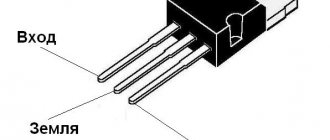
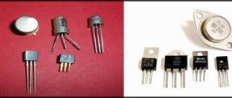
In our article we will look at voltage stabilizers of the LM78XX family. The 78XX series is produced in metal cases TO-3 (left) and in plastic cases TO-220 (right). Such stabilizers have three terminals: input, ground (common) and output.
Instead of “XX”, manufacturers indicate the stabilization voltage that this stabilizer will give us. For example, a 7805 stabilizer will produce 5 Volts at the output, 7812 will produce 12 Volts, and 7815 will produce 15 Volts. Everything is very simple.
Connection diagram
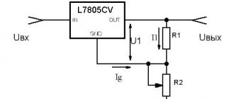
And here is the connection diagram for such stabilizers. This circuit is suitable for all stabilizers of the 78XX family.
In the diagram we see two capacitors that are sealed on each side. These are the minimum values of capacitors; it is possible, and even desirable, to supply a higher value. This is required to reduce ripple at both the input and output. For those who have forgotten what ripple is, you can look at the article on how to obtain a constant voltage from an alternating voltage.
Characteristics of LM stabilizers
What voltage should be supplied for the stabilizer to work as it should? To do this, we are looking for a datasheet for stabilizers and studying it carefully. We are interested in these characteristics:
Output voltage – output voltage
Input voltage – input voltage
We are looking for our 7805. It gives us an output voltage of 5 Volts. Manufacturers noted a voltage of 10 volts as the desired input voltage. But it happens that the output stabilized voltage is sometimes either slightly underestimated or slightly overestimated.
For electronic trinkets, fractions of volts are not felt, but for precision (accurate) equipment it is better to assemble your own circuits. Here we see that the 7805 stabilizer can give us one of the voltages in the range of 4.75 - 5.25 Volts, but the conditions must be met that the output current in the load will not exceed 1 Ampere. An unstabilized DC voltage can “fluctuate” in the range from 7.5 to 20 Volts, while the output will always be 5 Volts.
The power dissipation on the stabilizer can reach up to 15 Watts - this is a decent value for such a small radio component. Therefore, if the load at the output of such a stabilizer consumes a decent current, I think it’s worth thinking about cooling the stabilizer. To do this, it must be placed on the radiator through KPT paste. The greater the current at the output of the stabilizer, the larger the radiator should be. It would be generally ideal if the radiator was also blown by a fan.
LM work in practice
Let's look at our ward, namely the LM7805 stabilizer. As you already understand, at the output we should get 5 Volts of stabilized voltage.
Let's assemble it according to the diagram
We take our Breadboard and quickly assemble the connection diagram suggested above. The two yellow ones are capacitors, although it is not necessary to install them.
So, wires 1,2 - here we drive the unstabilized input DC voltage, remove 5 Volts from wires 3 and 2.
On the Power Supply we set the voltage in the range of 7.5 Volts and up to 20 Volts. In this case, I set the voltage to 8.52 Volts.
And what did we get at the output of this stabilizer? 5.04 Volts! This is the value we will get at the output of this stabilizer if we supply voltage in the range from 7.5 to 20 Volts. Works great!
Let's check one more of our stabilizers. I think you have already guessed how many volts it is.
Checking the functionality of the L7805CV
How to check the functionality of the microcircuit? To begin with, you can simply ring the terminals with a multimeter; if in at least one case a short is observed, then this clearly indicates a malfunction of the element. If you have a power source of 7 V or higher, you can assemble a circuit according to the datasheet given above and apply power to the input; at the output, use a multimeter to record the voltage at 5 V, so the element is absolutely operational. The third method is more labor-intensive if you do not have a power source. However, in this case, you will also receive a 5 V power supply in parallel. It is necessary to assemble a circuit with a rectifier bridge according to the figure presented below.
To check, you need a step-down transformer with a transformation ratio of 18 - 20 and a rectifier bridge, a further standard kit, two capacitors for the stabilizer and that’s it, the 5 V power supply is ready. The capacitor values here are overestimated in relation to the L7805 connection diagram in the datasheet, this is due to the fact that it is better to smooth out voltage ripples after the rectifier bridge. For safer operation, it is advisable to add an indication to visualize the device being turned on. Then the diagram will look like this:
If there are a lot of capacitors or any other capacitive load on the load, you can protect the stabilizer with a reverse diode to prevent the element from burning out when the capacitors are discharged.
The big advantage of the microcircuit is its fairly lightweight design and ease of use, if you need power of one value. Circuits sensitive to voltage values must be equipped with such stabilizers to protect elements sensitive to voltage surges.
