A light diode is a semiconductor device that is similar in design to a standard diode. A characteristic feature of each radiant diode is the low reverse voltage limit, which is only a couple of volts higher than the loss of voltage drop across it in the open position.
Any electrostatic discharge or incorrect switching on during the circuit setup process can cause the LED to fail. Ultra-bright, low-current light diodes used to indicate power supplies in a variety of installations can burn out due to power surges.
Known causes of ICE damage:
- Poor contact and faulty wiring causing sincere. This defect can occur in the electrical switch, distribution box and in the lighting equipment itself.
- Inexpensive lighting devices. Approximately a third of the energy used by LED diodes is spent on lighting, the rest is used for heating. The latter harms the crystal, causing its rapid degradation. In inexpensive diode chandeliers, the manufacturer most often does not include in the calculations for the design the necessary parameters to ensure its cooling.
Low consumer quality of the LED lamp. Negative nodes can be:
- current source;
- light diode;
- completed layout and design of the body, for example, a flashlight.
Classification
Diodes are simple semiconductor radioelements based on a pn junction. The figure shows a graphical representation of the most common types of these devices. Anode o, cathode - “-” (given for clarity; in the diagrams, a graphic designation is sufficient to determine the polarity).
Accepted notations
Types of diodes shown in the figure:
- A – rectifying;
- B – zener diode;
- C – varicap;
- D – microwave diode (high voltage);
- E – reversed diode;
- F – tunnel;
- G – LED;
- H – photodiode.
Now let's look at verification methods for each of the listed types.
HOW TO CHECK AN LED FOR OPERATION WITH YOUR OWN HANDS
To test a diode light bulb, you first need to determine what will be used to test it. You will need to purchase a power supply (PS) with an operating voltage ranging from 6.0 to 10.0 V. There is no need to rush to connect a light diode to it.
The next step is to purchase a resistor with a value that limits the current, with a voltage in the range of 6-12 mA. The diode is removed from the circuit for testing. Then when in an electrical circuit, with a resistor connected in series to the LED diode, there is a voltage drop of approximately 2 V, then the resistor is from 3 to 10 V. In the case of using a 5/12 V IP, for an electric current of 5 mA, according to Ohm triangle, you will need a resistance of 0.600 kOhm or 2 kOhm, respectively. Select a limiting value, for example, 0.560 kOhm and 2.1 kOhm for a 5/12 V power supply. Connect the LED through a resistor in series with the power supply.
Diagnostics of the serviceability of the zener diode
A zener diode is a semiconductor element that stabilizes voltage in a fairly narrow range. At the same time, different currents, both large and small, can flow through it. The voltage stabilization range of a zener diode is usually limited to one hundred millivolts. Structurally, a zener diode is a diode, and in direct connection it works that way. It stabilizes the voltage when voltage is applied to it in reverse connection. You can check the serviceability of a zener diode with a multimeter in the same way as you can check the serviceability of a conventional diode.
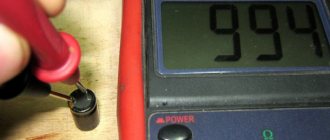
HOW TO CHECK WITH A MULTIMETER
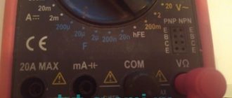
A multimeter is a universal measuring instrument. With its help you can measure the basic parameters of almost any electronic product and more. To check the LED, you will need a multimeter that has a “testing” mode, or it is also called a diode testing mode. The designation of the diode test mode on the multimeter is shown in the image below.
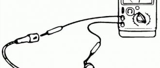
There is a simple method for testing a light diode with leads, using a multimeter with the option of measuring the characteristics of PNP and NPN transistors.
In order to ring the LED using this option, you need to insert it into the opening “C” and “E” of the transistor test connector: in PNP - the extended one with the lead in “E”, the shortened one in “C”. Into the NPN socket, with the long end in “C” and the short end in “E”.
A working diode will light up, since the power supply supplies it with 1.5 V, which is enough to weakly but noticeably illuminate the LED.
Another simple way to test is to test an LED vertebra with a multimeter, like a standard diode:
- Before checking the LED strip for functionality, run the multimeter to check the diode.
- Then you need to ring the LED diode by touching its legs with the tester probes.
- The working diode strip will light up slightly, and on the multimeter panel the user will see the drop number at the PN junction, V.
Additional Information! This method is not suitable for devices with high voltage, but weak ones, including SMD LEDs and an infrared flashlight, can be tested using a similar simple method, including when they are firmly installed on a printed circuit board.
Schottky diode assemblies in computer power supplies
During the assembly of power supplies and voltage converters for car amplifiers, a problem often arises with rectifying the current from the transformer. Getting hold of powerful pulsed diodes is quite a serious problem, so I decided to publish an article that provides a complete list and parameters of powerful Schottky diodes. Some time ago, I personally had a problem with the converter rectifier for a car amplifier. The converter is quite powerful (500-600 watts), the output voltage frequency is 60 kHz, any common diode that can be found in old trash will immediately burn out like a match. The only available option at that time was the domestic KD213A. The diodes are quite good, they hold up to 10 Amps, the operating frequency is within 100 kHz, but they also overheated terribly under load.
In fact, powerful diodes can be found in almost everyone. A computer power supply is a switching power supply that powers the entire computer. As a rule, they are made with a power from 200 watts to 1 kW or more, and since the computer is powered by direct current, this means that the power supply must have a rectifier. Modern power supplies use powerful Schottky diode assemblies to rectify the voltage - they have a minimal voltage drop across the transition and the ability to work in pulsed circuits, where the operating frequency is much higher than the network 50 Hz. Recently they brought several power supplies for free, from where the diodes were removed for this short review. In computer power supplies you can find a variety of diode assemblies; there are almost no single diodes here - in one case there are two powerful diodes, often (almost always) with a common cathode. Here are some of them:
D83-004 (ESAD83-004)
— A powerful assembly of Schottky diodes, reverse voltage 40 Volts, permissible current 30A, in pulse mode up to 250A - perhaps one of the most powerful diodes that can be found in computer power supplies.
STPS3045CW
— Dual Schottky diode, rectified current 15A, forward voltage 570 mV, reverse leakage current 200 μA, reverse voltage constant 45 Volts.
CHECKING LEDS WITHOUT DESOLDERING
In order to connect the multimeter probes to the PNP connection, you will need to solder a small section of a typical paper clip onto them. Between the legs on which the paper clips are soldered, a small fiberglass gasket is installed for insulation and wrapped with insulating tape. In a similar way, a structurally simple and safe multimeter adapter is obtained for connecting probes.
Before checking the LED with a multimeter without desoldering, you will need to connect the probes to the legs of the LED diode. To test a LED diode, you can use one standard battery. The connection is made in exactly the same way, only instead of an adapter, you can use small alligator clips to connect to the terminals of the probe battery. In this case, you will not have to solder the diode.
Specifics of the dialing mode
A multimeter is a universal tester that can be used to test light-emitting diodes and other elements. During operation, the device makes a squeaking or ringing sound, which is why the mode is called ringing.
Operating a multimeter in dialing mode has several features:
- the switch is placed to check the diodes, the probes are thrown onto the contacts;
- the polarity of the terminals is determined, but if it could not be detected, the LED light source will not fail;
- when the probes are correctly connected to the contacts and the correct polarity, the working diode will light up;
- during the dialing process, no current with a large value is supplied, so the backlight of the diodes is visible only in a darkened room;
- if there are difficulties with dimming the lighting, look at the device display - the indicator of the working SMD is different from 1;
- high-power LEDs without desoldering are tested after adding adapters.
Before starting work in ringing mode, determine the anode and cathode of the light source being tested.
Features of checking LED light bulbs
Using a multimeter, you can test color, standard and super-bright diodes.
Standard light bulb with E27 base
A similar lamp is used for household chandeliers or lamps. To check whether an LED is working or not working, you will need:
- Remove the diffuser from the light bulb using a plastic bank card placed between the element and the body.
- Carefully move the plastic card along the glue. A durable seam can be heated with a hair dryer.
- Open the board.
- Touch the elements with probes and wait until they glow with a dim glow.
If the diodes do not light, the light bulb is broken.
Super bright diodes
The garland is usually equipped with blue, yellow or white LEDs. The test is carried out without probes using transistor sockets according to the following algorithm:
- Determine the pinout of the SMD.
- Find 8 sockets at the bottom of the device - 4 left ones for PNP transistors and 4 right ones for NPN transistors.
- Place the probes by inserting the anode into hole E and the cathode into hole C.
- Open the PNP element by applying a positive charge to the emitter E. A working LED will light up.
- Change the polarity of transistors for NPN. The anode is placed on C, the cathode - on E.
Transistor sockets are useful for testing diodes with long contacts without solder.
How to check an LED spotlight
The LED is checked after determining the type of element. The following are installed on the lanterns:
- a board with small SMDs, which are checked by continuity in the same way as a standard light bulb;
- a large yellow element operating on a voltage of 10-30 V.
The voltage of a large element is high for the tester, so the operability of the element can only be determined by the driver. It must match the performance of the diode.
Nuances of testing infrared diodes
The infrared LED emits invisible radiation, so it is important to monitor the readings on the multimeter display. The probes are installed by applying plus to the anode and minus to the cathode. By touching the probes to the working IR diode, you can see the number 1000 on the screen. When the polarity is changed, 1 is displayed.
To accurately check the infrared diode with transistor sockets, a smartphone camera or digital device is used. The IR LED will need to be placed in the transistor sockets and the camera pointed at it. Serviceability is indicated by a glowing blurry spot on the gadget’s display.
Soldering a parallel red LED glow will clearly reflect the performance of the diode. If a signal is supplied to the element at the moment of flickering, it should be replaced. If the backlight does not work, the remote control is faulty.
Checking the LED Bridge
Diode bridge – assembly of 4 elements. They are connected so that AC voltage is supplied to two of the 4 terminals, turns into DC voltage and is removed from the other 2 terminals. Zener diodes equalize voltage within a narrow range.
You can ring the LED bridge like this:
- Find which pin to connect the multimeter to by making a conditional numbering.
- Ring the first diode by placing probes on pins 1 and 2.
- Test the second LED by connecting probes to pins 2 and 3.
- Measure the parameters of the third diode by connecting probes to pins 1 and 4.
- Determine the serviceability of the fourth element by placing probes on pins 4 and 3.
- View the readings on the scoreboard.
Voltage stability is checked in the maximum range mode - 220 V. It is increased gradually and stopped supplying until current flows through the circuit.
You will need to place the black probe on the anode, the red one on the cathode, and then connect the anode to the current limiting resistor, and the cathode to the power source.
Checking the infrared diode
There is an IR diode in every remote control (television or other device). The procedure is exactly the same as in the case of testing a conventional LED with a multimeter. But checking an infrared diode is more difficult, since it is impossible to see its glow with the naked eye. When you press a button on the remote control, nothing happens externally.
Similar diodes are used to illuminate surveillance cameras in night mode. You can use your phone's camera, which sees the glow and will help resolve the issue with visual control. If you need to check the general condition and determine the source of the problem, you can simply solder a regular LED in parallel. If it starts to blink, then the IR diode is to blame, and if this does not happen, the cause of the malfunction is in the remote control itself.
Diodes used in power supplies. Selection and replacement.
Hi all . So I thought about it and compiled a short list of diodes used in power supplies. In your favorite power supply, replace a pair of diodes (if the overall power of the power transformer allows) and the power of the power supply from 250 watts will become 300. And 300 watts will become 350.
DIODES t=25 deg. Schottky TO-220 SBL2040CT 10A x 2 =20A 40V Vf=0.6V at 10A Schottky TO-247 S30D40 15A x 2 =30A 40V Vf=0.55V at 15A ultrafast TO-220 SF1004G 5A x 2 =10A 200V Vf=0.97V at 5A ultrafast TO-220 F16C20C 8A x 2 =16A 200V Vf=1.3V at 8A ultrafast SR504 5A 40V Vf=0.57 Schottky TO-247 40CPQ060 20A x 2 =40A 60V Vf=0.49V at 20A Schottky TO-247 STPS40L45C 20A x 2 =40A 45V Vf=0.49V ultrafast TO-247 SBL4040PT 20A x 2 =40A 45V Vf=0.58V at 20A Schottky TO-220 63CTQ100 30A x 2 =60A 100 Vf=0.69V at 30A Schottky TO-220 MBR2545CT 15A x 2 = 30A 45V Vf=0.65V at 15A Schottky TO-247 S60D40 30A x 2 =60A 40-60V Vf=0.65V at 30A Schottky TO-247 30CPQ150 15A x 2 =30A 150V Vf=1V at 15A Schottky TO-220 MBRP3045N 15A x 2 =30A 45V Vf=0.65V at 15A Schottky TO-220 S20C60 10A x 2 =20A 30-60V Vf=0.55V at 10A Schottky TO-247 SBL3040PT 15A x 2 =30A 30-40V Vf=0.55V at 15A Schottky TO -247 SBL4040PT 20A x 2 =40A 30-40V Vf=0.58V at 20A UltraFast TO-220 U20C20C 10A x 2 =20A 50-200V Vf=0.97V at 10A
Fast round FR101-107 1A 30A 50-1000V Vf=1.3V Fast FR151-157 1.5A 50A 50-1000v Vf=1.3V Fast FR201-207 2A 70A 50-1000V Vf=1.3V Fast PR1001-1005 1A 30A 5 0-600V Vf=1.2V Fast PR1501-1507G 1.5A 50A 50-1000V Vf=1.3V Mikhail.
PS. About the selection of diodes——- ——— Sometimes it becomes difficult to decide which diode to choose or what to replace the diode with. How to choose a diode, what parameters to compare diodes by. It seems that everything is simple, you need to set the same or better parameters. The diode parameters are indicated for sinusoidal current and when operating in pulsed circuits the parameters are slightly lower in current and voltage. Next, the total current of both diodes is indicated, but in fact half a period through one diode and another half a period through the second diode, 10A - 1 diode + 10A - 2 diode = equal to 10A total current to the load, and the diode says 20A total current. The next parameter, the voltage drop across the open diode, is denoted by Vf, PW = IA multiplied by U Vf. From this formula you can find out the following: how much power will be released on the diode when the selected current flows through it. When 2 diodes are connected in parallel, the current flowing can be increased, and the internal resistance decreases, the voltage drop across the open diode also decreases, and the power dissipation on the diode also decreases. Diodes heat up less. Guys write: spectre Apple wrote: 3. Schottky diodes can be parallelized. If the radiator allows it, screw a second assembly on the back side, if you don’t have a more powerful one at hand. Since the forward drop at the Schottky diode junction depends on the current, and the higher the current, the greater the voltage drop and the dependence there is very nonlinear, then by rectifying 30A with two diodes instead of one, we get less heat into the air. Therefore, I would say that it is not only possible, but often even useful. And one more thing about parallel diodes: you can only parallel diodes that are identical, and preferably from the same batch, otherwise it can only get worse due to different parameters. For the same reason, two 15A shots are not equal to one 30A, it is necessary to calculate 20 or 25 amperes at most, and it is better to use 20. Otherwise, the reliability of the operation of such a combination will leave much to be desired.
- 64893 views
Available materials for testing
In addition to a multimeter, a lamp, flashlight or LED spotlight can be checked:
- Battery. A CR2032 battery is suitable for the computer motherboard. Its voltage of 3 V is enough for all types of diodes.
- A 4.5 and 9 V battery together with a ballast resistor. It will give a voltage drop to a safe value. 750 Ohms are supplied to the Krona, and from 150 to 200 Ohms to 4.5 V products.
- Battery from a radio bell or remote control. An LED strip is tested with a 12 V element. Its contacts are thrown onto the poles, after which points with burnt-out LEDs are found. Connectors are tested in the same way.
- A special LED tester operating on the basis of AA batteries with a parallel connection.
- An old charger from which the plug on the phone is removed and the contact is protected. The red wire will be positive and will go to the anode. Black is used as a minus and is connected to the cathode. If there is enough voltage, the LED lights up.
Testing a UV diode is complicated by its sensitivity to high voltage. It is supplied with a nominal value of no more than 3.4-4 V.
Basic Schottky diodes found in power supplies
Schottky TO-220 SBL2040CT 10A x 2 =20A 40V Vf=0.6V at 10A Schottky TO-247 S30D40 15A x 2 =30A 40V Vf=0.55V at 15A Ultrafast TO-220 SF1004G 5A x 2 =10A 200V Vf=0.97V at 5A Ultrafast TO-220 F16C20C 8A x 2 =16A 200V Vf=1.3V at 8A Ultrafast SR504 5A 40V Vf=0.57 Schottky TO-247 40CPQ060 20A x 2 =40A 60V Vf=0.49V at 20A Schottky TO-247 STPS 40L45C 20A x 2 =40A 45V Vf=0.49V Ultrafast TO-247 SBL4040PT 20A x 2 =40A 45V Vf=0.58V at 20A Schottky TO-220 63CTQ100 30A x 2 =60A 100 Vf=0.69V at 30A Schottky TO-220 MBR2545CT 15A x 2 = 30A 45V Vf=0.65V at 15A Schottky TO-247 S60D40 30A x 2 =60A 40-60V Vf=0.65V at 30A Schottky TO-247 30CPQ150 15A x 2 =30A 150V Vf=1V at 15A Schottky TO-220 MBRP3045N 15A x 2 =30A 45V Vf=0.65V at 15A Schottky TO-220 S20C60 10A x 2 =20A 30-60V Vf=0.55V at 10A Schottky TO-247 SBL3040PT 15A x 2 =30A 30-40V Vf=0.55V at 15A Schottky TO -247 SBL4040PT 20A x 2 =40A 30-40V Vf=0.58V at 20A Ultrafast TO-220 U20C20C 10A x 2 =20A 50-200V Vf=0.97V at 10A
There are also modern domestic diode assemblies for high current. Here are their markings and internal diagram:
High-voltage Schottky diodes are also produced, which can be used, for example, in power supplies for tube amplifiers and other equipment with high power supply. The list is given below:
Although it is more preferable to use Schottky diodes in low-voltage powerful rectifiers with output voltages of a couple of tens of volts at high switching frequencies.
Source: tehnoobzor.com
Making your own probe
It is difficult to ring a small LED with a standard probe, so for comfortable use of the multimeter you can make it yourself. Several elements are used for this.
Sewing needle
You will need:
- housings from black and red handles for handles;
- plugs and cable;
- steel sewing needles 35-45 mm in length and 0.8-1 mm in diameter;
- scraps of copper wire (pair - 250-300 mm long and pair - 120-150 mm long);
- rosin or alcohol rosin.
The manufacturing process is carried out in stages:
- The wire is cut and tinned with solder.
- The needles are tinned with solder so that there is 8-10 mm left to the sharp parts.
- Conductors 0.3-05 mm in diameter are attached next to the ears of the needles, and then wound in turns to the tinned area.
- The winding is covered with solder.
Making a probe from a needle - The tinned cable is bent in half around a screwdriver. The free sections are fastened together in a pigtail. The resulting loop is bent at an angle.
- The conductors are attached to the needles with a soldering iron.
- Plaque is removed from all joints using alcohol.
- A thread is wound in the center of the needles until bulges appear. They will need to be coated with Moment glue and inserted into the tips of the handle bodies, fixing them as evenly as possible.
- After the glue has dried, epoxy is poured into the cavities, which hardens for 24 hours.
- The ends of the probes are tinned and soldered to the plugs.
- To protect the shell from friction, problem areas are placed in a heat-shrink tube.
- Flexible conductors are made of red and black copper wires 1 m long.
- Tips with needles are connected to flexible conductors with a soldering iron. The handle pieces are fastened together.
The optimal wire cross-section is 1.3 mm2.
Plug
Dismountable plug
You will need:
- Soviet electrical plug with brass pins;
- old multimeter probes;
- plastic tube;
- wire with thick copper cores;
- banana plugs.
Making a probe from a plug
Progress:
- Removing the pins from the plug by unscrewing the top bolt.
- Removing the base from old probes - the pins can be removed with pliers.
- Separating the bent part of the pins with a file and turning them so that they fit with force into a piece of plastic pipe.
- Separating and stripping speaker wire.
- Tinning of cable ends and pin ends at soldering points.
- Inserting a wire into the base of the old multimeter leads and soldering a brass plug to it.
- Pulling the cable back and fixing the area where it enters the tube with heat shrink.
The second end of the wire is threaded into the connector. The cable will need to be secured with a bolt to ensure secure fixation.
Safety precautions
For safety reasons, any testing with conventional and high-voltage electrodes cannot be carried out in damp and damp rooms. In addition, it is impossible to switch measurements at the time of measurements and take measurements if the voltage and current values are greater than those indicated in the multimeter. For the test to be successful and not dangerous, it is necessary to use probes that have proper insulation.
Safety precautions when working with a multimeter
What is a resistor
In Russian scientific literature, electrical resistors are often called simply “resistance.” From this name, its purpose immediately becomes clear - to resist the action of electric current. A resistor is a passive electrical element, since under its action the current only decreases, in contrast to active elements, which increase its effect.
Designation of the element on the electrical circuit
From Ohm's law and Kirchhoff's second law it follows that if current flows through a resistor, then its voltage drops. Its value is equal to the strength of the flowing current multiplied by the resistance of the resistor.
Important! The symbol for a resistor in schematics is a rectangle, so it's easy to remember. Depending on the type of resistor, it is depicted as a rectangle with a symbol inside
Output resistor
Resistors are divided according to installation method. They are:
- Output, that is, they are mounted through a microcircuit with radial or axial pins. This type was commonly used decades ago and is now used for simple devices;
- SMD, that is, electrical resistors without leads. They have only slightly protruding legs, so they are mounted into the board itself. In modern devices they are most often used, since with automatic board assembly by a conveyor it is profitable and fast.
Micro SMD resistor
Operating principle of the safety relay
Before you start talking about repairing the fan, cooling the magnetron, grill or lighting lamp in the microwave oven chamber, you should also pay attention to the protective relay. Their task is to turn off all operating systems at the moment when the camera door is in the open position
Two relays usually break the power supply circuit. And one relay will control the functionality of the second. The work is carried out as follows:
- If the oven door is open, the relay trigger is released.
- During this operation, the power supply circuit has two break points.
- The second relay closes the ground on the phase.
- When the first relay is activated, nothing bad will happen since the power supply circuit is in the open position.
- When the first relay sticks, the fuse is blown. This occurs due to the fact that the ground is short-circuited with a phase.
The fuse does not mean the one located on top of the magnetron or inside the housing, but the one located on the board. To repair a microwave oven with your own hands, you should check the operation of the protective relay. Without this functionality, access to power supply to the magnetron is almost impossible. The task of the power fuse is to take into account the movement of current in the magnetron. In the event of a dangerous situation, the protective element burns out, and damage to the generator is excluded. A similar situation occurs when the microwave oven is idle or there is any metal object in its chamber.
Advantages
In a short amount of time, super-bright and other diodes have become quite popular and in demand in various fields. The reason lies precisely in the advantages, which we will now consider.
- Energy efficient products. Among all available light sources, this type is considered the most economical. Typically, the use of diodes can reduce electricity demands by up to 80%. The ultra-bright white LED consumes the most compared to the others.
- The product can work for a long time without requiring special maintenance or preventive inspection.
- The diode is not very selective with regard to temperature conditions. Therefore, it can be used in any conditions.
- If you need a light source that is protected from moisture and can withstand impacts, then there are such models among super-bright diodes.
- The product does not heat up during operation. The only thing you need to keep an eye on is the power supply. It is he who takes the entire load and heats up.
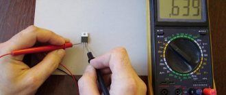
Compound Semiconductor Testing
Such an element in its design resembles a microcircuit. Since it is almost impossible to check the functionality of a microcircuit with a multimeter, it is also impossible to check a composite device using only a tester. For testing you will need to assemble a simple circuit.
It uses a constant voltage source of 10-14 volts. The load of the circuit is a light bulb. An element with a power of 0.25 W is used as a resistor. Its resistance is calculated using the formula h21*U/I, where:
- h21—gain factor;
- U is the voltage of the power supply;
- I is the load current.
To check, a positive signal is supplied to the base from the power source. The light is on. When the polarity is changed, the light goes out. This behavior indicates the performance of the device.
Thus, having learned how to test a transistor with a multimeter, you can easily determine the faulty element in the circuit, even without unsoldering it.
Originally posted 2018-04-06 09:11:12.
No tags for this post.
Defining an Element Type
It’s good if the size of the case allows you to put at least somewhat understandable markings on it. But most often the diodes are so small that it is difficult to mark them even with color. In this case, it is not possible to distinguish a diode from a zener diode, for example, because they are like twin brothers.
Read also: Chainsaw partner 350 where is the breather located
In such situations, only a schematic diagram of the apparatus from which the element was extracted will help. In accordance with it, you can determine the type of component and its brand. If this information is missing, you can try to search for a schematic diagram of the device being repaired on the Internet or take a photograph of the element and also go to the Internet and search by image.
Testing diodes with a multimeter or other tester should only be done after determining their type and brand, because different types are tested differently.
Analyzing the results
When checking diodes (regular and Schottky) with a multimeter, you will get a certain result. Now we need to understand what it could mean. Signs that indicate the health of the semiconductor include the following:
- when connecting a part of the electrical circuit to the device, the latter will output the value of the available direct voltage in this element;
Note! Different types of diodes have different voltage levels, which is why they differ. For example, for germanium products this parameter will be 0.3-0.7 volts
- when connected in the opposite way (the probe of the device to the anode of the product), zero will be recorded.
Reverse check
If these two indicators are met, then the semiconductor is working adequately and the cause of the failure is not in it. But if at least one of the parameters does not correspond, then the element is considered unusable and must be replaced. In addition, it should be borne in mind that it is not a breakdown, but a “leakage” that is possible. This unpleasant defect can appear during long-term use of the device or poor-quality assembly. If there is a short circuit or leakage, the resulting resistance will be quite low. Moreover, the conclusion must be made based on the type of semiconductor. For germanium elements, this indicator in this situation will range from 100 kilo-ohms to 1 mega-ohm, for silicon - thousands of mega-ohms. For rectifier semiconductors, this figure will be many times higher. As you can see, it is not so difficult to assess the performance of semiconductors in any electrical device on your own. The above principle is suitable for testing diode elements of various types and types. The main thing in this situation is to correctly connect the measuring device to the semiconductor and analyze the results obtained.
Checking the photodiode
In a simple test, the reverse and forward resistance of a radio element placed under a light source is measured, after which it is darkened and the procedure is repeated. For more accurate testing, you will need to take the current-voltage characteristic; this can be done using a simple circuit.
An example of a circuit for measuring current-voltage characteristics
To illuminate the photodiode during testing, you can use an incandescent lamp with a power of 60 W or more as a light source or bring the radio component to a chandelier.
Photodiodes sometimes have a characteristic defect, which manifests itself in the form of a chaotic change in current. To detect such a malfunction, it is necessary to connect the element under test as shown in the figure and measure the reverse current for a couple of minutes.
Testing for "creep"
If during testing the current level remains unchanged, then the photodiode can be considered working.
Testing without desoldering.
As practice shows, it is not always possible to test a diode without desoldering it when it is on the board, like other radio components (for example, a transistor, capacitor, thyristor, etc.). This is due to the fact that elements in the circuit may produce an error. Therefore, before checking the diode, it must be desoldered.
Article rating:
Save to:
How to check a zener diode with a multimeter on a board Link to main publication
Related publications
Braun texstyle control 2400 watt how to disassemble
Why do you need to find out?
An LED strip is a device that has a flexible base on which series-connected diodes are placed. This product operates using low voltage (12 or 24 volts).
Note! The most popular are 12 volt tapes. Their main advantage is that they are cheaper than 24 volt products.
Due to the fact that this product is low-voltage, there are difficulties connecting it to a standard 220 volt network. After all, if the connection is made directly, the 12-volt tape will simply burn out. Therefore, to connect LED products of this type, special voltage converters are used - power supplies.
Power supplies for LED strips
The power supply reduces the voltage of 220 volts to the required level - 12 or 24 volts. Today, there is a fairly large selection of converters to power these products, which makes choosing difficult. In order to choose the right power supply, you need to know what current or how many amperes the LED strip used for backlighting will consume. And this is not a constant value, which depends on the following parameters:
- length (how many meters are used). This product can be cut into various lengths. The main thing is that the cutting is carried out in clearly defined places. Otherwise, the tape will be damaged and will not work;
Note! This product is sold in reels. One coil contains five meters of LED.
Place for cutting
- led type;
- LED type;
- density of light sources.
All of the above parameters are necessary in order to calculate the power consumption of the LED strip, namely, what current or how many amperes it can consume.
Miniaturization
With the development of microelectronics, special microcircuits and single-chip microprocessors began to be widely used. All this does not exclude the use of hanging elements. However, if radioelements of conventional sizes are used for this purpose, this will negate the whole idea of miniaturization as a whole. Therefore, open-frame elements were developed - SMD components, which are 10 or more times smaller than conventional parts. The current-voltage characteristics of such components are no different from the current-voltage characteristics of conventional devices, and their reduced dimensions make it possible to use such spare parts in various microassemblies.
SMD components come in several sizes. SMD size 1206 is suitable for manual soldering. They have a size of 3.2 by 1.6 mm, which allows you to solder them yourself. Other SMD elements are more miniature, assembled at the factory with special equipment, and it is impossible to solder them yourself at home.
The operating principle of an smd component is also no different from its large counterpart, and if, for example, we consider the current-voltage characteristic of a diode, then it will be equally suitable for semiconductors of any size. The current range is from 1 to 10 amperes. The markings on the case often consist of a digital code, the decoding of which is given in special tables. They can be tested for suitability using a tester, just like their larger counterparts.