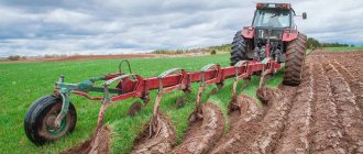
How to make a horse-drawn plow with your own hands will be of interest to anyone who is looking for an adequate option and instructions. Many have tried to make a plow in the likeness of a real horse or tractor plow. But usually such attempts ended in failure. A negative result is not a lack of will and patience, but a lack of skills and knowledge in the field of product geometry.
Design and operation of the plow
The main working parts of the plow are the knife, skimmer and body. If we look at the structure and operation of the plow in more detail, we can add that sometimes an angle bar and a subsoiler are installed on the plow. The auxiliary parts of the plow are a frame with a mounted or trailed device, deepening and deepening mechanisms, support wheels.
The quality of plow work depends on the shape of the body (working surface) formed by the moldboard and ploughshare.
- field board
- sidewalls with heel
- dump
- rack
- ploughshare
The work process consists of cutting off part of the soil from below, lifting it and sending it to the dump. The blade, shifting the layer to the side, partially crumbles it and turns it over, throwing it into the furrow. The layer moves due to the shape of the plowshare-moldboard surface, with the plowshare and mouldboard installed at an angle to the furrow wall and bottom.
Plow bodies differ in the shape of the working surface on
- cultural
- cylindrical rukhadlovye
- screw
- semi screw
- universal
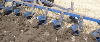
The most common are semi-screw and cultural cases. Good crumbling and wrapping of the formation is ensured by bodies with a cultural surface. Such buildings are used for plowing fallow and virgin lands and old arable soils.
However, in the case of fallow and virgin lands, half-screw bodies are more effective; they wrap the sod layer better, since this type of blade has a wing more bent towards the layer that is being wrapped. When the plow moves, with soil pressure on the body, due to its lateral pressure, the plow tends to move towards the plowed part of the field.
Against this, a field board is attached to each body, to the bottom of the stand, increasing the supporting surface of the plow, which in turn prevents the plow from moving. A plow for non-mouldboard plowing lifts the layer cut by the ploughshare and then it goes to the expander. In this case, the formation crumbles and the soil loosens.
Do-it-yourself plow
The detailed design diagram is that if the soil is mainly made of clay, then it must be processed using small-sized equipment, which is divided into independent units. It looks like this: the plow is placed on one edge of the earth, and the engine is placed on the opposite edge, and they begin to move towards each other.
The plowing cycle is the sequence and change of idle and standard speed in working mode. But this should not be scary, since such a unit has its advantages. The first plus is its compact size. A horse plow can easily fit in the trunk of a car. Secondly, the product weighs little, and any representative of the stronger sex can lift it. You can make a plow yourself, and the materials for making it are freely available and, by the way, are not that expensive. The horse plow is used for:
- plowing;
- cultivation;
- harrowing.
Using a plow, you can easily make recesses under a strip foundation, dig drainage ditches, and perform other construction work.
Plow diagram
The plow is divided into main parts (plow diagram):
- skimmer 1
- Pavilion 2
- knife 4
- frame 3
- support wheel adjustment screw 6
- support wheel 5
- tow hitch 7
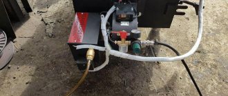
Sometimes a hydropneumatic fuse is installed on plows; this is done for processing old arable soils that are clogged with stones of various shapes and sizes, partially protruding to the surface or hidden in the thickness of the layer. Its main components are: a hydraulic cylinder, a pneumatic hydraulic accumulator (PHA) with a piston and fitting, a valve, a pressure gauge, and oil lines.
Each plow body is controlled by articulated supports and a beam. For better wrapping and crushing of the formation, a chisel, a feather and an angle are installed on the body.
How to adjust a plow for plowing
1. Adjustment of the plow for plowing should begin with its working parts. The main working element of the plow is the ploughshare; when plowing, more than half of the load falls on it. The plowshare must be sharpened accordingly. Otherwise, fuel consumption will increase by 20%, productivity will decrease by almost 20%, and the processing depth may decrease by more than a third.
2. The blades of the plowshares must have attachments with a cutting edge of up to 1 mm, a sharpening angle of 25 - 400. These attachments must be made of hard alloys and of the same size. Deviations should not exceed: blade length 15 mm, back length 10 mm, and width 5 mm. Make sure that all bolt heads are recessed to 1 mm or flush. At the junction of the share and the blade there should be no gap exceeding a millimeter, and the blade itself should not protrude more than two millimeters.
3. It is important that the plowshare and blade are on the same line on the field side. The permissible protrusion of the ploughshare is no more than half a centimeter. It is unacceptable for the body stand to protrude beyond the field edge of the blade and ploughshare. The permissible gaps are: between the stand and the plowshare 3 mm, and between the stand and the blade 6 mm.
4. It is necessary to check the field boards on the plow; they must be level. Their back part should be in the same plane with the edge of the ploughshare. The permissible deviation is no more than half a centimeter.
5.The blade of the ploughshare must be installed parallel to the installation site. Elevation of the rear part is permissible no more than a centimeter. Installation of bent beams and/or skewed frames is not permitted. Otherwise, the correct overall position of the plow body is disrupted. The correct installation of the plowshares can be checked as follows: pull the cord along the heels and toes of the rear and front housings. The permissible deviation of the heels and toes should not exceed plus or minus from the tensioned cord.
Horse plows / Horse plow / Walk with a horse / Russian man plows the land / Horse with a plow
Hot Master Channel
0 fireplace combustion theory https://www.youtube.com/watch?v=yH2B9…
1 chimney for a long-burning stove https://www.youtube.com/watch?v=t2uvR...
2 heat losses in the house https://www.youtube.com/watch?v=QnsoS...
3 standards for a wood stove chimney https://www.youtube.com/watch?v=kafrO...
4 condensate wood poison https://www.youtube.com/watch?v=pKPu3…
5 wood stove rules of use https://www.youtube.com/watch?v=GJHxu…
6 tips and video lessons about building a sauna https://www.youtube.com/playlist?list…
Dear master craftsmen. I welcome you to my channel, those who love to work with their hands and heads!!! This is an exciting activity - a hobby for many people with incomes, as well as a profitable business for those who devote themselves to carpentry, plumbing, furnace and other so-needed household and household chores. Your family will be grateful to YOU for your efforts for the benefit of the family. On my channel, all videos are divided into playlists by topic. Click on the playlists section and you will see their sections. Enjoy watching!!! We bring to your attention. Only videos of our production. our ideas and inventions are useful in production and everyday life. We don’t copy other people’s ideas and don’t shoot about what’s on store shelves. We don’t show you plywood machines and screwdrivers made from snot, and we also don’t suffer from creative impotence. Our unpublished collection contains one and a half hundred unique videos about inventions. useful models of equipment use and homemade products. Which you will someday be able to see on our channels - for now there are two of them. All our developments live a working life in production and are time-tested, bringing us relief in our work, saving time and effort and increasing productivity. On our channel there is a series of videos based on materials from the book of the Hot Master - About household chores and chores. The first book will offer advice with drawings and diagrams on 100 topics, of which 25 super topics will not be shown on the channel. the book will be offered for distribution starting May 2015. We invite publishers to cooperate.
Original link: https://www.youtube.com/watch?v=iH9ukPiOKtE
Plow moldboard and its applications
The moldboard of the plow - its working part of the body is designed to lift a layer of soil that is cut by a ploughshare. The plow moldboard deforms the soil layer, turns the top layer down and dumps it into the furrow. Based on the shape of the working surface, plow moldboards are divided into semi-screw, screw, cultivated and cylindrical.
According to their design, they are divided into composite (two parts), roller, rod, plate, etc. Blades are made of 2 or 3-layer hardened steel. There are plows for plowing speeds of up to 12 km/h (high-speed plowing); they use moldboards with a special shape of the working surface, which ensures good plowing, normal formation turnover and a continuous plowing surface.
How to do it?
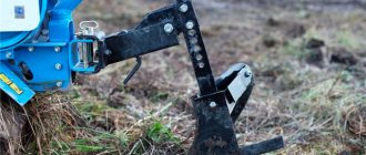
Modern models of walk-behind tractors can be equipped with a reliable plow made by yourself. Varieties of this element: double-turn, reversible, two-body, rotary or Zykov’s product. There are quite a lot of design options. There are even options in which the body is made of a gas cylinder. It’s not difficult to make a high-quality plow for motorcycles yourself if you follow certain rules.
Rotary
The manufacturing of the structure can be divided into several main stages.
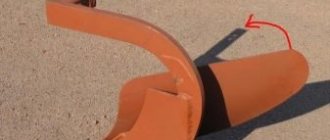
Prepare a good dump in the shape of a cylinder. This must be done exclusively in accordance with the drawing. The part is made of alloy metal
It is important to follow the drawing when making the structure yourself. They put out the ploughshare. The wedges are inserted into the iron sheet (3 mm) at an angle of 45 degrees. Connect the ploughshare to the shield on the side
Be sure to ensure that the blade of the ploughshare is located just below the shield itself (1 cm, no more). Attach the blade to the ploughshare. The working half with the ploughshare is welded to the metal tube, which serves as the base, using a welding machine. On the opposite side - fasteners for motorcycles. When the plow is ready, you can weld an axle with wheels in its lower half.
Turning
The rotating type of plow is rightfully recognized as one of the most functional and practical. This design is an excellent assistant for plowing land on a site, because it can cover a fairly large area. The plow is also good because you don’t have to waste time with it after each approach. You will only need to turn the plow and move in the opposite direction. The productivity of equipment will increase significantly. The main actions are performed in the same way as in the case of a rotary mechanism, but in this case the cutting elements must be below the skid (at least 2 cm).
Disk
It is possible to assemble a disc plow for machinery with your own hands. A similar model is assembled from the following parts:
- disks;
- fist;
- axles;
- bracket;
- scraper;
- drive beam;
- pens;
- screeds.
The disks for the device can be taken from an old “seeder”, if you have one in your arsenal. These elements are installed at an angle to increase work productivity. The hiller is hung on the equipment through the coupling bracket. The T-shaped leash from the plow is screwed to it using bolts and a stopper. At impressive speeds, the hiller may begin to slip, so you will have to work exclusively at low speeds or with twin wheels.
Working parts of the plow
The working parts of plows are cutting or disk knives, skimmers and main bodies.
A disc blade is a disc that rotates on two ball bearings. It is usually installed in front of the rear body, used on general-purpose plows, as well as for soils not clogged with tree roots and stones on bush-marsh plows. A cutting knife is a handle that goes into a knife and is a dihedral wedge. These are used when plowing stone-clogged, soddy soils.
Horse plow: features and manufacturing algorithm
HORSE PLOWS AND HORDERS
PLOWS They are intended for basic tillage with 1 rotation of the layer. Basic tillage is usually the first deepest tillage of the soil after cultivating the previous crop. Such plows come in hanging and trailing types.
HANGING PV-25. used for plowing old arable soils to a depth of 16 cm. The working width is 25 cm. The plow consists of a beam 4 (Fig. 1), a body 1, a cutting knife 3, a harness hook 9, a regulator that includes an arc 5 attached to the end of the beam , a clamping bracket 6 with a bolt and a vertical bar 8, handles 2 and a support wheel 10. It keeps the front end of the beam from turning in the horizontal plane during operation. When plowing, the support wheel, as a rule, is not used, so the front end of the beam seems to hang above the surface of the field, which is why the plow received the name hanging. If the beam is equipped with a support wheel, then the plow is called a semi-forehead plow.
ADJUSTMENT In order to correctly adjust the PV-25 plow and the main position of the harness hook, it is necessary to know the conditions of its equilibrium in the longitudinal-vertical and horizontal planes. In the longitudinal-vertical plane, the center of gravity is at point O (Fig. 2). The projection of the center of gravity to the bottom of the furrow (point 01) is called the trace of the center of gravity. During operation, the plow is acted upon by the force of gravity G and the traction force P. If the force P passes through the trace of the center of gravity, then its vertical component P2 is balanced by a part of the force G, and the horizontal component P1 causes the movement of the plow. In this case, the plow will move steadily, that is, move at a given depth, since there are no moments of force acting on the plow. If the force P is higher than the trace of the center of gravity, for example through point O, then an overturning moment occurs with a shoulder equal to the distance from point O to the bottom of the furrow. The depth of the plow will increase. If a support wheel is installed on the plow, it will be subject to increased load. This will increase the depth of the wheel rut, which means the traction resistance of the plow will increase. If the traction force passes below the center of gravity, then the overturning moment will contribute to the deepening of the plow from the soil. Hence the conclusion is that when the harness hook moves upward, the depth of the plow stroke increases, and downward it decreases. The height of the hook relative to the supporting surface of the body (bottom of the furrow) can be determined by the formula:
(h + a) = (H + a) x 1/(L + 1),
where L is the length of the lines; H—height of the lines on the clamp; a is the specified plowing depth; 1 - distance from the trace of the center of gravity 01 to the hook. In the horizontal plane (Fig. 3), the plow will move steadily, that is, its working width will be constant, with the least traction resistance, if the traction force passes parallel to the wall of the furrow through the trace of the center of gravity. The line of action of gravity G of a single-furrow plow passes through the point determined by the joint line between the plowshare and the moldboard and the longitudinal vertical plane drawn at a distance of 5 cm from the wall of the furrow. The position of the harness hook 9 (Fig. 1) is determined: firstly, by the height of the distance (h + a) (Fig. 2) from the supporting surface of the body (regulated by a vertical bar 8), and secondly, horizontally 5 cm from longitudinal-vertical plane drawn through the field edge of the blade (regulated by clamping bracket 6 with bolt 7).
ADVANCED PP-28. designed for plowing both medium and heavy turfy soils to a depth of 18 cm. Its working width is 28 cm. It is pulled by two horses. One goes along the surface of the field, the other along the bottom of the furrow. ' This plow, unlike the hanging one, has a limber (Fig. 4), on which the front end of the beam rests. The front end has one axle shaft 22 of the field wheel 1 and another of the furrow wheel 3. They can be moved relative to each other using a tension bracket. Attached to the axle shaft of the furrow wheel is a vertical frame 21 with two rows of holes for attaching a transverse bar 19 with a saddle 20. The bar with a saddle can be moved in height and moved to the right or left. To do this, there is a longitudinal slot on the right end of the bar, and a row of holes on the left. A horizontal bar 18 with holes for adjusting the positions of the harness hook 24 is attached to the vertical frame. The frames together with the hook are moved relative to the axle axis of the furrow wheel. The beam 16 is connected to the front end using two chains 4, one of which has a coupling nut 5. The chains are connected by a round link (ring) to the draft of the harness hook, and the ends are connected to the hooks of the cross member 17 of the beam. Chain 23 supports harness hook 24.
INSTALLING THE PLOW TO A SPECIFIED DEPTH To ensure that the furrow wheel does not come into contact with the wall of the furrow during operation, the middle of the saddle 20 of the regulator is installed at a distance of + 5.6 cm (in is the working width of the body) from the vertical plane drawn through the inner edge of the furrow wheel. The plow is placed on a flat horizontal platform so that its body rests on the ploughshare blade and the field board. Then the length of the chains is equalized, and a block equal to the specified plowing depth is placed under the field wheel. The axle shaft of the furrow wheel is installed parallel to the supporting surface, and the draft of the harness hook is installed at an angle of 18.20°. Tension the chains and raise the transverse bar 19 so that the beam rests on the saddle 20. Check the adjustment of the plow by plowing it in the field. At the same time, we must remember that moving the transverse bar with the saddle up reduces the plowing depth, and moving it down increases it. The working width of the plow also depends on the position of the cross bar with the saddle. If you move it to the right, the working width decreases, and if you move it to the left, it increases. After plowing the plow, note the location of the wheel axle shafts relative to each other and the position of the transverse bar with the saddle on the vertical frame. This allows you to quickly restore this adjustment after the plow has passed the first and second furrows. To make the first furrow, the plow body is set to half the specified plowing depth. The field wheel is lowered so that it is in the same plane as the furrow wheel, and the transverse bar with the saddle is lowered by approximately two holes (Fig. 5a). After the first furrow, the plow is adjusted to the second, raising the field wheel to half the specified plowing depth relative to the furrow wheel (Fig. 5b). The body will be immersed in the soil to a specified plowing depth. After making the second furrow, using previously made marks, the initial adjustment of the plow is restored (Fig. 5c). The adjusted plow turns out to be so stable in operation that it almost frees the plowman from controlling it by the handles. Such plows are called “self-propelled”.
Equipment manufacturing methods
A homemade unit can be made in two ways.
- In the first case, a steel pipe is used to make the dump, the diameter of which is 55-60 centimeters and the wall thickness is 0.4-0.5 centimeters. Initially, you need to make a template from thick cardboard. For this purpose, appropriate drawings are used. If you have sheet-bending rollers at hand, then the workpiece can be given the required shape as simply as possible. The blade blank is cut out using scissors. When feeding it to the rollers, an angle of 20 degrees is maintained. After bending it, modification is done using a hammer.
- The second option is a rather labor-intensive way to make the unit yourself. To make it, you need to heat the workpiece in a forge or in any other convenient way. Next, it is bent along the matrix. For this purpose, the blade from the attachments of the T 25 tractor is most often used. Sheet steel is used as a raw material for the production of the body. The next stage involves placing the template on the pipe while maintaining an angle of 20 degrees. The outline of the dump can be drawn using chalk. Next it needs to be cut off. For this purpose, gas welding is most often used. The contour is processed using sandpaper. If the need arises, the blade contour is modified using a hammer.
Manufacturing technology
Initially, the elements of the unit are manufactured from thick cardboard. For this you must also use drawings. In order to make a homemade plow as correctly as possible, it is necessary to maintain the appropriate angles. If the parameters of the unit suit you, then you need to make it out of metal.
After manufacturing the metal elements of the plow, it is necessary to use a steel sheet to assemble them, the thickness of which will be from 2 to 3 millimeters. You need to step back from the edges of the sheet and put a corner on it. In order to make a plow with your own hands, you need to install the plowshare on a metal sheet.
- Correct manufacturing of attachments for the T 25 tractor requires the use of welding to fasten the ploughshare to a metal sheet. Next, you need to place the side shield of the rack under the plowshare. This is done in such a way that it is located in a vertical position and extends beyond the edge of the ploughshare by about 7 centimeters. It also needs to be attached to the metal sheet and plowshare. Welding is most often used for this purpose.
- In order to correctly make a plow for the T 25, it is necessary to fit the moldboard to the ploughshare. It requires maximum tight joining with the canvas. The plowshare blade and the top edge must be at the correct angle. Otherwise, they will need to be finished with a hammer.
- In order to properly manufacture a homemade unit for the T 25, it is necessary to attach the spacer bar to the side shield by welding. If you don't know how to do this, you can watch the video on our website. The shield, plowshare and side sheet must be connected to each other by welding.
The work of a homemade plow
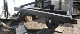
In order for the T 25 plow to independently hold the furrow, a two-wheeled block is fitted to it. The width of the furrow wheel should be 4-5 centimeters, and the diameter should be 32 centimeters. The diameter of the field wheel should be 20 centimeters. The axle for the plow wheels on the T 25 tractor is made from a pipe whose size is ¾ inches.
On one side, the pipe must be bent 90 degrees and a bushing must be welded to it, on which the furrow wheel will later be installed. The field wheel is mounted on the other side of the pipe. The wheel axle is manufactured as a composite one. The pipe itself is attached to the attachment beam by welding.
Setting up the plow
In the video you can see the plow in action (second option)
The depth of soil plowing with a tractor plow ranges from 20 to 24 centimeters. The same distance should be between the field wheel and the toe of the ploughshare. If you provide the ability to move the field wheel vertically, the plow can be adjusted according to the depth of plowing and the width of the soil during work. If you don’t know how to enable wheel movement, then you can watch a video on this on our website.
Making attachments yourself is not very easy, but it is still possible. The main thing is to choose the right material and adhere to the production technology as accurately as possible.
Do It Yourself (Ogonyok) 1996-06, page 65
front plow into the soil:
a - passage of the first furrow;
b - passage of the second furrow;
c - restoration of the initial adjustment of the plow to a given plowing depth
touches the wall of the furrow, the saddle is fixed so that its middle (recess) is at a distance of b + 5.6 cm (b is the grip width of the body) from the inner edge of the furrow wheel.
To do this, the plow is installed on a flat horizontal platform so that the plow body rests on the ploughshare blade and the field board, the length of the chains is equalized, and a block equal to the required plowing depth is placed under the field wheel.
The axle axis of the furrow wheel is oriented parallel to the supporting surface, and the draft of the harness hook is oriented at an angle of 18.20° to the horizontal. Tension the chains and raise the cross bar so that the beam rests on the saddle.
Check the adjustment of the plow by plowing it in the field.
Please note that moving the cross bar with the saddle up reduces the plowing depth, and moving it down increases it. The working width of the plow also depends on the position of the cross bar with the saddle. If you move it to the right, the grip width decreases, and if you move it to the left, it increases.
After plowing the plow, note the location of the wheel axle shafts relative to each other and the position of the transverse bar with the saddle on the vertical frame. This will allow you to quickly restore this adjustment after the plow has passed the first and second furrows for the horse.
To make the first furrow, the plow body is set to a plowing depth equal to half the specified depth. To do this, the field wheel is lowered to the ground so that it is on the same plane as the furrow wheel. At the same time, the transverse bar with the saddle is lowered approximately two holes (Fig. 5, a).
After making the first furrow, the plow is adjusted to the second furrow. To do this, raise the field wheel relative to the furrow wheel to a height equal to half the specified plowing depth (Fig. 5, b). In this case, the plow body will plunge into the soil to the required plowing depth. After making the second furrow, using the marks previously made during plowing, ensure the necessary adjustment of the plow (Fig. 5, c).
The adjusted plow turns out to be so stable in operation that it almost frees the plowman from controlling it by the handles. Therefore, such plows are called “self-propelled”.
REVERSAL PLOW PO-23
The reversible plow (Fig. 6) is designed for smooth plowing, that is, for plowing without breakaway furrows and fall ridges.
About synonyms
Without words of synonyms in texts of various types, be it narration, reasoning, motivation, it is impossible to overcome the unjustified repetition of the same word. Also, the use of synonymous words instead of plowing like a horse is used in literature as a way of connecting adjacent sentences in the text. In the stylistics of Russian literature, when presenting a text in writing, repetition of the same words is identified as a tautology and is a gross lexical error. Thus, when presenting the text at the initial stage, one of the keywords of the synonym is used, and later in the text synonyms that are suitable in meaning are used, revealing and enhancing the theme of the text for a broader presentation.
For example, the original word “plow like a horse” is then, depending on the required applicability, replaced with work.
Do not forget that, in terms of their qualities, synonyms can be applied using the prefix “not” to words of antonyms, words of opposite meaning. At the same time, the lexical meaning of the formed antonym word with a prefix is not also characterized as a synonym.
Horse plow: features and manufacturing algorithm
Plowing is one of the most energy-intensive jobs. The amount of required traction force when plowing depends on the plowing depth, working width, type of soil, its mechanical composition, humidity, degree of weediness, and topography. With normal traction, the horse walks freely, moving the plow smoothly and evenly. If the resistance is high, the horse walks unevenly, sometimes speeding up, sometimes slowing down, making frequent stops. The quality of plowing is greatly reduced. The condition of the plow has a great influence on the amount of required traction force when plowing. A plow, properly adjusted to the appropriate depth and width, moves steadily along the furrow without creating additional resistance. When a plow is correctly assembled, the following basic requirements must be met: the plowshare must be adjacent to a level area with its entire blade; local gaps at the junction of the ploughshare and the blade on the working surface - no more than 1 mm; along the line of the field edge, the blade should not protrude beyond the ploughshare, and the ploughshare can protrude beyond the blade by no more than 5 mm; on the side of the furrow, the edge of the ploughshare can be no more than 10 mm longer than the edge of the blade at the junction; The thickness of the ploughshare blade should not exceed 1 mm. It is necessary that the field board fits tightly to the stand. The rear end of the board and the toe of the ploughshare should be located in the same longitudinal vertical plane. The deviation of the heel of the ploughshare towards the non-plowed field is no more than 5 mm. The skimmer and cutting knife are installed relative to the main body, as shown in Fig. 1. The plowing depth of a hanging plow is adjusted by the height of the harness hook. When plowing shallowly, the harness hook goes lower to the ground, and when plowing deeply, it rises. If the harness hook is stationary or there is no vertical comb, the plowing depth can be adjusted by the length of the lines. The shorter the lines, the shallower the plowing will be. The front plow is adjusted as follows. The first furrow is made by placing the field wheel of the plow at the same level as the furrow wheel, and the saddle of the front frame is lowered 3-4 holes below the working position. In this case, the plow will go deeper to approximately half the normal plowing depth. The second furrow is made by raising the field wheel to half the required depth, with the saddle in the same position. In this case, the ploughshare is buried almost to its full depth. For the third and subsequent furrows, the field wheel is raised from the supporting plane of the body to a height corresponding to the full depth of plowing, and so they continue to work. In this case, the saddle is moved to its normal position if the depth of the second furrow is sufficient; if the depth is insufficient, the saddle is left lowered on the third furrow and only from the fourth furrow is it returned to its normal position. To change the working width (which is done only in exceptional cases), you need to loosen the four nuts of the brackets securing the front frame to the furrow axle, move it to the desired side and tighten the nuts again. The saddle is moved away from the middle position very rarely, for example, when, after prolonged work or careless handling of the plow, the beam becomes skewed relative to the stand. In this case, the plow will deviate to the side during plowing - into the furrow or into the field. If the plow moves into the furrow when the furrow wheel is in the correct position (at the wall of the furrow), the saddle must be moved to the left; if it moves in the field, to the right. Rearrangement of the harness hook along the adjusting arc is carried out when plowing on a slope so that the plow does not slide down, and with different lengths of the arms of the wagon in the double-horse harness. The field wheel can be moved higher or lower so that the front axis is always horizontal both when plowing the first furrow and when plowing to any depth (within the limits of possible depth). When plowing small-contour areas with horse-drawn plows with right-turning bodies, the following methods of movement are used: routing or waddling; circular with loopless one-way turns; penless-circular method (see Fig. 2). The quality of plowing is determined mainly by three main indicators: plowing depth, levelness and ridgeness. Correct adjustment of the plow and selection of horses according to the required traction force on the hook will allow you to avoid overloading the horses, which leads to their rapid fatigue and loss of performance, as well as to carry out plowing in the best agrotechnical terms and with high quality. Note to horse owners. Currently, our industry produces two types of horse-drawn plows: the reversible plow PG-25 and the hanging plow KVP-27A. The first is produced by the Kutaisi Motoblock Plant, the second by the Polotsk Plant of the Ministry of Local Industry of the BSSR. PG-25 is designed for plowing areas located on slopes to a depth of up to 20 cm, and KVP-27A for light and medium soils to a depth of up to 12.5 cm.
G. EGOROV, Art. engineer of the horse technology department at VNIIK
Read it yourself, share it with a friend
| Rice. 1. Diagram of the PP-28 plow in working position.
Horse plow: features and manufacturing algorithm Link to main publication Related publications
|
How to properly set up a plow on a walk-behind tractor? We plow simply, quickly and easily.
Having become the proud owner of a walk-behind tractor of one brand or another, we are faced with the problem of choosing a plow and related elements for plowing our gardens and fields. Spring is a hot time for all people who are not indifferent to the earth, the topic of environmentally friendly nutrition, summer residents and gardeners. How to make work easier, more enjoyable and more useful? This article will discuss how to properly set up a plow, select a hitch, and work on your mistakes. Everything in order:
As a person living in a rural area, I have watched tractors work in the fields since childhood. Plow - what’s so surprising, I thought when I went to buy this attachment for my Agat walk-behind tractor with a 6.5 hp engine. In a specialized store it turned out that not everything is so simple. There are many options for plows, depending on the power of the walk-behind tractor. The choice was made on the advice of the seller, I did not argue, because... there was no point in it. This was followed by the accompanying purchase of a hitch (at that time I imagined it as one whole)
Having installed this attachment on the walk-behind tractor, I rushed on the road with wrenches in my hands for adjustments. We are plowing the land for the first time in our lives—an experimental run. Of course, I consulted with neighbors and acquaintances. Tips in the style: “place the walk-behind tractor on a brick, two fingers under the heel, angle of attack. “All this advice seemed simple, and that’s what frightened me. I had to watch the work of walk-behind tractors when plowing - everyone was sweating, either pushing the walk-behind tractor or running after it - without strength, arms or legs. At first it seemed to me that this is exactly what plowing on a walk-behind tractor looks like. But all this was the result of incorrect plow settings.
I will try to tell you in simple terms and share my experience on the correct setup of the hitch and plow, in which you can easily cope with any volume of plowing on a walk-behind tractor of any brand. The understanding of this came after one season - there is no need to rush anywhere.
First: The plow plows in a position strictly perpendicular to the plane of the ground; we carry out this adjustment after the first and subsequent passes, since the wheel goes into the rut. Everything is simple - as in the photo:
Second: What is the angle of attack? This is how deep the plow will go into the ground before its heel - bottom part takes a position parallel to the line of movement. The greater the angle of attack, the deeper the rut, the larger the blade, the higher the bed))) This is the most common mistake - too large an angle of attack on a light and weak walk-behind tractor - the result is sore hands and back for the one who controlled it. Additionally, you can use weights, but this increases the load on the axle and engine - don’t overdo it, everything is within reasonable limits. In the photo I schematically indicated with lines:
Thirdly: An error in which the walk-behind tractor tends to run either to the left or to the right. If you look at the walk-behind tractor from the top point, the hitch should be in a position strictly perpendicular to the axis of the walk-behind tractor. It’s easy to understand - imagine you are sailing on a boat - how do you steer? You guessed it - everything here follows the same principle. Schematically marked with lines in the photo:
If you follow all these rules for adjusting the plow, then the work will be a joy, the walk-behind tractor will help you, and not be a burden.
But all these adjustments are meaningless if the hitch is of poor quality. And this is the most important mistake! We choose a high-quality, reliable - strong coupling in order to quickly and easily make adjustments, while the reliability of the fastenings should not be questioned while working with the plow.
In the photo, the hitch is black - it has proven itself reliably - the metal is a decent thickness, does not move around in the fastening areas, does not break threaded connections
In the photo, the red hitch is of satisfactory quality - it bends, moves, and the thread on the adjusting pin gets knocked out.