The resistance of any conductor generally depends on temperature. The resistance of metals increases with heating. From the point of view of physics, this is explained by an increase in the amplitude of thermal vibrations of the elements of the crystal lattice and an increase in the resistance of movement to the directed flow of electrons. The resistance of electrolytes and semiconductors decreases when heated - this is explained by other processes.
Deciphering the specifications of a specific model
These were the main parameters of the series, now let’s look at the specification for C831 (see Fig. 5).
B598 Series Model Specification*1
Brief transcript:
- The current value for normal operation, for our part is almost half an ampere, namely 470 mA (0.47 A).
- This parameter indicates the current at which the resistance value begins to change significantly upward. That is, when a current of 970 mA flows through C831, the “protection” of the device is triggered. It should be noted that this parameter is associated with the temperature transition point, since the passing current leads to heating of the element.
- The maximum permissible current value for switching to the “protective” mode, for the C831 is 7 A. Please note that the maximum voltage is indicated in the column, therefore, you can calculate the permissible amount of power dissipation, exceeding which will most likely lead to the destruction of the part.
- The response time for the C831 at a voltage of 265 volts and a current of 7 amperes will be less than 8 seconds.
- The amount of residual current required to maintain the protective mode of the radio component in question is 0.02 A. It follows from this that a power of 5.3 W (Ir x Vmax) is required to maintain the triggered state.
- Device resistance at a temperature of 25°C (3.7 Ohms for our model). Note that by measuring this parameter with a multimeter, checking the posistor for serviceability begins.
- The minimum resistance value for the C831 model is 2.6 Ohms. To complete the picture, we will once again present a graph of the temperature dependence, where the nominal and minimum values of R will be marked (see Fig. 6).
Figure 6. Temperature correlation plot for B59831, RN and Rmin values marked in red
Read also: Make a carport inexpensively
Please note that at the initial stage of heating the radio component, its parameter R decreases slightly, that is, in a certain temperature range, our model begins to exhibit NTS properties. This feature, to one degree or another, is characteristic of all posistors.
- Full model name (we have B59831-C135-A70), this information may be useful for searching for analogues.
Now, knowing the specification, you can move on to testing for functionality.
Marking
There are two ways of marking - alphanumeric and color, in the form of rings and stripes. There are no uniform requirements for letter markings - different manufacturers use their own versions of designations. For example, on a disk thermistor there may be the symbols “15D-30”, which means: nominal resistance 15 Ohms, product diameter 30 mm. Here, the diameter value is directly related to the power dissipation - the larger the diameter, the greater the power dissipation of the thermistor.
Note that another manufacturer may mark these same parameters in a completely different way. Therefore, it is better to use the technical documentation of the product manufacturer.
Where is it used (scope of application)
Thermistors are actively used in various fields closely related to electronics. They are especially important when implementing processes that depend on the correct temperature settings.
This approach is relevant for computer technologies, information transmission devices, high-precision industrial equipment, etc.
A common way to use thermistors is to limit the currents that arise during the startup of devices.
When voltage is applied to the power supply, the capacitor quickly gains capacity, which leads to increased current flow. If you do not limit this parameter, there is a high risk of damage (breakdown) to the diode bridge.
To protect an expensive component, a thermistor is used - an element that limits the current in case of sudden heating. After the mode is normalized, the temperature drops to a safe level and the thermistor resistance returns to its original level.
How to determine the health of SMD resistors
SMD resistors are surface-mount components, the main difference of which is the absence of holes in the board. The components are installed on the current-carrying contacts of the printed circuit board. The advantage of SMD components is their small dimensions , which makes it possible to reduce the weight and size of printed circuit boards.
Testing SMD resistors with a multimeter becomes more difficult due to the small size of the components and their labels. The resistance value on SMD components is indicated as a code in special tables, for example, the designation 100 or 10R0 corresponds to 10 Ohms, 102 indicates 1 kOhm. Four-digit designations may occur, for example 7920, where 792 is the value and 0 is the multiplier, which corresponds to 792 ohms.
A surface mount resistor can be checked with a multimeter by completely desoldering it from the circuit, leaving one end soldered on the board and lifting the other with tweezers. After this, a measurement is carried out.
Problems with temperature control on your unit may indicate problems with the thermostat, the resistance of which can be checked using a multimeter.
Read also: Design and principle of operation of centrifugal pumps
I connected and set up this multimeter according to the instructions and turned the knob to the lowest ohms range. The working thermostat shows a resistance of zero or close to zero. This thermostat has a reading of 1.4, which means it is working. If there are no readings on the device, then the thermostat is faulty and needs to be replaced.
A posistor is one of the parts of the system that is responsible for demagnetization. With high magnetization, the TV image is distorted or stripes appear. Their appearance means that the device has failed. It is necessary to check its functionality. If necessary, the posistor is repaired or replaced.
Types by operating principle
Thermistors differ in their operating principle. There are two types:
- CONTACT. This category includes thermocouples, temperature sensors, filled thermometers and bimetallic type thermometers.
- CONTACTLESS. This group includes thermistors built on the infrared operating principle. They are actively used in the defense sector due to their ability to detect thermal radiation from infrared and optical rays (emitted by gases and liquids).
What pharmacist malfunctions can you encounter?
You can determine if there is a fault in an element by seeing a distorted image on the screen. This means that the element is highly magnetized. This problem can be resolved by connecting the grid in series with the device. The mesh is the outer loop that covers the inside surface of the screen.
Read also: Malfunction of the charger for the screwdriver
A posistor is often soldered to the screen. Therefore, it becomes very difficult to check it without disconnecting it from the TV. To take measurements, you need to unsolder at least one part of the device from the grid. But the best solution would be to completely remove the device from the system.
You can heat the posistor with a simple hairdryer. To check the functionality of the device without heating it externally, you need to assemble an electrical circuit. This will help determine the device type. The instructions should state at what voltage the element operates and what temperature it can withstand.
You can determine if the device is working properly by heating it with a hairdryer. If an increase in resistance is noticed, then the element is working. But this method of verification has a drawback - the results may be erroneous. The problem is that the resistance of the parts of the assembled circuit can change over time, and therefore they begin to work unstable.
Another way to determine a posistor malfunction is image distortion. It may ripple, or extra stripes may appear. You can determine the performance of the element using a multimeter. It is recommended that the posistor be cold, since resistance increases when heated.
Another problem is that the contacts have fallen off. With constant heating of the posistor, they begin to wear out, and as a result they fall off. The contacts may look normal on the outside but not work. You can determine their performance using an ohmmeter.
If the posistor is broken or shorted, the fuse will blow the first time you turn on the TV. If there is no short circuit in the network, you need to disconnect the posistor and check its functionality.
Attention! It is possible that it is not the posistor itself that is damaged, but the element responsible for cooling it. We are checking.
Types and design of thermistors
Thermistors can be divided into two large groups according to their response to temperature changes:
- if the resistance drops when heated, such thermistors are called NTC thermistors (negative temperature coefficient of resistance);
- if the resistance increases when heated, then the thermistor has a positive TCS (PTC characteristic) - such elements are also called posistors .
The type of thermistor is determined by the properties of the materials from which the thermistors are made. When heated, metals increase resistance, therefore, based on them (more precisely, on the basis of metal oxides), thermal resistances with positive TCR are produced. For semiconductors, the relationship is the opposite, which is why NTC elements are made from them. Thermally dependent elements with negative TCR can theoretically be made on the basis of electrolytes, but this option is extremely inconvenient in practice. His niche is laboratory research.
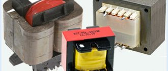
The design of thermistors can be different. They are produced in the form of cylinders, beads, washers, etc. with two terminals (like a regular resistor). You can choose the most convenient form for installation at your workplace.
Step-by-step instructions for checking a posistor with a multimeter
For the testing process, in addition to the measuring device, you will need a soldering iron. Having prepared everything you need, we begin to act in the following order:
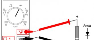
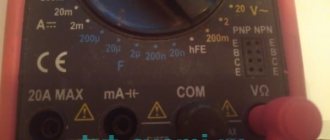
- We connect the part under test to the multimeter. It is advisable that the device be equipped with “crocodiles”; otherwise, we solder a wire to the terminals of the element and wind it onto different probe needles.
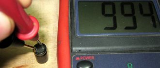
- We turn on the measurement mode of the least resistance (200 Ohms). The device will show the nominal value of R, characteristic of the model being tested (usually less than one to two tens of ohms). If the reading differs from the specification (taking into account the error), it can be stated that the radio component is faulty.
- We carefully heat the body of the tested part using a soldering iron, the R value will begin to increase sharply. If it remains unchanged, the element must be changed.
- We disconnect the multimeter from the part being tested, let it cool, and then repeat the steps described in steps 1 and 2. If the resistance has returned to the nominal value, then the radio component can most likely be considered serviceable.
Date: 09.12.2015 //
Thermistors are divided into two types: posistors and thermistors . They all change their resistance depending on their temperature. For posistors, the resistance increases depending on temperature, while for thermistors, on the contrary, it decreases . Thermistors find their application in many components of various equipment and equipment, ranging from temperature sensors to inrush current limiters in energy-saving lamps, power supplies or motors.
Where is it located on the diagram
The display of the thermistor on the diagram may vary. The product can be easily found by the designations t and t0. Externally, it is reflected as a resistance through which a strip passes diagonally with a “stand” under t0 from below. The main designations are R1, TH1 or RK1.
If in doubt about the scope of application, the thermistor can be heated and its behavior observed. If the resistance changes, this is the required element.
Thermistors are used almost everywhere - in the charger board, in car amplifiers, PC power supplies, in Li-Ion batteries and other devices. It is not difficult to find them on the diagram.
Graphic designation
In UGO thermistor diagrams, the thermistors may differ slightly, but the main sign of thermal resistance is the symbol t next to the rectangle symbolizing the resistor. Without this symbol, it is impossible to determine what the resistance depends on - for example, varistors have similar UGO (resistance is determined by the applied voltage) and other elements.
Sometimes an additional designation is applied to the UGO, which determines the category of the thermistor:
- NTC for elements with negative TCS;
- PTC for posistors.
This characteristic is sometimes indicated by arrows:
- unidirectional for PTC;
- multi-directional for NTC.
The letter designation can be different - R, RK, TH, etc.
