Verification steps
Checking diodes with a multimeter
Diodes operate at low DC voltage. It is generated by blocks that are difficult to connect to. But part of the LED design is a semiconductor junction, due to which current is passed in a given direction. If there is enough current, the light bulb lights up.
Using a multimeter, it is easy to determine the health of the element. To do this, set the device to dialing mode, after which:
- The probes are thrown onto the area of the semiconductor that needs to be checked.
- The red probe with a positive charge is connected to the LED anode.
- A black probe with a negative charge is thrown onto the cathode.
- The device screen should display an indicator of the voltage drop after the pn transition.
- The polarity of the connection changes. If there is no voltage drop, the diode is operational.
If the multimeter does not have a “Ring” mode, set it to 1 Ohm with the switch.
Specifications
When purchasing an LED lamp, you may need to purchase a driver if the lighting device does not have a current converter.
Main characteristics:
- output current, A;
- operating power, W;
- output voltage, V.
The output voltage may vary. It depends on the power connection diagram and the number of LEDs. The brightness level and power depend on the current value.
To ensure that the diodes shine brightly and do not dim, the current at the driver output is maintained at a given level. The power of the converter should be slightly higher than the total number of W of all diodes.
To calculate the driver power, use the formula: P = P (led) × X where:
- P (led) is the power of one LED;
- X – number of diodes.
If the calculated power is 10 W, the driver must be taken with a margin of 20-30%.
LED strip testing procedure
Each section from one point (plus and minus) to another is checked for integrity or breakage.
It is problematic to check the LED strip with a multi-meter, since it does not glow. Weak light occurs when testing in Hfe mode. Testing is also complicated by burnouts not of the diodes themselves, but of the contact tracks or current-carrying sections. To find out about a problem:
- Find conditional identical segments of 3 LEDs along the border of the contacts and the transverse strip.
- Touch the probes to each area in turn, applying current to the power contacts.
- Ring the power supply - it fails due to load drop.
Checking the resistance will provide a complete picture of the integrity of the LEDs.
The main causes of malfunction and failure of LEDs
A feature of any emitting diode is its low reverse voltage limit, which is only a few volts higher than the drop across it in the open state. Any electrostatic discharge or incorrect connection during circuit adjustment can cause the LED (abbreviation for Light-emitting diode) to fail. Ultra-bright, low-current LEDs, used as power indicators for various devices, often burn out as a result of power surges. Their planar counterparts (SMD LEDs) are widely used in 12V and 220V lamps, strips and flashlights. You can also verify their serviceability using a tester.
It is worth noting that a small proportion of defective LEDs (about 2%) are supplied from the manufacturer. Therefore, additional checking of the LED with a tester before mounting it on a printed circuit board will not hurt.
Features of checking LED light bulbs
Using a multimeter, you can test color, standard and super-bright diodes.
Standard light bulb with E27 base
Checking an LED lamp
A similar lamp is used for household chandeliers or lamps. To check whether an LED is working or not working, you will need:
- Remove the diffuser from the light bulb using a plastic bank card placed between the element and the body.
- Carefully move the plastic card along the glue. A durable seam can be heated with a hair dryer.
- Open the board.
- Touch the elements with probes and wait until they glow with a dim glow.
If the diodes do not light, the light bulb is broken.
Super bright diodes
Checking a powerful diode
A garland is usually equipped with blue, yellow or white LEDs. The test is carried out without probes using transistor sockets according to the following algorithm:
- Determine the pinout of the SMD.
- Find 8 sockets at the bottom of the device - 4 left ones for PNP transistors and 4 right ones for NPN transistors.
- Place the probes by inserting the anode into hole E and the cathode into hole C.
- Open the PNP element by applying a positive charge to the emitter E. A working LED will light up.
- Change the polarity of transistors for NPN. The anode is placed on C, the cathode - on E.
Transistor sockets are useful for testing diodes with long contacts without solder.
Super bright
Testing yellow, blue and white LEDs used as lighting sources and called super-bright LEDs is not particularly difficult. To do this, it is enough to connect the element’s terminals to a power source with a voltage of 3 to 4.2 V (no more!).
As such a source, it is most convenient to use a pair of one-and-a-half-volt batteries connected in series. But the fact of the matter is that they are not always at hand.
Is it possible to carry out the test using a conventional multimeter, which every radio amateur has, especially since modern versions of this device provide a special mode for checking diodes?
It turns out there is such a possibility. Although the mentioned mode, due to insufficient power supply, will not help in this case. Instead, we will use the mode for measuring transistor parameters , which is also provided in every modern digital multimeter model.
To study transistors, the tester is equipped with a special connector to which the element leads are connected. It is labeled with the letters PHP. The cathode of the ultra-bright LED (this is the shortest pin) must be connected instead of the collector (position “C” on the connector), and the anode - instead of the emitter (position “E”). If the element is valid, it will begin to glow, and the position of the measurement mode switch in this case does not matter.
In most cases, the lighting element is part of the LED circuit and it will not be possible to plug it directly into the PHP connector without unsoldering. It is not possible to check it using probes, since they cannot be connected to the connector.
The problem can be solved by making a simple design consisting of an adapter and probes connected to it from an old or broken multimeter.
How to make probes with an adapter for a PHP connector
We need very little:
- two unnecessary probes (the plugs must be cut off);
- a small fragment of double-sided textolite;
- a pair of metal clips;
- SMD LED (necessary for ease of use, but the device will work without it).
A paper clip should be soldered to the textolite plate on each side, having first bent their ends 180 degrees. The result will be something like an electric plug.
The thickness of the PCB fragment should be such that the distance between the pins of the “plug” corresponds to the distance between the inputs “C” and “E” on the PHP connector. That's all, the adapter is ready. All that remains is to solder the wires from the probes to it (again on both sides).
It is better to place the textolite between the paper clips asymmetrically. This will make it easier to understand which side the adapter should be plugged into the transistor connector of the multimeter, so as not to confuse the polarity.
The design can be supplemented with an SMD type LED, which will serve as an indicator.
How to make a dipstick with your own hands
If you don't have standard probes to sacrifice, you can use homemade ones instead. To make them you will need:
- a pair of needles;
- tinned wire with a diameter of 0.2 mm (removed from a stranded wire).
The wire should be wound around the needle so that its turns fit snugly against each other, and then soldered. It is very convenient to use nickel-plated needles for this purpose , then soldering is done as easily and quickly as possible. Often such a probe provides better contact than a standard one.
How to check an LED spotlight
Internal structure of the spotlight
The LED is checked after determining the type of element. The following are installed on the lanterns:
- a board with small SMDs, which are checked by continuity in the same way as a standard light bulb;
- a large yellow element operating on a voltage of 10-30 V.
The voltage of a large element is high for the tester, so the operability of the element can only be determined by the driver. It must match the performance of the diode.
Diagnostics of the LED in the flashlight
An LED flashlight, battery-powered or other types, is a fairly reliable device, but it is not immune to breakdowns. If, even after installing new batteries, the glow remains weak or completely absent, you need to check the functionality of the LEDs and their drivers.
Before diagnosing a flashlight, it would be a good idea to check the batteries (even if they have just been unpacked) on some known good device. This advice may seem trivial to some, but quite often, as practice has shown, the cause of “showdowns” with household electronics is defective batteries, which is the last thing the home craftsman realizes.
Checking the flashlight is carried out in the following sequence:
- Unscrew the cap or conical part at the front of the housing.
- We remove the LED module.
- There are two contact pads on the LED board, to which the red and black wires are connected. The red wire corresponds to the positive polarity (marked “+” on the board), and the black wire corresponds to the negative polarity (marked “-”). In accordance with the polarity, a voltage of 3–4 V (no more than 4.2 V!) should be briefly applied to the contacts. If the brightness of the LED has not changed, then it needs to be replaced. Otherwise (the LED lights up properly), the driver must be replaced.
- Replacing an LED is only possible if its board is attached to the LED module capsule with screws. If the board is mounted on hot-melt adhesive, replacement will be impractical; in this case, the entire module is replaced.
After unscrewing the board, unsolder the LED and then install a new one.
In flashlights, LEDs are installed on aluminum radiators. To ensure effective heat dissipation, a fresh coat of special heat-conducting paste, also called thermal paste, should be applied to the heatsink before installing a new LED. The old dried layer, even if quite thick, cannot be reused and must be removed.
The test of a separate LED and the simplicity of the tester’s design are clearly demonstrated in the following video from the largest supplier of electrical equipment in Russia.
Often, when one or another electronic device breaks down, we without hesitation take the victim to repair, where we are presented with a hefty bill. Meanwhile, the cause of the accident may simply be a failure of the LED, which can easily be replaced on your own.
Thus, the ability to check the performance of these elements, which are used quite widely today, will save money and reduce repair time to a minimum.
LED lamps are popular and have many advantages, but their complex design means that the location of the breakdown is not always obvious. Checking the LEDs for functionality, if they break down, allows you to determine the cause of the malfunction and decide the fate of the problematic device. Let's look at how you can find out the condition of lamps at home using a standard tester.
Nuances of testing infrared diodes
Testing an Infrared LED
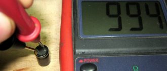
The infrared LED produces invisible radiation, so it is important to monitor the readings on the multimeter display. The probes are installed by applying plus to the anode and minus to the cathode. By touching the probes to the working IR diode, you can see the number 1000 on the screen. When the polarity is changed, 1 is displayed.
To accurately check the infrared diode with transistor sockets, a smartphone camera or digital device is used. The IR LED will need to be placed in the transistor sockets and the camera pointed at it. Serviceability is indicated by a glowing blurry spot on the gadget’s display.
Soldering a parallel red LED glow will clearly reflect the performance of the diode. If a signal is supplied to the element at the moment of flickering, it should be replaced. If the backlight does not work, the remote control is faulty.
Concept of voltage drop (operating)
A light-emitting diode (aka LED) has one important characteristic - operating voltage or drop voltage. This value shows how many volts the voltage will decrease when passing through the LED in a series connection.
For understanding, it’s worth giving a small step-by-step example:
- The diode has a drop of 3.4 V, and the supply voltage is 12 V.
- After powering the first diode, 8.6 V will remain from 12 V (12-3.4 = 8.6).
- On the second, another 3.4 V will be lost, and 5.2 V will remain (8.6-3.4 = 5.2).
- After the third we get 1.8 V (5.2-3.4 = 1.8).
The final value is less than the voltage drop of the light-emitting diode, which means that it will not be possible to power more of them.
The operating voltage is influenced by the material from which the LED is made. According to operating voltage they are divided into:
- LED with voltage from 3 V to 3.8 V: blue, white, blue-green.
- LED with voltage from 1.8 V to 2.1 V: red, yellow, orange, green.
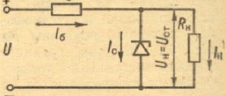
Checking the LED Bridge
Checking the diode bridge
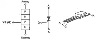
The diode bridge is an assembly of 4 elements. They are connected so that AC voltage is supplied to two of the 4 terminals, turns into DC voltage and is removed from the other 2 terminals. Zener diodes equalize voltage within a narrow range.
You can ring the LED bridge like this:
- Find which pin to connect the multimeter to by making a conditional numbering.
- Ring the first diode by placing probes on pins 1 and 2.
- Test the second LED by connecting probes to pins 2 and 3.
- Measure the parameters of the third diode by connecting probes to pins 1 and 4.
- Determine the serviceability of the fourth element by placing probes on pins 4 and 3.
- View the readings on the scoreboard.
Voltage stability is checked in the maximum range mode - 220 V. It is increased gradually and stopped supplying until current flows through the circuit.
You will need to place the black probe on the anode, the red one on the cathode, and then connect the anode to the current limiting resistor, and the cathode to the power source.
How to choose a driver for an LED lamp?
When connected to a current stabilizer, the semiconductors receive the power they need and achieve their rated characteristics. The service life of the diodes depends on how correctly the driver is selected.
What parameters to pay attention to:
- Power. It determines the maximum permissible load for which the device is designed. For example, the marking (20x26)x1W means that from 20 to 26 LEDs, each with a power of 1 W, can be connected to the driver simultaneously.
- Current and voltage (nominal values). Manufacturers indicate this parameter on each LED, and it is according to this parameter that the driver is selected. If the maximum rated current is 350 mA, it is necessary to connect a power supply of 300-330 mA. This range of operating currents makes it possible to ensure the shelf life of the lamp as specified by the manufacturer.
- Protection class. This indicator determines where exactly the lamps can be used - outdoors or indoors. The moisture resistance and tightness class is indicated by the letters IP and expressed in two numbers. The first number indicates protection from solid fractions (dust, dirt, sand, ice), the second – from liquid media. The protection class does not indicate the temperature at which the luminaire can be used.
- Frame. The driver may have an open perforated metal case or a closed one. In the second case, the device is placed in a metal box. An unsealed plastic case is suitable for home use.
- Principle of operation. A limiting resistor does not eliminate voltage surges in the electrical network and does not protect against impulse noise. The slightest change in voltage leads to sudden jumps in current. Linear stabilizers are considered unreliable and low-efficiency drivers; preference is given to switching circuits.
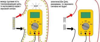
Specifics of the dialing mode
Symbols on the multimeter panel
A multimeter is a universal tester that can be used to test light-emitting diodes and other elements. During operation, the device makes a squeaking or ringing sound, which is why the mode is called ringing.
Operating a multimeter in dialing mode has several features:
- the switch is placed to check the diodes, the probes are thrown onto the contacts;
- the polarity of the terminals is determined, but if it could not be detected, the LED light source will not fail;
- when the probes are correctly connected to the contacts and the correct polarity, the working diode will light up;
- during the dialing process, no current with a large value is supplied, so the backlight of the diodes is visible only in a darkened room;
- if there are difficulties with dimming the lighting, look at the device display - the indicator of the working SMD is different from 1;
- high-power LEDs without desoldering are tested after adding adapters.
Before starting work in ringing mode, determine the anode and cathode of the light source being tested.
Main conclusions
It is not difficult to check LEDs with a multimeter if you understand the principle of their operation. The main task is to prepare the conditions, modify the probes or make special contacts. The correct polarity plays an important role, changing which will not allow even a working element to glow. The process does not take much time; preparation, dismantling or disassembling of devices takes longer. The general principle is to apply the appropriate voltage to the problem element, from which it should light up if it is in working condition. If the glow is not observed even when the polarity is changed, it means that the LED (or section of the strip) is faulty and must be replaced.
Read also: Drawing of a wooden knife with dimensions
Testing an LED with a multimeter is the easiest and most correct way to determine its performance. A digital multimeter (tester) is a multifunctional measuring instrument, the capabilities of which are reflected in the switch positions on the front panel. LEDs are checked for functionality using functions present in any tester. Let's look at the testing methods using the DT9208A digital multimeter as an example. But first, let’s touch a little on the topic of the reasons for the malfunction of new light-emitting diodes and the failure of old ones.
Checking LEDs without desoldering
Probes for a multimeter with adapters
You can check an LED lamp without desoldering its diode elements. You will need an adapter, which you can make yourself from paper clips, individual wire strands, pieces of sewing needles, and twisted pair wiring. The selected product is soldered to the meter probes. A PCB gasket is made between the parts of the adapter, and then the entire structure is wrapped with insulating tape.
Multimeter probes with an adapter are connected to the contacts of a light-emitting diode or to PNP blocks. Testing is carried out sequentially for each element.
Checking the functionality of light-emitting diodes in a flashlight
Testing the LED flashlight board
Testing a standard flashlight is a clear example of work for which you do not need to solder the elements. To find out if the LED sources are working, you need to:
- Disassemble the flashlight and remove the board with LEDs from it.
- Without removing the solder, place the probes on the contacts of the PNP connector, observing the polarity.
- Set the switch to dial.
- Look at the scoreboard and the lights.
- Determine whether the circuit is working properly by checking its resistance. A resistance value of zero when connected in parallel indicates a malfunction of one LED.
Test each diode separately.
How to ring without soldering
To check the LED without desoldering, you need to analyze the device circuit. If there are no circuits parallel to the diode, you can ring it without desoldering it. Parallel circuits may influence the result.
You need to solder sharp steel needles onto the multimeter probes. The entire needle except the tip and probe must be insulated, for example, with heat-shrinkable tubing. Using a probe with a needle, pierce the layer of protective varnish until it comes into contact with the diode terminal on the case or the contact pad on the board. Measuring resistance in the forward and reverse directions shows the performance of the device. Direct resistance is tens to hundreds of Ohms. The opposite is hundreds of kiloohms or more.
Available materials for testing
In addition to a multimeter, a lamp, flashlight or LED spotlight can be checked:
- Battery. A CR2032 battery is suitable for the computer motherboard. Its voltage of 3 V is enough for all types of diodes.
- A 4.5 and 9 V battery together with a ballast resistor. It will give a voltage drop to a safe value. 750 Ohms are supplied to the Krona, and from 150 to 200 Ohms to 4.5 V products.
- Battery from a radio bell or remote control. An LED strip is tested with a 12 V element. Its contacts are thrown onto the poles, after which points with burnt-out LEDs are found. Connectors are tested in the same way.
- A special LED tester operating on the basis of AA batteries with a parallel connection.
- An old charger from which the plug on the phone is removed and the contact is protected. The red wire will be positive and will go to the anode. Black is used as a minus and is connected to the cathode. If there is enough voltage, the LED lights up.
Testing a UV diode is complicated by its sensitivity to high voltage. It is supplied with a nominal value of no more than 3.4-4 V.
Connection
Connecting the driver to LEDs does not cause any difficulties for users, since its body has the necessary markings.
How to connect the driver:
- Apply input voltage to the input wires (INPUT).
- Connect LEDs to the output wires (OUTPUT).
When connecting, observe the polarity:
- Polar input (INPUT). If the driver is powered by constant voltage, then connect the “+” pin to the same pole of the power source. If the voltage is alternating, pay attention to the markings on the input wires. There are two options: “L” and “N”. Apply a phase to the “L” terminal (find it using an indicator screwdriver), and a zero to the “N” terminal.
- “~”, “AC” or no markings – you don’t have to observe the polarity.
There is a second option for connecting LEDs - several chains containing an equal number of diodes are connected in parallel. When connected in series, all elements glow equally; when connected in parallel, the lines can have different brightnesses.
Tips and tricks
When diagnosing LED devices, the following factors must be taken into account:
- if the voltage rating is at the limit, and the luminous flux does not appear, you can briefly increase the current;
- when high power is supplied, the LED source heats up;
- the normal heating temperature of the diode is from 70 to 75 degrees (do not burn your palm when touched);
- using a battery, you can additionally set the diode connection resistance;
- if the polarity is changed, even a working element will not have a backlight;
- the optimal material for a homemade probe is nickel-plated needles, which are easy and quick to solder;
- A working IR LED lights up when the radiation is directed at the sensitive area.
Testing LED light sources is easy if you know how to use a multimeter. The user needs to prepare the conditions for testing - select the polarity, design probes or adapters, make special contacts.
Types of drivers
All drivers are distinguished according to three criteria - the method of stabilization, design features and the presence/absence of protection. Let's consider all the options in more detail.
Linear and pulse
Depending on the current stabilization circuit, drivers are divided into two types - linear and pulsed. They differ in operating principle and efficiency.
The electronic driver circuit is tasked with ensuring stable values of current and voltage supplied to the crystal (LED). The simplest and cheapest option is to include a limiting resistor in the circuit.
Linear power circuit:
This elementary circuit is not capable of automatically maintaining current. As the voltage increases, it increases proportionally and, when it exceeds the permissible value, the crystal will collapse from overheating.
More complex control is carried out by connecting a transistor to the circuit. The disadvantage of a linear circuit is that the power decreases as the voltage increases. This option is acceptable when operating low-power LED sources, but when operating high-power LEDs, such circuits are not used.
Advantages of a linear circuit:
- simplicity;
- cheapness;
- relative reliability.
Along with linear circuits, current and voltage can be stabilized by pulse stabilization:
- after pressing the button, the capacitor is charged;
- after being released, the capacitor discharges, releasing the stored energy to the semiconductor element (LED), which begins to emit light;
- if the voltage increases, the charging time of the capacitor decreases; if it decreases, it increases.
The user does not have to press a button - the electronics do everything for him. The role of the push-button mechanism in modern power supplies is performed by semiconductors - thyristors or transistors.
The considered operating principle is called pulse width modulation in electronics. Tens and even thousands of operations can occur per second. The efficiency of such a scheme reaches 95%.
Simplified pulse stabilization scheme:
Electronic, dimmable and capacitor-based
The scope of its application and performance characteristics depend on the principle of the driver design.
Types of drivers by device principle:
- Electronic. Their circuits necessarily use a transistor. A capacitor is installed at the output, eliminating or at least smoothing out current ripples. Electronic converters are capable of stabilizing currents up to 750 mA. Electronic drivers fight not only ripples, but also electromagnetic high-frequency interference induced by electrical appliances (radio, TV, router, etc.). The presence of a special ceramic capacitor allows you to minimize interference. The downside of the electronic driver is its high cost, but the plus is that the efficiency is close to 95%. They are used in powerful LED lamps: car headlights, floodlights, street lamps.
- Dimmable. A special feature of dimmable drivers is the ability to control the brightness of the lamp. The adjustment is based on a change in the output current, which determines the brightness of the light flux. The driver can be included in the circuit in two ways: between the lamp and the stabilizer or between the power source and the converter.
- Based on capacitors. These are inexpensive models used for budget LED lamps. If the manufacturer did not provide a smoothing capacitor in the circuit, then ripple is observed at the output. Another disadvantage is insufficient security. The advantage of such models is their high efficiency, tending to 100%, and the simplicity of the circuit. Such drivers are easy to assemble with your own hands.
Capacitor drivers may cause flicker and are not recommended for use with indoor applications. Flickering has a harmful effect on vision and irritates the nervous system.
With or without housing
The driver may or may not be located inside a protective housing. Electronic circuits are vulnerable to many external factors, so placing the driver in a housing is considered a more reliable option.
The housing protects the electronic converter from moisture, dust, direct sunlight, etc. Unframed models are cheaper, but they have a shorter service life and worse operating stability. They are more suitable for hidden installation.
Is it possible to check with a battery?
You can check the diode without a tester by using a Krona battery (9 volts) or several finger batteries connected to each other. Checking super-bright (yellow, white, blue) diodes is a simple procedure. It is enough to connect a power supply of more than 3 volts to the terminals of such an element - 4.2 volts.
A 3 volt battery (or 2 pieces of 1.5 volt each) can be used as power when checking functionality. White and blue LEDs are tested without using a resistor (it limits the current). For yellow and red, you need a 60-70 Ohm resistor. It is best to use a discharged coin-cell battery. For example, from electronic floor scales.
Examination:
- Tape 1 needle from a disposable syringe to the battery with tape on one and the other flat side.
- Check the functionality of the diodes.
How many volts are there?
The operating voltage of an LED can be determined not only by its appearance and characteristics, but also by the color glow of the LED. To do this, check out the table below.
| LED color | Voltage, V |
| Red | 1,63 ― 2,03 |
| Yellow | 2,1 ― 2,18 |
| Green | 1,9 ― 4,0 |
| Blue | 2,48 ― 3,7 |
| Orange | 2,03 ― 2,1 |
| Infrared | up to 1.9 |
| Violet | 2,76 ― 4 |
| White | 3,5 |
| UV | 3,1 ― 4,4 |
How color affects brightness
To understand this aspect, you need to know what happens inside the diode and what affects the color type.
The internal structure of a semiconductor LED consists of two semiconductors designed for different levels of conductivity. An electric current passes through the first semiconductor due to a physical phenomenon that ensures the movement of free electrons. Current moves through the second conductor due to the movement of “holes”.
A “hole” is a place where an electron is missing.
At the junction of semiconductors, the stage of recombination of “holes” and electrons begins. An electron flies to the place of the “hole”, which makes the atom neutral - a photon is emitted, that is, color appears.
Color can change if it is influenced by the following factors:
- what type of semiconductor the LED was made from;
- what impurities were used at the points of contact between two semiconductors;
- width of the forbidden zone (recombination site);
- parameters and magnitude that influence the current strength in a section of the electrical circuit.
The color change occurs due to an increase or decrease in electrical current. When referring to Ohm's law, it must be remembered that the higher the voltage, the greater the current. This means that the photon's energy will also increase, thereby moving towards a cooler (blue) and brighter glow.
LED lamp voltage
Modern LED lamps, manufactured for home use and industrial purposes, are designed for an alternating supply voltage of 110 - 220 V. This figure is achieved by combining several chips. In this case, the driver built into each lamp is responsible for lowering the voltage and obtaining a constant current.
The LEDs themselves in the lamp are designed for a lower DC voltage. Most lamps use SMD 5050 or SMD 2835 LEDs. Chinese Corn lamps use SMD 3014 LEDs. All these LEDs are designed for an operating voltage of 2-3.2 V (DC), the more accurate value depends on the emitted color, the voltage drop also Everyone is different, from 1.8 V to 3 V.