Checking wirewound and non-wire resistors. To check wire and non-wire resistors of constant and variable resistance, you must do the following:
- carry out an external inspection;
- check the operation of the driving mechanism of the variable resistor and the condition of its parts;
- using the markings and dimensions, determine the nominal resistance value, permissible dissipation power and accuracy class using an ohmmeter, measure the actual resistance value and determine the deviation from the nominal value;
- For variable resistors, also measure the smoothness of the change in resistance when the slider moves.
The resistor is in good condition if there is no mechanical damage, the value of its resistance is within the acceptable limits of the given class, and the contact of the slider with the conductive layer is constant and reliable.
Checking all types of capacitors
Electrical faults include: breakdown of capacitors; short circuit of the plates, change in the nominal capacity beyond the tolerance due to aging of the dielectric, exposure to moisture, overheating, deformation; increase in leakage current due to deterioration of insulation.
Complete or partial loss of capacity of electrolytic capacitors occurs as a result of drying out of the electrolyte.
The simplest way to check the serviceability of a capacitor is an external inspection, which reveals mechanical damage.
If no defects are found during an external inspection, an electrical test is carried out. It includes: checking for short circuit, breakdown, integrity of leads, checking leakage current (insulation resistance), measuring capacitance.
The capacitance of capacitors is measured with an E12-1A device. If the device is not available, the capacitance can be checked in other ways, depending on the capacitance of the capacitors.
High-capacity capacitors (1 μF and higher) are checked with a probe (ohmmeter), connecting it to the terminals of the capacitor. If the capacitor is working, then the arrow of the device slowly returns to its original position. If the leak is large, then the arrow of the device will not return to its original position.
Medium-capacity capacitors (from 500 pF to 1 µF) are tested using telephones and a current source connected in series to the terminals of the capacitor. If the capacitor is working properly, the moment the circuit closes, a click is heard in the phones.
Small capacitors (up to 500 pF) are tested in a high-frequency current circuit. A capacitor is connected between the antenna and the receiver. If the reception volume does not decrease, it means there are no broken pins.
Checking radio components with a multimeter for beginner radio amateurs
An article for beginner radio amateurs. It provides examples of checking the main radio components used in electronic equipment (resistors, capacitors, transformers, inductors, chokes, diodes and transistors) using a multimeter or a conventional pointer ohmmeter.
Resistors
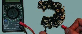
The constant resistor is checked with a multimeter turned on in ohmmeter mode. The result obtained must be compared with the nominal resistance value indicated on the resistor body and on the circuit diagram. When checking trimmer and variable resistors, you first need to check the resistance value by measuring it between the outermost (according to the diagram) terminals, and then make sure that the contact between the conductive layer and the slider is reliable. To do this, you need to connect an ohmmeter to the middle terminal and alternately to each of the outer terminals. When the resistor axis is rotated to its extreme positions, the change in resistance of the variable resistor of group “A” (linear dependence on the angle of rotation of the axis or position of the slider) will be smooth, and the change in the resistance of the variable resistor of group “B” or “C” (logarithmic dependence) is nonlinear. Variable (tuning) resistors are characterized by three malfunctions: violation of contact between the motor and the conductive layer; mechanical wear of the conductive layer with partial breakdown of contact and an upward change in the resistor resistance value; burnout of the conductive layer, as a rule, at one of the outer terminals. Some variable resistors have a dual design. In this case, each resistor is tested separately. Variable resistors used in volume controls sometimes have taps from the conductive layer intended for connecting loudness circuits. To check the presence of contact between the tap and the conductive layer, an ohmmeter is connected to the tap and any of the outer terminals. If the device shows some part of the total resistance, then there is contact between the tap and the conductive layer. Photoresistors are tested similarly to conventional resistors, but they will have two resistance values. One before illumination is the dark resistance (indicated in reference books), the second is when illuminated by any lamp (it will be 10... 150 times less than the dark resistance).
Capacitors
The simplest way to check the serviceability of a capacitor is an external inspection, which reveals mechanical damage, for example, deformation of the housing due to overheating caused by a large leakage current. If no defects are noticed during an external inspection, an electrical test is carried out. An ohmmeter can easily determine one type of malfunction - an internal short circuit (breakdown). The situation is more complicated with other types of capacitor failure: internal break, high leakage current and partial loss of capacitance. The cause of the last type of malfunction in electrolytic capacitors is drying out of the electrolyte.
Many digital testers provide capacitance measurements in the range of 2000 pF to 2000 µF. In most cases this is enough. It should be noted that electrolytic capacitors have a fairly large spread in the permissible deviation from the nominal capacitance value. For some types of capacitors it reaches - 20%, + 80%, that is, if the capacitor rating is 10 μF, then the actual value of its capacitance can be from 8 to 18 μF.
If you don't have a capacitance meter, you can check the capacitor in other ways.
High-capacity capacitors (1 µF and above) are checked with an ohmmeter. In this case, the parts are soldered off from the capacitor if it is in the circuit and discharged. The device is installed to measure high resistances. Electrolytic capacitors are connected to the probes with correct polarity. If the capacitance of the capacitor is more than 1 µF and it is in good condition, then after connecting the ohmmeter, the capacitor is charged, and the arrow of the device quickly deviates towards zero (and the deviation depends on the capacitance of the capacitor, the type of device and the voltage of the power source), then the arrow slowly returns to the “infinity” position. .
If there is a leak, the ohmmeter shows a low resistance - hundreds and thousands of ohms - the value of which depends on the capacitance and type of capacitor. When a capacitor breaks down, its resistance will be near zero. When checking serviceable capacitors with a capacity of less than 1 µF, the instrument needle does not deviate, because the current and charging time of the capacitor are insignificant. When checking with an ohmmeter, it is impossible to determine the breakdown of the capacitor if it occurs at operating voltage. In this case, you can check the capacitor with a megohmmeter at a device voltage that does not exceed the operating voltage of the capacitor. Medium-capacity capacitors (from 500 pF to 1 µF) can be tested using headphones and a current source connected in series to the terminals of the capacitor. If the capacitor is working properly, a click is heard in the headphones when the circuit closes. Small capacitors (up to 500 pF) are tested in a high-frequency current circuit. A capacitor is connected between the antenna and the receiver. If the volume does not decrease, then there are no broken leads.
Transformers, inductors and chokes
The check begins with an external inspection, during which it is necessary to ensure that the frame, screen, and terminals are in good condition; in the correctness and reliability of connections of all parts of the coil; in the absence of visible wire breaks, short circuits, damage to insulation and coatings. Particular attention should be paid to areas of charring of the insulation, frame, blackening or melting of the fill. The most common cause of failure of transformers (and chokes) is their breakdown or short circuit of turns in the winding or broken leads. An open coil circuit or the presence of short circuits between windings isolated according to the circuit can be detected using any tester. But if the coil has a large inductance (i.e., consists of a large number of turns), then a digital multimeter in ohmmeter mode can deceive you (show an infinitely large resistance when there is still a circuit) - the digital multimeter is not intended for such measurements. In this case, an analog dial ohmmeter is more reliable. If there is a circuit being tested, this does not mean that everything is normal. You can make sure that there are no short circuits between the layers inside the winding, leading to overheating of the transformer, by the inductance value, comparing it with a similar product. When this is not possible, you can use another method based on the resonant properties of the circuit. From the tunable generator we apply a sinusoidal signal alternately to the windings through a separating capacitor and control the shape of the signal in the secondary winding.
If there are no interturn short circuits inside, then the signal shape should not differ from sinusoidal over the entire frequency range. We find the resonant frequency by the maximum voltage in the secondary circuit.
Short-circuited turns in the coil lead to disruption of oscillations in the LC circuit at the resonant frequency.
Transformers for different purposes have different operating frequency ranges - this must be taken into account when checking:
- mains supply 40…60 Hz;
- sound separation 10…20000Hz;
- for switching power supply and isolation .. 13… 100 kHz.
Pulse transformers usually contain a small number of turns. If you manufacture them yourself, you can verify their performance by monitoring the transformation ratio of the windings. To do this, we connect the transformer winding with the largest number of turns to a sinusoidal signal generator at a frequency of 1 kHz. This frequency is not very high and all measuring voltmeters (digital and analogue) operate at it, at the same time it allows you to determine the transformation ratio with sufficient accuracy (they will be the same at higher operating frequencies). By measuring the voltage at the input and output of all other windings of the transformer, it is easy to calculate the corresponding transformation ratios.
Diodes and photodiodes
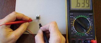
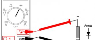
Any pointer (analog) ohmmeter allows you to check the passage of current through a diode (or photodiode) in the forward direction - when the “+” of the tester is applied to the anode of the diode. Turning a working diode back on is equivalent to breaking the circuit. It will not be possible to check the transition with a digital device in ohmmeter mode. Therefore, most modern digital multimeters have a special mode for testing pn junctions (it is marked with a diode on the mode switch).
Such transitions are found not only in diodes, but also in photodiodes, LEDs, and transistors. In this mode, the digital camera works as a source of stable current of 1 mA (this current passes through the controlled circuit) - which is completely safe. When the controlled element is connected, the device displays the voltage at the open pn junction in millivolts: for germanium 200...300 mV, and for silicon 550...700 mV. The measured value can be no more than 2000 mV. However, if the voltage on the multimeter probes is lower than the triggering of the diode, diode or selenium column, then forward resistance cannot be measured.
Bipolar transistors
Some testers have built-in gain meters for low-power transistors. If you do not have such a device, then using a conventional tester in ohmmeter mode or a digital tester in diode testing mode, you can check the serviceability of the transistors.
Testing bipolar transistors is based on the fact that they have two np junctions, so the transistor can be thought of as two diodes, the common terminal of which is the base. For an npn transistor, these two equivalent diodes are connected to the base by anodes, and for a pnp transistor, by cathodes.
The transistor is good if both junctions are good.
To check, one multimeter probe is connected to the base of the transistor, and the second probe is alternately touched to the emitter and collector. Then swap the probes and repeat the measurement.
When testing the electrodes of some digital or power transistors, it should be taken into account that they may have protective diodes installed inside them between the emitter and the collector, as well as built-in resistors in the base circuit or between the base and emitter. Without knowing this, the element may be mistakenly mistaken for faulty.
Field effect transistors
Unlike bipolar, field-effect transistors there are many types and when checking you need to take into account which one you are dealing with. Thus, to test transistors that have a gate based on a pn-junction gate layer, you can use the equivalent circuit shown in the figure
A regular dial ohmmeter is suitable for testing, but it is more convenient to do this with a digital device in the mode of monitoring pn junctions. The resistance between the drain and the source in both directions should have a small value and be approximately the same. Then we measure the forward and reverse resistance of the junction by connecting the ohmmeter probes to the gate and drain (or source). If the transistor is working properly, it should be different in both the forward and reverse directions. When checking the resistance between source and drain, just remember to remove the charge from the gate after previous measurements (briefly short circuit it with the source), otherwise you may get a non-repeatable result. Many low-power field devices (especially those with an insulated gate) are very sensitive to static. Therefore, before picking up such a transistor, make sure that there are no charges on your body. To remove them, it is enough to touch the heating radiator or any grounded objects with your hand, since electrostatic charges between bodies when they separate are distributed in proportion to the mass of the bodies. Therefore, to “neutralize” them, it is often enough to touch even any large ungrounded metal surface. Despite the fact that powerful field-effect transistors are often protected from static, precautions should still not be neglected. A large class of MOSFET transistors (designed to operate in switching mode) do not have pn junctions between the electrodes (insulated gate). Due to the high resistance of the dielectric layer at the gate, if the transistor is not clearly broken (it still wouldn’t hurt to identify this continuity), it will not be possible to verify its functionality - the device will show an infinitely high resistance.
Website materials used: stoom.ru
Tags: [good advice, tool, beginners]
SHARE WITH YOUR FRIENDS:
POPULAR N O E:
- How to choose plastic windows?
- DIY sliding and swing doors
- Lamb made from cotton swabs
What do you need to know when choosing plastic windows?
This question invariably faces everyone who has finally decided to replace windows. To ensure that the window does not disappoint, it is important to immediately provide for all the nuances and identify your needs. In this situation, it is important not only to create aesthetic harmony in the apartment, but also to notice very important details: Read more…
Which door is better to install in your apartment - a traditional swing door or a sliding one?
Of course, swing doors provide better sound insulation than sliding doors.
Yes, if you plan to install a lock on the door, you will also have to turn to the traditional option. Read more…
Making crafts with your children will be an interesting and fun activity. Previously, we made a three-dimensional sheep out of paper, and today we will make a sheep out of... cotton swabs.
Read more…
Popularity: 24,142 views.
Checking inductors
Checking the serviceability of the inductors begins with an external inspection, during which they are convinced of the serviceability of the frame, screen, and leads; in the correctness and reliability of connections of all parts of the coil with each other; in the absence of visible wire breaks, short circuits, damage to insulation and coatings. Particular attention should be paid to areas of charring of the insulation, frame, blackening or melting of the fill.
Electrical testing of inductors includes checking for opens, detecting shorted turns, and determining the condition of winding insulation.
Checking for a break is performed with a probe. An increase in resistance means a break or poor contact in one or more Litz wire cores. A decrease in resistance means the presence of an interturn short circuit. When the terminals are short-circuited, the resistance is zero.
To get a more accurate picture of coil failure, it is necessary to measure the inductance. In conclusion, it is recommended to check the performance of the coil in the same known-good device for which it is intended.
Checking work
Dial icon
Make sure you have connected the probes correctly.
We check the reliability of the connection. To do this, switch the multimeter to diode continuity mode. In this mode, the voltage drop across the probes is measured.
If you close the probes, the device will show zero.
Probe short circuit (zero)
The unit denotes infinity, that is, a break in the circuit or the limit of measurement.
Measurement limit (or break)
Rules for using a multimeter
First you need to familiarize yourself with the technical data sheet of the device, study its capabilities and measurement limits.
When taking measurements, do not touch the metal base of the probes. If you check the details, this may affect the readings, they will be false. And when testing high voltages, if you touch the metal base of the probes, you can get an electric shock.
Checking transformers and low frequency chokes
In terms of design and manufacturing technology, power transformers, transformers and LF chokes have much in common. Both consist of windings made of insulated wire and a core.
Malfunctions of transformers and LF chokes are divided into mechanical and electrical. Mechanical failures include: breakage of the screen, core, leads, frame and mounting hardware; electrical failures include winding breaks; short circuits between turns of windings; short circuit of the winding to the housing, core, screen or fittings; breakdown between the windings, on the housing or between the turns of one winding; reduction of insulation resistance; local overheating.
Checking the serviceability of transformers and LF chokes begins with an external inspection. During this process, all visible mechanical defects are identified and eliminated.
Checking for a short circuit between the windings and between the windings and the housing is done with an ohmmeter.
Rice. 1. Scheme for testing power transformers and low-frequency transformers: a - checking for a short circuit between the winding and the core; 6-check for short circuit between windings; c - checking the transformation ratio at idle.
The device is connected between the terminals of different windings, as well as between one of the terminals and the housing. The insulation resistance is also checked, which must be at least 100 MΩ for sealed transformers and at least tens of MΩ for unsealed ones. The most difficult test for interturn short circuits.
There are several known ways to test transformers (Fig. 1).
- Measuring the ohmic resistance of the winding and comparing the results with the passport data. (The method is simple, but not accurate, especially with a low ohmic resistance of the windings and a small number of short-circuited turns.)
- Checking the coil using a special device - a short-circuited turns analyzer.
- Checking transformation ratios at idle. The transformation ratio is defined as the ratio of the voltages shown by voltmeters 2 and 1. In the presence of interturn short circuits, the transformation ratio will be less than normal.
- Winding inductance measurement.
- Measuring power consumption at idle. In power transformers, one of the signs of short-circuited turns is excessive heating of the winding.
The simplest test of the health of semiconductor diodes
The simplest test of the health of semiconductor diodes is to measure their forward Rpr and reverse Rrev resistances.
The higher the ratio Robr/Rpr, the higher the quality of the diode. To measure, the diode is connected to a tester (ohmmeter) or to an ampere-volt meter, as shown in Fig. 2. In this case, the output voltage of the measuring device should not exceed the maximum permissible for a given semiconductor device.
Rice. 2. Scheme for checking the serviceability of semiconductor diodes.
Rice. 3. Scheme for checking the serviceability of RF diodes.
The serviceability of high-frequency diodes can be checked by connecting them to the circuit of a working simple detector radio receiver, as shown in Fig. 3. Normal operation of the radio indicates that the diode is working properly, and lack of reception indicates its breakdown.
Setting up the multimeter
First, you need to set up the multimeter to work.
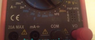
Probe connectors
Multimeters have 3 to 4 probe connectors. In 90% of measurements, only two connectors will be needed. These are COM and VΩ.
The black probe of the multimeter is always connected to COM. The default black probe is negative, the common wire. That's why it's called COM.
To measure voltage, resistance or continuity of radio components, the red probe is connected to the VΩ connector.
Where is the plus on the millimeter?
By default, the positive wire is the red wire if you have it connected correctly. The black probe of a multimeter is always a minus, and it is inserted into the COM connector regardless of the operating mode.
Simple transistor test
When repairing household radio equipment, it becomes necessary to check the serviceability of semiconductor triodes (transistors) without removing them from the circuit. One way to do this is to measure the resistance with an ohmmeter between the emitter and collector terminals when connecting the base to the collector (Fig. 4, a) and when connecting the base to the emitter (Fig. 4.6).
In this case, the collector power source is disconnected from the circuit. If the transistor is working properly, in the first case the ohmmeter will show low resistance, in the second - on the order of several hundred thousand or tens of thousands of ohms.
Transistors not included in the circuit are checked for short circuits by measuring the resistance between their electrodes. To do this, the ohmmeter is connected alternately to the base and emitter, to the base and collector, to the emitter and collector, changing the polarity of the ohmmeter connection.
Rice. 4. Scheme for checking the serviceability of transistors.
Rice. 5. Checking the transistor using an ohmmeter.
Since the transistor consists of two junctions, each of which is a semiconductor diode, you can test the transistor in the same way as you test a diode.
To check the serviceability of the transistors, an ohmmeter is connected to the corresponding terminals of the transistor (Fig. 5 shows how the forward and reverse resistance of each of the transistor transitions is measured). For a working transistor, the forward transition resistances are 30-50 Ohms, and the reverse ones are 0.5-2 MOhms.
If there are significant deviations from these values, the transistor can be considered faulty. When checking RF transistors, the ohmmeter battery voltage should not exceed 1.5 V. For a more thorough check of transistors, special devices are used.
Checking parts with a digital multimeter.
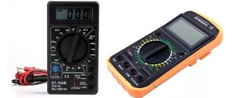
The main difference between a digital device and an analog one is that the measurement results are displayed on a liquid crystal display. In addition, digital multimeters have higher accuracy and are easy to use, because you don’t have to understand all the intricacies of grading the measuring scale, as with dial measuring instruments. The digital tester (see Fig. 1), like the analog one, has two probes - black and red, and from two to four sockets. The black pin is common (ground). The socket for the common output is marked as COM or simply “-” (minus), and the output itself at the end often has a so-called crocodile, so that during measurements it can be hooked to the ground of the electronic circuit. The red lead is inserted into the socket marked with voltage symbols - “V” or “+” (plus). If your device contains more than two sockets, for example, as in Fig. 1, the red probe is inserted into the “VQmA” socket. This inscription means that you can measure voltage, resistance and small current - in milliamps. The socket, positioned slightly higher, marked 10ADC indicates that you can measure high direct current, but not higher than 10A. The multimeter switch allows you to select one of several measurement limits. To measure direct voltage, select the DCV1 mode; if variable is ACV, connect the probes and look at the result. In this case, on the switch scale you must select a higher voltage than the one being measured. For example, you need to measure the voltage in an electrical outlet. In your device, the ACV scale consists of two parameters: 200 and 750 (these are volts). This means that you need to set the switch arrow to parameter 750 and you can safely measure the voltage.
1 DC – direct current (Direct Current), AC – alternating current (Alternating Current).
The current is measured by connecting a multimeter in series to an electrical circuit. For example, you can take a regular light bulb from a flashlight and connect it in series with the device to a 5V adapter. Current will flow through the circuit and the light will light up, the device will show the current value. The resistance on the device is indicated by an icon that looks a little like headphones. To measure resistance, the resistor must be unsoldered from the electrical circuit at least on one end to ensure that no other components in the circuit affect the result. We connect the probes to the two ends of the resistor and compare the ohmmeter readings with the value indicated on the resistor itself. It is also worth considering the magnitude of the tolerance (possible deviations from the norm), i.e. If according to the marking the resistor is 200 kOhm and has a tolerance of ± 15%, its actual resistance can be in the range of 170-230 kOhm. When checking variable resistors , we first measure the resistance between the extreme terminals (must correspond to the resistor value), and then by connecting the multimeter probe to the middle terminal, alternately with each of the extreme terminals. When the axis of the variable resistor is rotated, the resistance should change smoothly, from zero to its maximum value; in this case, it is more convenient to use an analog multimeter watching the movement of the needle than quickly changing numbers on the liquid crystal screen. To test diodes, standard devices contain a special mode. In cheaper testers, you can use the dialing mode. Everything is simple here: the diode rings in one direction, but not in the other. You can also check the diode in resistance mode. To do this, set the switch to 1k0m. When you connect the red lead of the multimeter to the anode of the diode, and the black lead to the cathode, you will see its direct resistance; when connected in reverse, the resistance will be so high that at this measurement limit you will not see anything. If a diode is broken, its resistance in any direction will be zero; if it is broken, then its resistance in any direction will be infinitely large. A conventional bipolar transistor consists of two diodes connected towards each other. Knowing how diodes are tested, it is easy to test such a transistor. It is worth remembering that transistors come in different types: in p-p-r conventional diodes are connected by cathodes, in p-p-p - by anodes. To measure the direct resistance of transistor pn-p junctions, the minus of the multimeter is connected to the base, and the plus alternately to the collector and emitter. When measuring reverse resistance, we change the polarity. To test p-p-n transistors, we do the opposite. To put it even more briefly, the base-collector and base-emitter transitions should be connected in one direction, but not in the other. To measure the current gain of a transistor, we use the hEF mode, if your device has it. The connector into which the transistor contacts are inserted to measure hEF is not of very high quality in almost all tester models and is set quite deep. That is, the legs of the transistor sometimes do not reach them. As a way out, insert single-core wires and touch them with the terminals of the transistor. Digital multimeters usually have larger measurement ranges, and often add additional functions, such as a frequency meter, a capacitance meter, and even a temperature sensor. But more expensive tester models have such capabilities. In addition, in expensive models there is no need to switch the measurement scale. Just set the switch to measure capacitance, resistance, etc., and the device shows the result.
To ensure that the multimeter does not fail when measuring voltage or current, especially if their value is unknown, it is advisable to set the switch to the highest possible measurement limit, and only if the reading is too small, to obtain a more accurate result, switch the multimeter to a lower limit current.
Checking galvanic batteries and dry cells
Galvanic batteries and dry cells are checked using a voltmeter with a connected load (Fig. 7). The load can be either an incandescent lamp with the corresponding rated current, or a resistor її, the resistance of which is calculated according to Ohm's law.
Rice. 7. Checking galvanic batteries and dry cells using a voltmeter with a connected load.
For dry cells (1.5 V), the voltage measured under load should not be less than 1.36 V, and for galvanic batteries - 4.5 V - 3.8...4 V.

