03/21/2016 master
Diode
Today we can’t live without electronics. It is an integral part of any modern device or gadget. At the same time, all devices, sadly, cannot work forever and periodically break down. One of the fairly common causes of failure of a number of electrical appliances is the failure of an electrical element such as a diode.
You can check the serviceability of this component yourself at home. This article will tell you how to test a diode with a multimeter, as well as what these elements are and what the measuring device itself is.
Design
The Schottky diode differs from ordinary diodes in its design, which uses a metal-semiconductor rather than a pn junction. It is clear that the properties here are different, which means the characteristics should also be different.
Indeed, a semiconductor metal has the following parameters:
- Leakage current is of great importance;
- Low voltage drop across the junction when connected directly;
- Restores charge very quickly, as it has a low value.
The Schottky diode is made of materials such as gallium arsenide, silicon; much less commonly, but can also be used, is germanium. The choice of material depends on the properties that need to be obtained, however, in any case, the maximum reverse voltage for which these semiconductors can be manufactured is not higher than 1200 volts - these are the highest voltage rectifiers. In practice, they are much more often used at lower voltages - 3, 5, 10 volts.
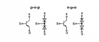
In the circuit diagram, the Schottky diode is designated as follows:
But sometimes you can see this designation:
This means a dual element: two diodes in one housing with a common anode or cathode, so the element has three terminals. Power supplies use such designs with a common cathode; they are convenient to use in rectifier circuits. Often the diagrams show the markings of a regular diode, but the description indicates that this is a Schottky diode, so you need to be careful.
Diode assemblies with a Schottky barrier are available in three types:
Type 1 – with a common cathode;
Type 2 – with a common anode;
Type 3 – according to the doubling scheme.
This connection helps to increase the reliability of the element: after all, being in the same housing, they have the same temperature regime, which is important if powerful rectifiers are needed, for example, 10 amperes.
But there are also disadvantages. The thing is that the low voltage drop (0.2–0.4 V) of such diodes appears at low voltages, usually 50–60 volts. At higher values they behave like regular diodes. But in terms of current, this circuit shows very good results, because it is often necessary - especially in power circuits and power modules - for the operating current of semiconductors to be at least 10A.
Another major disadvantage: for these devices, the reverse current cannot be exceeded even for an instant. They immediately fail, while silicon diodes, if their temperature has not been exceeded, restore their properties.
But there are still more positive things. In addition to the low voltage drop, the Schottky diode has a low junction capacitance value. As you know: lower capacity - higher frequency. Such a diode has found application in switching power supplies, rectifiers and other circuits with frequencies of several hundred kilohertz.
Current-voltage characteristic of the LED (volt-ampere characteristic)
The current-voltage characteristic of such a diode has an asymmetrical appearance. When a forward voltage is applied, it is clear that the current increases exponentially, and when reverse voltage is applied, the current does not depend on the voltage.
All this can be explained if you know that the operating principle of this semiconductor is based on the movement of the main carriers - electrons. For the same reason, these devices are so fast: they do not have recombination processes characteristic of devices with pn junctions. All devices with a barrier structure are characterized by asymmetry of the current-voltage characteristics, because it is the number of electric charge carriers that determines the dependence of current on voltage.
Significant characteristics of protection diodes
- Utrial _ (breakdown)
The voltage value at which the diode opens and the potential is transferred to the common wire. An additional synonymous designation is VBR.
Maximum reverse leakage current. It has a small value, measured in microamps, and the functionality of the device practically does not depend on it. Additional designation - IR.
The value is an indicator of constant reverse voltage. V.R.W.M.
The highest value for limiting impulse voltage. VCL, VCmax.
The highest value of the peak pulse current. Otherwise, this is an indicator of the greatest strength of the current pulse that is safe for the protective diode. For the most effective limiting zener diodes, this value can be hundreds of amperes. IPP.
Indicator of the highest value of permissible pulse power. Unfortunately, this parameter is extremely dependent on the pulse duration.
Fig. 2 VA characteristics of the protective diode
The power level of protection diodes is not the same. However, if the suppressor does not have enough initial data on this parameter, it can easily be combined with one or more semiconductors, which will have a positive effect on the overall power level.
Miniaturization
With the development of microelectronics, special microcircuits and single-chip microprocessors began to be widely used. All this does not exclude the use of hanging elements. However, if radioelements of conventional sizes are used for this purpose, this will negate the whole idea of miniaturization as a whole. Therefore, open-frame elements were developed - SMD components, which are 10 or more times smaller than conventional parts. The current-voltage characteristics of such components are no different from the current-voltage characteristics of conventional devices, and their reduced dimensions make it possible to use such spare parts in various microassemblies.
SMD components come in several sizes. SMD size 1206 is suitable for manual soldering. They have a size of 3.2 by 1.6 mm, which allows you to solder them yourself. Other SMD elements are more miniature, assembled at the factory with special equipment, and it is impossible to solder them yourself at home.
The operating principle of an smd component is also no different from its large counterpart, and if, for example, we consider the current-voltage characteristic of a diode, then it will be equally suitable for semiconductors of any size. The current range is from 1 to 10 amperes. The markings on the case often consist of a digital code, the decoding of which is given in special tables. They can be tested for suitability using a tester, just like their larger counterparts.
How to check an LED spotlight
Internal structure of the spotlight
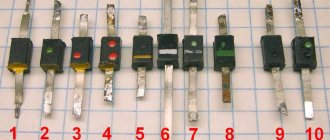
The LED is checked after determining the type of element. The following are installed on the lanterns:
- a board with small SMDs, which are checked by continuity in the same way as a standard light bulb;
- a large yellow element operating on a voltage of 10-30 V.
The voltage of a large element is high for the tester, so the operability of the element can only be determined by the driver. It must match the performance of the diode.
Use in practice
Schottky rectifiers are used in switching power supplies, voltage stabilizers, switching rectifiers. The most demanding current - 10A or more - are voltages of 3.3 and 5 volts. It is in such secondary power circuits that Schottky devices are most often used. To amplify the current values, they are connected together in a circuit with a common anode or cathode. If each of the dual diodes is rated at 10 amperes, you will get a significant safety margin.
One of the most common malfunctions of switching power modules is the failure of these same diodes. As a rule, they either completely break through or leak. In both cases, the faulty diode must be replaced, then the power transistors must be checked with a multimeter, and the supply voltage must also be measured.
Checking the LED with a battery
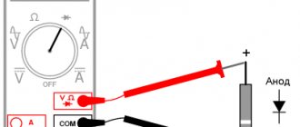
To test the LED using a battery, you need to assemble the circuit according to the diagram.
Diagram for checking LED1 from a 9V battery.
On the diagram:
- LED1 – device being tested.
- 9V – power source (battery with a voltage of 9V).
- VAΩ is a measuring device for measuring V – voltage, A – current, Ω – resistance, AVOmeter or multimeter. In the diagram it works in voltage measurement mode.
- R1 is a current limiting resistor.
- R2 is a variable resistor that sets the brightness of the LED.
Resistor R2 on the multimeter sets the rated operating current. A working LED element produces light. Faulty - no light.
The term “multimeter” is a transliteration of the international name “Multimeter”. Derived from the terms Multi – many and meter – to measure. It has the names “tester”, “AVOmeter” - from Ampere-Volt-Ohmmeter.
A modern multimeter is a universal measuring device with a digital display.
One of the types of multimeters.
Another name for the device is “tester” - a Cyrillic transliteration of the international term tester - tester, verifier, tester.
Testing and interchangeability
Schottky rectifiers can be tested in the same way as conventional semiconductors, since they have similar characteristics. You need to ring it in both directions with a multimeter - it should show itself in the same way as a regular diode: anode-cathode, and there should be no leaks. If it shows even a slight resistance - 2-10 kilo-ohms, this is already a reason for suspicion.
Read also: Installing a wet rotor pump
Checking a Schottky diode with a multimeter
A diode with a common anode or cathode can be tested like two ordinary semiconductors connected together. For example, if the anode is common, then it will be one leg out of three. We place one tester probe on the anode, the other legs are different diodes, and another probe is placed on them.
Can it be replaced with another type? In some cases, Schottky diodes are replaced with ordinary germanium diodes. For example, D305 at a current of 10 amperes gave a drop of only 0.3 volts, and at currents of 2–3 amperes they can generally be installed without radiators. But the main purpose of the Schottky installation is not a small drop, but a low capacity, so replacement will not always be possible.
As we see, electronics does not stand still, and further applications of high-speed devices will only increase, making it possible to develop new, more complex systems.
Operating principle
The operating principle of a Schottky diode is almost no different from semiconductor diodes. A special feature is the presence of metal. A typical semiconductor uses two substances that form electrons with a positive and a negative charge inside them. When an electric current passes, part of the charge is lost to the formation of these electrons.
A Schottky diode uses a metal and a semiconductor. Gold, silicon, and germanium are used as metal barriers in production. A diode also consists of an anode and a cathode. When voltage is applied to the anode, the metal creates a magnetic barrier to the direct passage of voltage. Electrons with a negative charge are created on its surface. When a significant magnetic field is formed, the element is pulsedly discharged. Such a discharge can be repeated an infinite number of times, subject to the operating voltage and temperature.
The most comfortable voltage for this type of diode is 40–60 volts. It is this voltage that allows the transition to be made without losing a fraction of the voltage and without increasing the temperature.
Temperature also plays a significant role in the rapid transfer of charges. When the input voltage is low, a temperature rise is created. Due to this, the number of charged electrons increases, which quickly overcome the metal barrier.
Checking a Diode with a Digital Multimeter
To determine the health of the diode, you can use the following method for checking it with a digital multimeter.
But first, let's remember what a semiconductor diode is.
A semiconductor diode is an electronic device that has the property of unidirectional conductivity.
The diode has two terminals. One is called the cathode, which is negative. The other output is the anode. It is positive.
At the physical level, the diode is a single pn junction.
Let me remind you that semiconductor devices can have several pn junctions. For example, the dinistor has three of them! A semiconductor diode is essentially the simplest electronic device based on just one pn junction.
Let us remember that the operating properties of the diode appear only when connected directly. What does direct connection mean? This means that a positive voltage (+) is applied to the anode terminal, and a negative voltage is applied to the cathode, i.e. ( – ). current begins to flow through its pn junction .
When turned on in reverse, when a negative voltage ( – ) is applied to the anode and a positive voltage (+) is applied to the cathode, the diode is closed and does not allow current to pass through .
This will continue until the voltage on the reverse-connected diode reaches a critical value, after which damage to the semiconductor crystal occurs. This is the main property of the diode - one-way conductivity.
The vast majority of modern digital multimeters (testers) have the ability to test a diode in their functionality. This function can also be used to test bipolar transistors. It is indicated in the form of a diode symbol next to the marking of the multimeter mode switch.
A little note! It is worth understanding that when checking diodes in direct connection, the display does not show the transition resistance, as many people think, but its threshold voltage ! It is also called the voltage drop across the pn junction . This is the voltage above which the pn junction opens completely and begins to pass current. If we draw an analogy, this is the amount of effort aimed at opening the “door” for electrons. This voltage ranges from 100 to 1000 millivolts (mV). This is what the device display shows.
In reverse connection, when the negative ( – ) terminal of the tester is connected to the anode, and the positive (+) terminal is connected to the cathode, then no values should be shown on the display. This indicates that the junction is working properly and does not allow current to flow in the opposite direction.
In the documentation (datasheets) for imported diodes, the threshold voltage is referred to as Forward Voltage Drop (abbreviated Vf ), which literally translates as “ voltage drop in direct connection .”
The voltage drop across the pn junction itself is undesirable. If we multiply the current flowing through the diode (direct current) by the magnitude of the voltage drop, then we get nothing more than power dissipation - the power that is uselessly spent on heating the element.
You can find out more about the diode parameters here.
Diode check.
To make it more clear, let’s check the 1N5819 rectifier diode. This is a Schottky diode. We will soon see this.
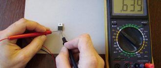
We will perform the test using the Victor VC9805+ multitester. Also, for convenience, a solderless breadboard is used.
I draw your attention to the fact that during measurements you cannot hold the leads of the element being tested and the metal probes with both hands. This is a big mistake. In this case, we measure not only the parameters of the diode, but also the resistance of our body. This can significantly affect the result of the test.
Read also: Why do you need to move the wire during EDM cutting?
You can hold the probes and terminals of the element with only one hand! In this case, only the measuring device itself and the element being tested are included in the measuring circuit. This recommendation is also valid when measuring the resistance of resistors, as well as when checking capacitors. Don't forget this important rule!
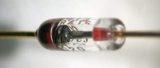
So, let's check the diode in direct connection. In this case, we connect the positive probe (red) of the multimeter to the anode of the diode. the negative probe ( black ) to the cathode. In the photo shown earlier, you can see that the cylindrical body of the diode has a white ring on one edge. It is on this side that it has a cathode terminal. This is how the cathode terminal of most imported diodes is marked.
As you can see, the threshold voltage value for 1N5819 appeared on the display of the digital multimeter. Since this is a Schottky diode, its value is small - only 207 millivolts (mV).
Now let's check the diode in reverse connection. We remind you that when switched in reverse, the diode does not allow current to pass through. Looking ahead, we note that in the reverse connection, a small current still flows through the pn junction. This is the so-called reverse current ( Irev ). But it is so small that it is usually not taken into account.
Let's change the connection of the diode to the multimeter's test leads. We connect the red probe to the cathode, and the black probe to the anode.
The display will show “ 1 ” in the most significant digit of the display. This indicates that the diode does not pass current and its resistance is high. Thus, we checked the 1N5819 diode and it turned out to be fully functional.
Many people ask the question: “Is it possible to test a diode without desoldering it from the board?” Yes, you can. But in this case, it is necessary to remove at least one of its pins from the board. This must be done in order to exclude the influence of other parts that are connected to the diode being tested.
If this is not done, then the measuring current will flow through everything, including through the elements connected to it. As a result of testing, the multimeter readings will be incorrect!
In some cases, this rule can be neglected, for example, when it is clearly visible that there are no parts on the printed circuit board that could affect the test result.
Diode faults.
The diode has two main faults. This is a breakdown of the transition and its break .
Breakdown . During a breakdown, the diode turns into an ordinary conductor and freely passes current, either in the forward direction or in the reverse direction. In this case, as a rule, the multimeter buzzer beeps, and the display shows the value of the junction resistance. This resistance is very small and amounts to several ohms, or even zero.
Break . When broken, the diode does not pass current either in forward or reverse connection. In any case, the device display shows “ 1 ”. With such a defect, the diode is an insulator. “Diagnosis” - a break can be accidentally caused to a working diode. This is especially easy to do when the tester probes are worn out and damaged. Make sure that the measuring probes are in good condition; their wires are oh-so-thin and easily break with frequent use.
And now a few words about how the value of the threshold voltage (voltage drop at the junction - Forward Voltage Drop ( Vf )) can be used to roughly judge the type of diode and the material from which it is made.
Here is a small selection made up of specific diodes and their corresponding Vf , which were obtained when testing them with a multimeter. All diodes were previously checked for serviceability.
Determining the suitability of radio components is the main procedure carried out when repairing or servicing electronic equipment. And if everything is more or less clear with passive elements, then active ones require special approaches. It is not difficult to check the resistance of a resistor or the integrity of an inductor.
With active ingredients the situation is a little more complicated. It is necessary to separately understand how to check a diode with a multimeter with your own hands, given that this is the simplest and most common semiconductor element of electronic circuits.
Analyzing the results
When checking diodes (regular and Schottky) with a multimeter, you will get a certain result. Now we need to understand what it could mean. Signs that indicate the health of the semiconductor include the following:
- when connecting a part of the electrical circuit to the device, the latter will output the value of the available direct voltage in this element;
Note! Different types of diodes have different voltage levels, which is why they differ. For example, for germanium products this parameter will be 0.3-0.7 volts
- when connected in the opposite way (the probe of the device to the anode of the product), zero will be recorded.
Reverse check
If these two indicators are met, then the semiconductor is working adequately and the cause of the failure is not in it. But if at least one of the parameters does not correspond, then the element is considered unusable and must be replaced. In addition, it should be borne in mind that it is not a breakdown, but a “leakage” that is possible. This unpleasant defect can appear during long-term use of the device or poor-quality assembly. If there is a short circuit or leakage, the resulting resistance will be quite low. Moreover, the conclusion must be made based on the type of semiconductor. For germanium elements, this indicator in this situation will range from 100 kilo-ohms to 1 mega-ohm, for silicon - thousands of mega-ohms. For rectifier semiconductors, this figure will be many times higher. As you can see, it is not so difficult to assess the performance of semiconductors in any electrical device on your own. The above principle is suitable for testing diode elements of various types and types. The main thing in this situation is to correctly connect the measuring device to the semiconductor and analyze the results obtained.
Types of diodes and their purpose
In short, a diode is a semiconductor component in an electronic circuit designed to carry current in one direction. In other words, the device passes current in one direction, blocking its flow in the opposite direction, forming a kind of electric valve.
On circuit diagrams, the diode is indicated by a pointer arrow, at the end of which there is a line indicating locking. The arrow indicates the direction of current flow. It must be remembered that in theoretical physics, current is formed by positively charged particles. Therefore, to open a pn junction, a positive potential is applied to the beginning of the arrow, and a negative potential to its end. Under such conditions, direct current will flow through the device.
Let's consider the most common types of diodes, given that only a few are of interest in terms of testing, namely:
- conventional diodes based on a pn junction;
- with a Schottky barrier, more often called simply Schottky diodes;
- Zener diode, which serves to stabilize the potential and other types.
There are many more types of diodes - varicaps, LEDs or photodiodes, for example. But due to the similarity of performance testing or low prevalence, these devices are not considered here.
Nuances of testing infrared diodes
Testing an Infrared LED
The infrared LED produces invisible radiation, so it is important to monitor the readings on the multimeter display. The probes are installed by applying plus to the anode and minus to the cathode. By touching the probes to the working IR diode, you can see the number 1000 on the screen. When the polarity is changed, 1 is displayed.
To accurately check the infrared diode with transistor sockets, a smartphone camera or digital device is used. The IR LED will need to be placed in the transistor sockets and the camera pointed at it. Serviceability is indicated by a glowing blurry spot on the gadget’s display.
Soldering a parallel red LED glow will clearly reflect the performance of the diode. If a signal is supplied to the element at the moment of flickering, it should be replaced. If the backlight does not work, the remote control is faulty.
Defining an Element Type
It’s good if the size of the case allows you to put at least somewhat understandable markings on it. But most often the diodes are so small that it is difficult to mark them even with color. In this case, it is not possible to distinguish a diode from a zener diode, for example, because they are like twin brothers.
Read also: Chainsaw partner 350 where is the breather located
In such situations, only a schematic diagram of the apparatus from which the element was extracted will help. In accordance with it, you can determine the type of component and its brand. If this information is missing, you can try to search for a schematic diagram of the device being repaired on the Internet or take a photograph of the element and also go to the Internet and search by image.
Testing diodes with a multimeter or other tester should only be done after determining their type and brand, because different types are tested differently.
Features of checking LED light bulbs
Using a multimeter, you can test color, standard and super-bright diodes.
Standard light bulb with E27 base
Checking an LED lamp
A similar lamp is used for household chandeliers or lamps. To check whether an LED is working or not working, you will need:
- Remove the diffuser from the light bulb using a plastic bank card placed between the element and the body.
- Carefully move the plastic card along the glue. A durable seam can be heated with a hair dryer.
- Open the board.
- Touch the elements with probes and wait until they glow with a dim glow.
If the diodes do not light, the light bulb is broken.
Super bright diodes
Checking a powerful diode
A garland is usually equipped with blue, yellow or white LEDs. The test is carried out without probes using transistor sockets according to the following algorithm:
- Determine the pinout of the SMD.
- Find 8 sockets at the bottom of the device - 4 left ones for PNP transistors and 4 right ones for NPN transistors.
- Place the probes by inserting the anode into hole E and the cathode into hole C.
- Open the PNP element by applying a positive charge to the emitter E. A working LED will light up.
- Change the polarity of transistors for NPN. The anode is placed on C, the cathode - on E.
Transistor sockets are useful for testing diodes with long contacts without solder.
Application of the tester
The simplest, but no less effective, device for testing elements of electronic circuits, semiconductor diodes, including, is a radio component tester. Moreover, this instrument is the most common among radio technicians due to its unpretentiousness, small weight and size parameters and the ability to measure almost any characteristics of radio elements and circuits important for repairs.
It is believed that digital multimeters, due to their accuracy and ease of use, are gradually replacing analog ones. However, you shouldn’t compromise on the accuracy of the old “tseshka”. It already includes microcircuits, and bridge resistors have an error of 1-2% (this is very high accuracy even for integrated circuits). Therefore, to check the serviceability of a diode or transistor, there is no need to buy a new multimeter, if you have an analog one.
Digital display has taken root due to the lack of mechanical components in the multimeter. This increased its impact resistance and service life.
Checking diodes has been simplified with the advent of a sound signal, which allows you not even to pay attention to the display. Most multimeters have a special mode that allows you to literally and figuratively ring the diode. It is marked on the body with the corresponding sign.
Just insert the black plug into the COM connector, and the red plug into the resistance measurement connector (Ω), set the switch to diode testing mode, and you can start testing.
LED strip testing procedure
Each section from one point (plus and minus) to another is checked for integrity or breakage.
It is problematic to check the LED strip with a multi-meter, since it does not glow. Weak light occurs when testing in Hfe mode. Testing is also complicated by burnouts not of the diodes themselves, but of the contact tracks or current-carrying sections. To find out about a problem:
- Find conditional identical segments of 3 LEDs along the border of the contacts and the transverse strip.
- Touch the probes to each area in turn, applying current to the power contacts.
- Ring the power supply - it fails due to load drop.
Checking the resistance will provide a complete picture of the integrity of the LEDs.
Test method
Checking diodes with a multimeter consists of determining the functionality of their pn junction. In general, there are only two malfunctions in radio electronics. The first is a circuit break (burnout) when current does not flow in either direction. The second is caused by a short circuit (breakdown) of the electrodes, which turns the component into a piece of ordinary wire.
The testing methodology is extremely simple. When connecting the anode to the positive probe of the multimeter, and the cathode to the negative probe, the pn junction must be open, therefore, its resistance is close to zero. Digital meters should produce a characteristic signal. When connecting in reverse, the pn junction must be locked, as evidenced by its infinite (in theory) resistance. The digital tester displays the number 1. This is how the working diode rings. If current passes, regardless of the polarity of the connection, there is a short circuit. In the case when the device does not ring in either direction, a gap occurs.
You can often hear the question of how to test a Schottky diode. Indeed, these components are fundamentally different from others. The fact is that the pn junction, even in the open state, has a resistance, albeit small. This in turn causes energy loss, dissipated as heat. To reduce the latter, one of the semiconductor electrodes of the diode was replaced with metal. And although the loss current in this case increases slightly, in the open state the junction resistance is very low, which makes the device economical. Otherwise, testing a Schottky diode using a multimeter is no different from testing a regular pn junction.
Device structure
Sooner or later, the day when it will not be possible to heat food in a microwave will come in every home. Of course, this is regrettable, but you cannot insure yourself against certain breakdowns. In this case, the device will not always give an obvious “distress signal” in the form of a stream of smoke and other visual effects. Otherwise, it is unlikely that you will be able to repair the breakdown yourself. You will have to contact a specialist, and this will cost a pretty penny. If the device stops working without “special effects,” then there is a chance to fix it yourself. There are some malfunctions, the diagnosis of which and elimination of the causes of the breakdown will be quite cheap. And you won’t have to spend money on expensive repairs or purchasing a new model. But for this you need to know the structure of a microwave oven. Despite the abundance of different models and manufacturers, the operating principle of a microwave oven and its design remains unchanged. The device is assembled from the following components:
- high voltage power transformer;
- high voltage diode;
- high voltage capacitor;
- magnetron;
- fan for cooling the magnetron;
- thermal fuse that protects the magnetron from overheating;
- network filter;
- an electric motor for rotating a cup with food placed on it;
- limit switches.
Inside view
The serviceability of all of the above components of the device ensures uninterrupted operation of the device throughout the entire period of operation.
Zener diodes
The issue of checking zener diodes stands apart. There is no point in checking them using the method described above, unless you can verify the integrity of the pn junction. Unlike a conventional rectifier diode, a zener diode uses the reverse branch of the current-voltage characteristic (VAC). Therefore, to study the stabilizing properties, the operating point must be shifted precisely to this section of the graph.
To do this, a simple circuit consisting of a power source and a current-limiting resistor is used. In this case, the multimeter measures not the junction resistance, but the voltage, with a smooth increase in the supply potential. A zener diode is considered working if, when the supply voltage increases, the potential difference at its electrodes remains constant and equal to that stated in the documentation for the device.
Significant characteristics of protection diodes
- Utrial _ (breakdown)
The voltage value at which the diode opens and the potential is transferred to the common wire. An additional synonymous designation is VBR.
Maximum reverse leakage current. It has a small value, measured in microamps, and the functionality of the device practically does not depend on it. Additional designation - IR.
The value is an indicator of constant reverse voltage. V.R.W.M.
The highest value for limiting impulse voltage. VCL, VCmax.
The highest value of the peak pulse current. Otherwise, this is an indicator of the greatest strength of the current pulse that is safe for the protective diode. For the most effective limiting zener diodes, this value can be hundreds of amperes. IPP.
Indicator of the highest value of permissible pulse power. Unfortunately, this parameter is extremely dependent on the pulse duration.
Fig. 2 VA characteristics of the protective diode
The power level of protection diodes is not the same. However, if the suppressor does not have enough initial data on this parameter, it can easily be combined with one or more semiconductors, which will have a positive effect on the overall power level.
A TVS diode can act as a zener diode. But first you need to check its maximum power dissipation and dynamic current at Imax. and Imin.
Without desoldering
Separately, you need to consider whether it is possible to test with a multimeter directly on the board without soldering the element from it. It all depends on the complexity of the scheme and the qualifications of the master. A product mounted on a board can ring through transformer windings, resistive elements, a burnt capacitor, or something else. Therefore, it is most often not possible to obtain more or less adequate indicators.
Of course, if the master reads the circuit diagram like an open book or has become familiar with similar devices, he can evaluate the performance of the device. There are even testing methods without dismantling for automotive power supplies, for example.
But it’s better to unsolder the element from the circuit. In addition, it is enough to “hang in the air” only one leg of the product, which takes 2-3 seconds. And after testing with a multimeter for the same period of time, the diode returns to its original position on the board.
Causes of failure
All microwave ovens work properly for quite a long period of time. This is due, first of all, to the high reliability of the components. But over time, some of them fail, despite careful operation of the equipment. Therefore, you need to check all the components. The most common malfunctions of the following spare parts are:
- High voltage fuse;
- Capacitor;
- Transformer failure;
- Rectifier diode.
Each of these faults can be corrected independently. As a rule, microwave oven owners have to deal with the diode in case of problems with the operation of the device.
The high-voltage diode may not be immediately noticeable if you are disassembling the microwave for the first time.