What is a semiconductor diode - AC rectifier
Diodes are two-electrode devices that have one-way conductivity of electric current.
This main property is used, for example, in rectifiers, where diodes convert alternating current from the mains into direct current to power radio equipment, in receivers - to detect modulated high-frequency oscillations, that is, convert them into low (sound) frequency oscillations. A clear illustration of this property of a diode can be seen in the following experiment. In a circuit made up of a 3336L battery and a light bulb from a flashlight (3.5 V X 0.26 A), connect any planar diode, for example, from the D226 or D7 series, but so that the anode of the diode, designated conventionally by a triangle, would be connected directly or through a light bulb to the positive pole of the battery, and the cathode, indicated by the dash to which the corner of the triangle adjoins, to the negative pole of the battery. The light should be on.
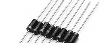
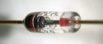
Diode sizes.
Change the polarity of the battery to reverse - the light will not light. If the resistance of a diode is measured with an ohmmeter, depending on how you connect it to the terminals of the device, the ohmmeter will show different resistance: in one case it is small (units or tens of ohms), in the other it is very large (tens and hundreds of kilo-ohms). This confirms the one-way conductivity of the diode.
The diode has two electrodes: the cathode is negative and the anode is positive (Fig. 13). The cathode is a plate of germanium, silicon or some other semiconductor with electronic conductivity, or abbreviated n-type semiconductor (n is the initial letter of the Latin word negativus - “negative”), and the anode is part of the volume of the same plate, but so called hole conductivity, or abbreviated p-type semiconductor (p is the initial letter of the Latin word positivus - “positive”).
A so-called p-n junction is formed between the electrodes - a boundary zone that conducts current well from the anode to the cathode and poorly in the opposite direction (the direction of the current is taken to be the direction opposite to the movement of electrons). The diode can be in one of two states: open, that is, passing, or closed, that is, non-passing. The diode is open when a direct voltage Upr is applied to it, otherwise, its anode is connected to the plus of the voltage source, and the cathode is connected to the minus.
In this case, the resistance of the pn junction of the diode is small and a direct current IPre flows through it, the strength of which depends on the load resistance (in our experience, a flashlight bulb). With a different polarity of the supply voltage, reverse voltage Urev is applied to the pn junction of the diode. In this case, the diode is closed, its resistance is high and only a small reverse diode current Irev flows in the circuit. The dependence of the current passing through the diode on the value and polarity of the voltage at its electrodes is best judged by the current-voltage characteristic of the diode, which can be measured experimentally.
Different types of diodes.
LED connection.
The simplest way to connect an LED is to connect it with a resistor. The latter is necessary for current limiting to prevent LED burnout during voltage surges.
When connecting LED elements according to any scheme, do not forget to maintain polarity! Otherwise, the semiconductor device will not glow and will burn out.
Electrical diagram for connecting an LED (LED) and a resistor (R).
When connecting several light-emitting diodes, different options for connecting them are possible.
Serial connection.
Serial connection diagram.
The elements are connected in series, taking into account polarity. In the circuit, the current value is constant, and the voltage across the LED elements is summed up.
Parallel connection.
Diagram of parallel connection of LEDs through one resistor.
In this case, the voltage in the circuit remains constant, and the currents on the elements add up. This type of connection has a disadvantage. Different LEDs may have different voltage drops. Therefore, the current on any element may exceed the permissible value, which will lead to breakdown.
To avoid this, you should connect a different resistor to each parallel circuit.
Parallel connection diagram.
Parallel-serial connection.
When connecting a large number of LEDs, it is worth using a parallel-series electrical circuit. At the same time, the voltage in parallel branches is the same.
Electrical diagram of parallel-series connection.
Diodes and their varieties
We very often use diodes in our circuits, but do you know how they work and what they are? Today, the “family” of diodes includes more than a dozen semiconductor devices called “diodes”. A diode is a small container with evacuated air, inside which, at a short distance from each other, there is an anode and a second electrode - a cathode, one of which has electrical conductivity of type p, and the other - n.
To imagine how a diode works, let’s take as an example the situation of inflating a wheel using a pump. Here we are working with a pump, air is pumped into the chamber through the nipple, but this air cannot escape back through the nipple. Essentially, air is the same electron in a diode; an electron has entered, but it is no longer possible to get back out. If the nipple suddenly fails, the wheel will deflate and there will be a breakdown of the diode. And if we imagine that our nipple is working properly, and if we press the nipple pin to release air from the chamber, and press as we want and for how long, this will be a controlled breakdown. From this we can conclude that the diode passes current only in one direction (it also passes in the opposite direction, but very little).
The internal resistance of a diode (open) is not a constant value; it depends on the forward voltage applied to the diode. The higher this voltage, the greater the forward current through the diode, the lower its throughput resistance. You can judge the resistance of a diode by the voltage drop across it and the current through it. So, for example, if a direct current Ipr flows through the diode. = 100 mA (0.1 A) and at the same time the voltage across it drops 1V, then (according to Ohm’s law) the forward resistance of the diode will be: R = 1 / 0.1 = 10 Ohms.
I’ll note right away that we won’t go into details and go deep, draw graphs, write formulas - we’ll look at everything superficially. In this article we will consider the types of diodes, namely LEDs, zener diodes, varicaps, Schottky diodes, etc. The triangular part is the ANODE, and the dash is the CATHODE. The anode is a plus, the cathode is a minus. For example, diodes are used in power supplies to rectify alternating current; with the help of a diode bridge, alternating current can be converted into direct current; they are used to protect various devices from incorrect polarity, etc.
What types of diodes exist.
There are several main types of diodes:
- Schottky diode. Schottky diodes have a very low voltage drop and are faster than conventional diodes. It is not recommended to install a regular diode instead of a Schottky diode; a regular diode can quickly fail. Such a diode is designated in the diagrams as follows:
- Zener diode. The zener diode prevents the voltage from exceeding a certain threshold in a specific section of the circuit. It can perform both protective and restrictive functions; they only work in DC circuits. When connecting, the polarity must be observed. Zener diodes of the same type can be connected in series to increase the stabilized voltage or form a voltage divider. The main parameter of zener diodes is the stabilization voltage; zener diodes have different stabilization voltages, for example 3V, 5V, 8.2V, 12V, 18V, etc.
- Varicap. A varicap (or capacitive diode) changes its resistance depending on the voltage applied to it. It is used as a controlled variable capacitor, for example, for tuning high-frequency oscillatory circuits.
- Thyristor. The thyristor has two stable states: 1) closed, that is, a state of low conductivity, 2) open, that is, a state of high conductivity. In other words, it is capable of transitioning from a closed state to an open state under the influence of a signal. The thyristor has three terminals, in addition to the Anode and Cathode, there is also a control electrode - used to switch the thyristor to the on state. Modern imported thyristors are also produced in TO-220 and TO-92 cases. Thyristors are often used in circuits to regulate power, to smoothly start motors or turn on light bulbs. Thyristors allow you to control large currents. For some types of thyristors, the maximum forward current reaches 5000 A or more, and the voltage value in the closed state is up to 5 kV. Powerful power thyristors of the type T143 (500-16) are used in control cabinets for electric motors and frequency converters.
- Triac. A triac is used in systems powered by alternating voltage; it can be thought of as two thyristors that are connected back-to-back. The triac allows current to flow in both directions. Light-emitting diode. An LED emits light when electric current is passed through it. LEDs are used in instrument display devices, electronic components (optocouplers), cell phones for display and keyboard backlighting, high-power LEDs are used as a light source in flashlights, etc. LEDs come in different colors, RGB, etc.
- Infrared diode. Infrared LEDs (abbreviated IR diodes) emit light in the infrared range. The areas of application of infrared LEDs are optical instrumentation, remote control devices, optocoupler switching devices, and wireless communication lines. IR diodes are designated in the same way as LEDs. Infrared diodes emit light outside the visible range, the glow of an IR diode can be seen and viewed, for example, through a cell phone camera, these diodes are also used in CCTV cameras, especially on street cameras so that the picture can be seen at night.
- Photodiode. A photodiode converts light falling on its photosensitive region into electric current, and is used in converting light into an electrical signal.
We recommend reading: Radio panic button at home: step-by-step instructions
Volt-ampere characteristics
The current-voltage characteristic (volt-ampere characteristic) of a rectifying diode can be represented graphically. The graph shows that the current-voltage characteristic of the device is nonlinear.
In the initial quadrant of the current-voltage characteristic, its direct branch reflects the highest conductivity of the device when a direct potential difference is applied to it. The reverse branch (third quadrant) of the current-voltage characteristic reflects the situation of low conductivity. This occurs when the potential difference is reversed.
Actual current-voltage characteristics are dependent on temperature. As the temperature increases, the direct potential difference decreases.
From the graph of the current-voltage characteristic it follows that with low conductivity, current does not pass through the device. However, at a certain value of the reverse voltage, an avalanche breakdown occurs.
The current-voltage characteristic of silicon devices differs from germanium devices. The current-voltage characteristics are given depending on different ambient temperatures. The reverse current of silicon devices is much less than that of germanium devices. From the graphs of the current-voltage characteristic it follows that it increases with increasing temperature.
The most important property is the sharp asymmetry of the current-voltage characteristic. With forward bias - high conductivity, with reverse bias - low. It is this property that is used in rectifying devices.
Types of diodes
LED elements are divided into 2 volumetric types: semiconductor and non-semiconductor. The device of the first involves a small container with pumped out air and two electrodes inside:
- Plus, having electrical conductivity P.
- Minus, which has electrical conductivity N.
Non-semiconductor diodes are in turn divided into 2 more groups:
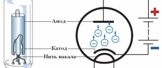
- Vacuum (kenotrons), built on the principle of a lamp having 2 electrodes, where one of them is represented as an incandescent filament. In the slightly open position, the movement of electrons is from the pole to the minus. In the closed position, the movement path changes in the opposite direction or is suspended.
- Filled with gas (zener diodes with a smoldering or corona charge of ignitrons and gastrons). Of the voluminous list of elements, the most popular are gastrons with an arc charge (zener diodes). An inert gas is pumped inside them and oxide thermal cathodes are placed. The key feature of such LEDs is the ability to produce high output voltage and the ability to operate with voltage, the value of which can reach several tens of amperes.
Important! The value of resistance in the closed position is directly related to the value of forward current. If it is high, then the resistance will be low.
Let's talk about the player
To remove the laser diode taken from the DVD-RW drive, you need to carefully disassemble the device. To do this, you need to understand drive devices. It is placed in a special metal heat-removing housing, which is additionally placed in another metal base. It depends on you whether it is worth removing the device from such a housing or not.
DVD-RW drive
You can also leave the radiator in the case and remove the base. This affects the quality of the heat sink, which is necessary for our laser installation. Some experts argue that when the LED supplies a non-pulse current, the created heat sink will not be enough for the carriage. This statement will be correct for certain drive models, as well as if it is necessary to obtain maximum power. DVD-RW has two laser diodes built into it. Of these, one is infrared and is used for recording and playing CDs. And the second one is red and is used for playing and recording DVDs. As you can see, if you wish, you can make two lasers with your own hands.
In such assemblies, you cannot simultaneously connect infrared and red diodes if the current is large.
Types of diodes
The main division of diodes occurs according to their type. There are three categories: material of manufacture, pn junction area and purpose.
To produce diodes, one of four initial semiconductors is used:
- germanium - in low-power and precision circuits, has a higher transmission coefficient;
- silicon – inexpensive and durable, resistant to temperature, but less conductive;
- gallium arsenide – more expensive and more complex than silicon, high radiation resistance;
- indium phosphide - in LEDs and for operation at ultrahigh frequencies.
Each material in different systems has its own letter or number, which is indicated at the beginning.
There are two options for the structural placement of the cathode and anode:
- Point diode. One of the electrodes in the form of a narrow needle is fused into the crystal, forming a pn boundary. It has a small area, which results in a high operating frequency. They are almost out of use due to low strength, vulnerability to overloads and low maximum current.
- Planar diode. The transition area is larger - the contact passes over the area of the semiconductor wafer connected to the crystal. They are distinguished by higher capacity, low noise level, and low voltage drop. An example is a Schottky diode.
In modern marking, separation practically does not occur - planar diodes are gradually replacing point diodes.
The following designation depends on the purpose of the device. There is a classification of diodes used in different areas: tunnel, laser, varicaps, zener diodes. There is also a division within the subtype, based on technical parameters:
- operating frequency;
- recovery time;
- forward and reverse current;
- permissible values of reverse and forward voltage;
- temperature regime.
We recommend reading: Stabilizer AMS1117-3
This results in a large number of possible combinations, hence the difficulty of creating a unified labeling system.
Marking
In order to determine the type and find out the characteristics of a semiconductor diode, manufacturers apply special designations to the element body. It consists of four parts.
In the first place is a letter or number indicating the material from which the diode is made. Can take the following values:
- G (1) - germanium;
- K (2) - silicon;
- A (3) - gallium arsenide;
- And (4) - indium.
On the second - diode types. They can also have different meanings:
- D - rectifier;
- B - varicap;
- A - ultra-high frequency;
- I - tunnel;
- C - zener diodes;
- C - rectifying posts and blocks.
In third place is a number indicating the area of application of the element.
The fourth place is numbers from 01 to 99, indicating the serial number of the development.
Additional markings may also be applied to the body. But, as a rule, they are used in specialized devices and circuits.
For ease of perception, diodes can also be marked with various graphic symbols, for example, dots and stripes. There is no particular logic in such drawings. That is, to determine what kind of diode it is, you will have to look at a special correspondence table.
Device
Below is a detailed description of the diode structure; studying this information is necessary for further understanding of the principles of operation of these elements:
- The housing is a vacuum cylinder that can be made of glass, metal or durable ceramic varieties of material.
- There are 2 electrodes inside the cylinder. The first is a heated cathode, which is designed to ensure the process of electron emission. The simplest cathode in design is a filament with a small diameter, which heats up during operation, but today indirectly heated electrodes are more common. They are cylinders made of metal and have a special active layer capable of emitting electrons.
- Inside the cathode-indirect glow there is a specific element - a wire that glows under the influence of electric current, it is called a heater.
- The second electrode is the anode, it is needed to receive the electrons that were released by the cathode. To do this, it must have a potential that is positive relative to the second electrode. In most cases, the anode is also cylindrical.
- Both electrodes of vacuum devices are completely identical to the emitter and base of the semiconductor variety of elements.
- Silicon or germanium is most often used to make a diode crystal. One of its parts is p-type electrically conductive and has a deficiency of electrons, which is formed by an artificial method. The opposite side of the crystal also has conductivity, but it is n-type and has an excess of electrons. There is a boundary between the two regions, which is called a pn junction.
Such features of the internal structure give diodes their main property - the ability to conduct electric current in only one direction.
Main conclusions
Infrared LEDs emit in a region of the spectrum invisible to the human eye, and therefore, to indicate their main parameters, characteristics that are slightly different from conventional ice elements are used:
- Power over a period of time or from a specific emitter area.
- Intensity within a certain spatial angle.
There are dozens of modifications of infrared LEDs. They all differ not only in radiation strength, but also in purpose and form factor. The more powerful the ice crystal, the more it heats up and collapses. Therefore, when producing powerful models, manufacturers resort to some tricks, rather than taking the path of directly increasing their size. The scope of application of IR diodes is extensive - from indications in remote controls of household appliances to complex military-industrial and medical devices.
Previous LEDsTypes and varieties of connectors for LED strip Next LEDsTypes, features and circuit of IR illumination
Direct diode connection
The pn junction of the diode can be affected by voltage supplied from external sources. Indicators such as magnitude and polarity will affect its behavior and the electrical current conducted through it.
Below we consider in detail the option in which the positive pole is connected to the p-type region, and the negative pole to the n-type region. In this case, direct switching will occur:
- Under the influence of voltage from an external source, an electric field will be formed in the pn junction, and its direction will be opposite to the internal diffusion field.
- The field voltage will decrease significantly, which will cause a sharp narrowing of the blocking layer.
- Under the influence of these processes, a significant number of electrons will be able to freely move from the p-region to the n-region, as well as in the opposite direction.
- The drift current indicators during this process remain the same, since they directly depend only on the number of minority charged carriers located in the pn junction region.
- Electrons have an increased level of diffusion, which leads to the injection of minority carriers. In other words, in the n-region there will be an increase in the number of holes, and in the p-region an increased concentration of electrons will be recorded.
- The lack of equilibrium and an increased number of minority carriers causes them to go deep into the semiconductor and mix with its structure, which ultimately leads to the destruction of its electrical neutrality properties.
- In this case, the semiconductor is able to restore its neutral state, this occurs due to the receipt of charges from a connected external source, which contributes to the appearance of direct current in the external electrical circuit.
Usage
Semiconductor diode, a two-electrode electronic device based on a semiconductor (SC) crystal. The concept of "P. d." combines various devices with different principles of operation, having a variety of purposes. The classification system for semiconductor devices corresponds to the general classification system for semiconductor devices. The most common class of electrical transformer diodes includes: rectifier diodes, pulse diodes, zener diodes, and microwave diodes (including video detectors, mixing detectors, parametric detectors, amplifier and generator diodes, multipliers, and switching detectors). Among optoelectronic devices, photodiodes, light-emitting diodes, and PP quantum generators are distinguished.
The most numerous are PDs, the action of which is based on the use of the properties of the electron-hole transition (p-n junction). If a voltage is applied to the p-n junction of the diode (Fig. 1) in the forward direction (the so-called forward bias), i.e., a positive potential is applied to its p-region, then the potential barrier corresponding to the junction decreases and begins intense injection of holes from the p-region into the n-region and electrons from the n-region into the p-region - a large forward current flows (Fig. 2). If a voltage is applied in the opposite direction (reverse bias), the potential barrier rises and only a very small minority carrier current flows through the pn junction (reverse current). In Fig. Figure 3 shows an equivalent circuit of such a P.D.
The operation of rectifier (power) diodes is based on the sharp asymmetry of the current-voltage characteristic (VC). For rectifier devices and other high-current electrical circuits, rectifier power supply units are produced that have a permissible rectified current Iv of up to 300 A and a maximum permissible reverse voltage U*rev from 20-30 V to 1-2 kV. Pds of similar application for low-current circuits have Iв < 0.1 a and are called universal.
At voltages exceeding U*o6p, the current increases sharply, and an irreversible (thermal) breakdown of the p-n junction occurs, leading to the failure of the p-n junction. In order to increase U*rev to several tens of kV, rectifier columns are used, in which several identical rectifier P.D. are connected in series and mounted in a common plastic housing. The inertia of rectifier diodes, due to the fact that the lifetime of the injected holes is > 10-5-10-4 sec, limits the frequency limit of their use (usually to the frequency range 50-2000 Hz). The use of special technological methods (mainly the doping of germanium and silicon with gold) made it possible to reduce the switching time to 10–7–10–10 sec and to create high-speed pulsed pulse generators, which are used, along with diode matrices, mainly in low-current signal circuits of computers.
It will be interesting A few facts about the laser diode
Diode reverse connection
Now we will consider another method of switching on, during which the polarity of the external source from which the voltage is transmitted changes:
- The main difference from direct connection is that the created electric field will have a direction that completely coincides with the direction of the internal diffusion field. Accordingly, the barrier layer will no longer narrow, but, on the contrary, expand.
- The field located in the pn junction will have an accelerating effect on a number of minority charge carriers, for this reason, the drift current indicators will remain unchanged. It will determine the parameters of the resulting current that passes through the pn junction.
- As the reverse voltage increases, the electric current flowing through the junction will tend to reach its maximum. It has a special name - saturation current.
- In accordance with the exponential law, with a gradual increase in temperature, the saturation current indicators will also increase.
Tube intro
Lamps were previously widely used in circuit design; the first electronic devices were built using them. The golden age of radio tubes was in the first half of the 20th century. For our grandfathers and great-grandfathers, giant computers that occupied an entire room and basked like hell were much more familiar. You can't watch a TV series on a car like this.
Then there was a time when Soviet microcircuits became the largest in the world. But this is another story, which began after the advent of semiconductor devices. As you understand, this article is about the operation of a vacuum tube and its modern use.
How does a diode work?
You may not physically see the diodes themselves, but the result of their action surrounds us everywhere. These devices allow you to control the flow of current in a specified direction. There are many different versions of diodes. In what cases is this necessary? Below we will discuss examples and, to some extent, the operating principle of semiconductor diodes. If you add two metal plates to the P and N working areas of the material, you get anode and cathode electrodes. The scheme for connecting the electrodes to the source can work as follows: applying voltage from the battery to the N electrode ensures the attraction of positrons, respectively, to the P electrode – electrons; the absence of tension returns everything to its original state; changing the polarity of the applied voltage ensures the attraction of electrons in the opposite direction to the positive plate, and positrons to the negative one. In the latter case, excess charges accumulate on the metal plates, while a dead insulating zone is formed in the center of the material itself.
Thus, the central section of the material becomes a dielectric. The device does not pass current in this direction. The word comes from di (double) + -ode. The definition of the terms cathode and anode of a diode related to contacts is known to every person. The cathode is the negative electrode, the anode is the positive electrode. If you apply plus to the anode and minus to the cathode, the diode will open and electric current will flow through it. Thus, a diode is a device that has two electrodes: a cathode and an anode. A simple nonlinear electronic device consisting of two different semiconductors. How the diode works is clearly visible in the image.
We recommend reading: The simplest 220 volts without a driver (the simplest way to power an LED from a 220V network)
Types of diodes.
Principle of operation
The easiest way to explain the principle of operation of rectifier diodes is with an example. To do this, we simulate the circuit of a simple half-wave rectifier (see 1 in Fig. 6), in which power comes from an alternating current source with voltage UIN (graph 2) and goes through VD to the load R.
Rice. 6. Operating principle of a single-diode rectifier
During the positive half-cycle, the diode is in the open position and passes current through it to the load. When the turn of the negative half-cycle comes, the device is locked and no power is supplied to the load. That is, there is a kind of cutting off of the negative half-wave (in fact, this is not entirely true, since during this process there is always a reverse current, its value is determined by the Irev characteristic).
As a result, as can be seen from graph (3), at the output we receive pulses consisting of positive half-cycles, that is, direct current. This is the principle of operation of rectifying semiconductor elements.
The disadvantages of a single-diode rectifier include:
- Low level of efficiency, since negative half-cycles are cut off, the efficiency of the device does not exceed 50%.
- The output voltage is approximately half that of the input.
- High noise level, which manifests itself in the form of a characteristic hum at the frequency of the supply network. Its reason is asymmetrical demagnetization of the step-down transformer (in fact, this is why for such circuits it is better to use a damping capacitor, which also has its negative sides).
Note that these disadvantages can be somewhat reduced; to do this, it is enough to make a simple filter based on a high-capacity electrolyte (1 in Fig. 7).
Rice. 7. Even a simple filter can significantly reduce ripple
The operating principle of such a filter is quite simple. The electrolyte is charged during the positive half-cycle and discharged when the negative half-cycle occurs. The capacitance must be sufficient to maintain the voltage across the load. In this case, the pulses will be somewhat smoothed out, approximately as shown in graph (2).
The above solution will improve the situation somewhat, but not much; if you power, for example, active computer speakers from such a half-wave rectifier, a characteristic background will be heard in them. To fix the problem, a more radical solution will be required, namely a diode bridge. Let's look at the operating principle of this circuit.
Possible faults
During operation of devices with diodes, various breakdowns can occur. This occurs due to aging of the elements or their depreciation.
Repair specialists distinguish 4 types of faults.
Among them are:
- Electrical breakdown. This is one of the most common failures that occur with diodes. It is reversible, since it does not lead to destruction of the diode crystal. This can be corrected by gradually reducing the supplied voltage.
- Thermal breakdown. Such a malfunction is more destructive for the diode. It occurs due to poor heat dissipation or overheating in the pn junction region. The latter is formed only if the device is powered by a current with excessively high rates. Without repairs, the problem will only get worse. In this case, the vibrations of the atoms of the diode crystal will increase, which will lead to its deformation and destruction.
- Break. When this malfunction occurs, the device stops flowing electrical current in both directions. Thus, it becomes an isolator blocking the entire system. To eliminate a breakdown, you need to accurately determine its location. To do this, special highly sensitive testers should be used, which will increase the chance of detecting a break.
- A leak. This breakdown is understood as a violation of the integrity of the housing caused by physical or other impact on the device.
The diode is an important design element that ensures proper and uninterrupted operation of the device. By choosing this element correctly and ensuring optimal operating conditions, you can avoid any malfunctions.
Driver classification
At the moment, there are two main types of drivers that can be connected to our semiconductor:
pulse driver. It is a special case of a pulse voltage converter. It can be either downward or upward. Their input power is approximately equal to the output power. In this case, there is a slight conversion of energy into heat. A simplified pulse driver circuit looks like this;
Simplified switching driver circuit
linear driver. The circuit typically supplies more voltage to such a driver than the semiconductor requires. To extinguish it, a transistor is needed, which will release excess energy with heat. Such a driver has low efficiency, and therefore is used extremely rarely.
Line Driver Circuit
Due to the fact that any laser diode can be powered through two different types of drivers, the connection diagram will be different.
Application area
The scope of use of these parts in modern radio engineering is high. It is difficult to find a device that works without these parts. To understand why a diode is needed, here are a few examples:
- Diode bridges - contain from 4 to 12 semiconductor devices that are connected to each other. The main task of diode bridges is to rectify current, and they are actively used, for example, in creating generators for cars.
- Detectors - created by combining diodes and capacitors. As a result, it becomes possible to isolate low-frequency modulation from various signals. Used in the manufacture of radio and television receivers.
- Protective devices - allow you to protect the electrical circuit from possible overloads. Several products are connected in the opposite direction. When the circuit is working normally, they remain in the closed position. As soon as the input voltage reaches critical levels, the device is activated.
- Switches - such systems based on these products allow switching high-frequency signals.
- Spark protection systems - the creation of a shunt-diode barrier allows you to limit the voltage in the electrical circuit. To increase the degree of protection, special current-limiting resistors are used together with semiconductor parts.
These are just a few examples of the use of diodes. They are quite reliable devices that can be used to solve a large number of problems. Most often, these radio components fail due to natural aging or overheating.
If an electrical breakdown of a product occurs, its consequences are rarely irreversible, since the crystal is not destroyed.
First build option
In this situation, it is necessary to use the following scheme for assembling a device based on a laser diode removed from the DVD-RW drive.
Assembly diagram
The disadvantage of this scheme is the presence of a situation where the battery voltage sags at the time of discharge, which causes a linear drop in the laser brightness level. To assemble a laser system according to the above diagram, you need not only a diode, but also capacitors with any voltage (from 3V). In the diagram they are marked with the icon C1 and C2. The capacity of the first capacitor should be 0.1 µF, and the second - 100 µF. They will protect the diode from static electricity and also ensure a smooth transition of processes. Once the capacitors have been connected to the laser light source, the wire can be removed from the lead. When connected to a diode, one of the terminals on the housing will supply a minus. At the same time, the second conclusion will be a plus, and the third one will not apply. The location of the pluses is shown quite well in the second diagram, which will be described below. It is worth knowing that a plus is supplied to the body of some diodes (for example, 808nm LED). Dual models are characterized by the presence of a middle terminal for the common negative (G), and an outer terminal - C for powering DVD, CD, D. Such a circuit can be powered from a mobile battery or 3 AA batteries.
In this case, the current can also have different values. For example, at the appropriate write speeds of a DVD-RW drive, the laser diode can have the following values of parameters such as power and current:
- at speed 16, the power will be 200 mW, and the current will be 250-260 mA;
- at speed 18, the power will be 200 mW, and the current will be 300-350 mA;
- at speed 20, the power will be 270 mW, and the current will be 400-450 mA;
- at speed 22, the power will be 300 mW, and the current will be 450-500 mA;
- at speed 24 the power will be 300mW and the current will be 450-500mA.
Infrared diode
The infrared diode of the CD-RW drive will have a power of 100-200 mW. For comparison, violet in BLU-RAY RW is from 60 to 150 mW, and in non-recording models -15 mW. Before assembling this circuit, when using a DVD drive laser diode, you need to find out what resistance is required for resistor R1. To do this, you can use the formula R1=(Uin.-Ufall.)/I, in which:
- Uin. – voltage coming from the battery;
- Upd. is the voltage drop that the diode receives. The red diode should have approximately U drop. equal to 3 V. This voltage is suitable for a low-power non-writing DVD drive. For infrared diode Upad. will be approximately 1.9 V, and for violet or blue - 5.5 V and 4-4.4 V, respectively;
- I is the current strength. It can be found out from a special table.
When assembling a laser, many experts recommend using resistors with a higher resistance than what was obtained in the calculations. This will protect the semiconductor from excessive current. Using a multimeter, you can further reduce the resistance.
Rectification factor
Analyzing the device characteristics, it should be noted: such quantities as the rectification coefficient, resistance, and capacitance of the device are taken into account. These are differential parameters.
It reflects the quality of the rectifier.
It can be calculated: it will be equal to the ratio of the forward current of the device to the reverse one. This calculation is acceptable for an ideal device. The value of the rectification coefficient can reach several hundred thousand. The larger it is, the better the straightener does its job.
Basics of electronic emission.
Vacuum tubes use flows of free electrons in a vacuum. Therefore, it is necessary to obtain a sufficient amount of free electrons in each vacuum tube. The phenomenon of the release of free electrons from the surface of certain substances is called electron emission.
The emission of electrons under the influence of heat is called thermionic emission. Other types of emission include: electrostatic or field emission - the ejection of electrons by a strong electric field, secondary electron emission - the knocking out of electrons by impacts of fast moving electrons, electron emission under impacts of ions, photoelectron emission - the release of electrons under the influence of light rays.