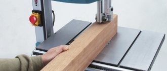
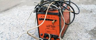
Welding rectifier Blueweld Combi 4.135 Turbo
The main structural unit of the welding machine is the power source . The characteristics of this element serve as the basis for the classification of welding installations. The following main types are distinguished:
- transformers;
- rectifiers;
- inverters;
- generator sets running on diesel or gasoline fuel.
Here we will dwell in detail on the features of rectifiers.
*
The device, what it consists of
Welding rectifier Telwin LINEAR 410 S
The welding rectifier consists of the following components and blocks:
- power transformer. In design and principle of operation, it is similar to a transformer for alternating current welding;
- rectifier unit on semiconductor devices. To convert alternating current into direct current, semiconductor elements are used: uncontrolled valves - silicon diodes;
- controlled valves - thyristors;
It is advisable to use a three-phase rectifier , i.e., equipped with a three-phase transformer. In this case, the ripple of the rectified voltage will be significantly lower, which increases the efficiency of the welding device and improves the quality of the weld.
Maintenance and repair
In order for a welding rectifier to work well, it is necessary to carry out proper maintenance of the device and timely repairs. The first includes checking all conductive parts for the integrity of the insulation, the reliability of the terminals, and the removal of dust from the internal elements. Before putting into operation the device must be grounded. The screw for adjusting the stroke of the secondary winding must be periodically lubricated. Do not operate the straightener without a protective cover.
The most common breakdowns are overheating and strong noise of the device. If these symptoms are observed, this may mean:
- the fan impeller does not meet the required size and needs to be replaced;
- the cooling fan shaft is jammed;
- the primary winding of the transformer has short-circuited and needs to be rewound;
- the insulation of the core sheets or its studs is broken.
Other common rectifier failures requiring repair include a decrease in output voltage. This could be due to a short or break in the secondary winding. If the magnetic starter turns on for one second and turns off, then the reason lies in a non-working diode, or a short circuit of the current to the casing of the device.
The straightener allows you to carry out welding work to obtain better quality seams on various metals. Thanks to the conversion of current from the transformer into constant voltage, welding and cutting with a stable arc is possible, and consumables are saved.
Principle of operation
One of the elements of the rectifier device is a step-down transformer with three windings and a control unit. The most common rectification circuits are single-phase and three-phase bridge, with a full-wave rectifier. The three-phase bridge circuit ensures uniform loading of all phases of the power network and greater arc stability with fewer valves.
When using this circuit, at a certain point in time, two elements connected in series with the load conduct current; in one period exactly six pulsations of electric current occur. Thus, the arc is powered by a direct, rectified current flowing through the secondary winding circuit.
Mini welding transformer
If you do not need to weld rails or channels from 4–5 mm steel, you can assemble a compact welder for soldering steel wire (making frames for homemade products) or welding thin sheet metal. To do this, you can take a ready-made transformer from a powerful household appliance (the ideal option is a microwave) and rewind the secondary winding. Wire cross-section 15–20 mm², power consumption no more than 2–3 kW.
The calculation of the circuit is carried out in the same way as for more powerful units. When assembling the rectifier, you can use less powerful diodes.
Purpose
The welding rectifier is a device designed for steel and metal structures; an energy source for the welding arc, using semiconductor elements that converts the alternating current of the network into a direct welding current that does not change its direction and magnitude.
Welding rectifier Brima VDM 1203 (380 V). Photo Welding Technologies
What it is?
This device consists of several semiconductor blocks that rectify the current to a value sufficient to carry out work. Like any other welding equipment, the rectifier has two contacts - positive and negative .
One is mounted on the workpiece, the second is equipped with a torch or electrode holder. The polarity of the work depends on the type of rectifier and the required operating mode.
The connection occurs due to the initiation of a welding arc between the electrode and the surface to be connected.
What type of welding are they used for?
Most welding technologies are produced using this equipment. These include MMA (manual arc welding with a coated electrode), MIG (fusion gas welding), TIG (non-consumable electrode argon arc welding). The use of rectifiers makes it possible to weld not only ferrous metals, but also stainless, heat-resistant and heat-resistant high-alloy steels, cast irons, non-ferrous metals, aluminum and titanium alloys.
What electrodes are used
Welding can be done with any type of electrode:
- DC welding electrodes (for example: UONII-13/55 or UONI-13/55);
- universal electrodes (for example: ANO-4, MR-3 or OZS-12);
- special electrodes.
Design of transformer and chokes
Wire winding diagram.
T1 is assembled from 3 “lines” from old TVs, folded together. Core PK30x16 made of ferrite grade 3000NMS-1. Windings “I” and “II” each have 2 sections with PSD 1.68 wire insulated with fiberglass. They are connected in series and have turns:
- winding “I” - 2×4;
- winding “II” - 2×2.
Winding “I” operates in the worst thermal conditions, so during assembly it is necessary to wind it with a pitch (gap) of 1 mm. In the second winding, do not forget to tap from the middle.
Both windings must be placed in such a way that the operation of the diodes VD11-VD34 is not disrupted. The winding direction of winding “I”, starting from the terminal connected to L2, is counterclockwise. And the winding direction of winding “II” is clockwise, from the terminal connected to VD21-VD34.
Winding “III” is a turn of wire 0.4-0.5 mm in insulation for a voltage of 500 V or more.
It is important to distribute the windings, maintaining the gaps correctly. This is necessary for cooling the magnetic circuit and for safety reasons. To do this, install 4 fiberglass (1.5 mm) plates, which are glued after adjustment.
Inductor L1, with an inductance of 40±10 μH, is wound on a PL core 12.5×25-50 with a gap (non-magnetic) of 0.3-0.5 mm and has 175 turns wound with PEV-2 type wire, caliber 1.32.
Choke L2 is a spiral without a frame, wound with 4 mm2 wire in thermal insulation. Number of turns -11, winding diameter -14 mm. A large current flows through the inductor and it needs to be blown through.
Differences and advantages of DC welding
Arc welding of steels
Welding with direct current has a number of advantages compared to a similar process with alternating current:
- The welding arc burns stably; the improvement of this indicator is influenced by the absence of zero instantaneous welding current values;
- the depth of penetration has been increased ;
- metal is splashed significantly and losses are reduced;
- the strength of the weld is much higher;
- the number of seam defects is reduced.
Differences from AC devices
The operation of a classic welding transformer is accompanied by a strong pulsation of the rectified current. This negatively affects the quality of the connection, which contains a large number of defects. In addition, welding with a transformer is accompanied by a large amount of melt spatter, which leads to excessive consumption of filler materials. Rectifiers for arc welding are free from this drawback , thanks to the above-mentioned blocks. The welding current is more stable, improving the quality of the seam.
Some welders mistakenly believe that it is preferable to use a transformer when deep welding. However, research shows that the use of a rectifier only improves the quality characteristics of the connection.
Where is the equipment used?
The advantages of DC welding over AC welding allow its use when making critical connections. It is used when welding the following metals:
- heat-resistant, high-alloy, low-carbon, corrosion-resistant steels;
- titanium;
- cast iron;
- alloys based on copper and nickel and much more.
DC welding is widely used in all areas of industry, in large enterprises, construction sites, small workshops, among home craftsmen in country houses and garages.
Calculation of the number of turns
The number of layers for each winding is determined from the core area using the formula K = 50: Sc = 50/45 = 1.11 turns per volt.
Attention! In this formula, as well as in the first, the coefficient of 50 is adopted for transformers with cores of types P and Sh., for ring cores it will be equal to 35 for, ShL and ShP - 40.
Now we determine the maximum current on the primary winding using the formula: Imax = P: U = 6750: 220 = 30.71 A. Based on these data, you can find out the number of layers for winding. The calculation is carried out using the formula Wx = Ux * K. For the secondary, it will be W2 = U2 x K = 60 x 1.11 = 67 turns.
We will find out the number of layers of the primary winding later because To do this, you need to apply a different formula. To adjust the output power, several outputs are made from the primary winding. The number of turns for the primary winding is found by the formula: W1st = (U1 x W2): Ust, vit.
Where:
- Ust – voltage on the secondary winding.
- U1 – voltage of the primary winding;
- W2 – number of turns of the secondary winding;
- W1st – the number of primary windings of a certain stage.
But first it is necessary to calculate the voltage of each stage Ust. To do this, we use the formula U=P: I, B.
Using the formula U = P: I, V. for the original design transformer P = 6750 W, we calculate the data for four stages with a power of 95 A, 110 A, 135 A and 165 A. Substituting the data into the formula, we obtain U1st1 = 6750:95 = 71 V, U1st2=61 V, U1st3=50 V, U1st4=41 V.
Next, we use the obtained data to calculate the winding. According to the formula W1st = (U1 x W2): Ust, vit. we get the number of turns for each stage (rounded up) W1st1 = (220x67): 71 = 208 turns, W1st2 = 242 W1st3 = 295 turns, W1st4 = 359 turns.
By adding a value of 6% to the larger number of turns, we obtain the required calculated total number of turns of the primary winding W1 = 359 + 18 = 377.
Finally, let's calculate the cross-section of the wire on the primary and secondary windings. To do this, divide the maximum current for each winding by the current density. As a result of the calculation: Ssecond = 165: 3 = 55 mm2, Sfirst = 11 mm2.
As a result, the calculation of a welding transformer powered from a single-phase network U1 = 220V, with a power of 6.75 kW. we get:
Iron: U-shaped stamped sheets of transformer steel 0.5 mm thick Type of windings - circular wound on a frame; Number of turns W1 = 377 V., W2 = 67 V., Number of adjustable steps - 4. at Ireg - 95 A, 110 A, 135 A and 165 A. Wire cross-section Ssecond = 55 mm2, Sfirst = 11 mm2
Advantages and characteristics over transformer devices
Unlike transformers, rectifiers provide much more powerful energy indicators , have a wider range of control limits, they are much simpler and more reliable to use , have less weight and dimensions, are more economical in manufacturing, and, what is undoubtedly pleasant, they are almost silent . Since the current flows continuously, the depth of metal penetration increases, welding proceeds stably, and the strength and quality of the seam increase.
Welding rectifier SiMZ VD-306 ST. Photo 220Volt
Classification by type: multi-post, single-post and others
There are several types of welding rectifiers.
Welding station is a welder’s workplace. Rectifiers have designs that can serve both one post and several at the same time. If everything is clear with one post, then how a group of posts functions without influencing each other needs to be explained.
Welding 4-station rectifier VDM-6303S. Photo VseInstruments.ru
Independence in operation is determined by the constant open circuit voltage of each post . This is ensured by a rigid current-voltage characteristic. With a falling characteristic, a short circuit at a single station would reduce the voltage at other posts and stop welding. Each post has an additional variable resistance to regulate the current.
A multi-station welding rectifier is used in industrial settings . Single-station welders are used by non-professional welders.
Welding rectifier ETA VD-306 B 3x380. Photo VseInstruments.ru
The main property for classifying welding rectifiers is the difference in the characteristics of the output rectified voltage from the welding current. Depending on this characteristic ( flat, steep or universal ), the applicability of the rectifier to one or another welding technology is determined.
Steeply falling characteristic - for manual arc welding with coated piece electrodes, argon arc welding with tungsten electrodes, mechanized submerged arc welding on machines with regulation of the electrode wire feed depending on the arc voltage.
Rectifiers with a flat-sloping characteristic are used for mechanized welding with a consumable electrode in a shielding gas environment or submerged arc, at a constant wire feed speed, independent of the arc voltage. The manufacturer obtains these characteristics by adjusting the transformer, adjusting the inductive reactance of the inductor, or using semiconductor devices. First of all, it is important to know what kind of work the welding rectifier is suitable for and its parameters.
- Transformer. Moving coils are located inside the power transformer. Primary adjustment is made by switching the windings from a star to a delta circuit. Fine adjustment occurs by changing the distance between the windings.
- Transistor. A semiconductor operates on the switch principle. The transistor is configured for a certain current value. In this case, the regulation of the strong current occurs at the expense of the weaker one. This control method expands the range of applied welding currents.
- With saturation throttle adjustment. Typically, the inductor (inductive reactance) is located between the transformer and the rectifier unit. The power transformer produces constant voltage. The use of inductive reactance allows you to change the parameters and the rectifier will already operate on a falling current-voltage characteristic.
- Thyristor. Here the voltage and current are controlled using an electronic circuit. The circuit has a trimming element through which the voltage and current supplied to the electrode at the welding site are adjusted.
- Inverter welding rectifiers. The welding current is adjusted according to a completely different principle. Electronic devices are capable of autonomously regulating high-frequency welding current and avoiding increasing current by reducing voltage.
Inverter rectifier Battleship VD-201I. Photo Welding Technologies
Welding rectifiers are divided into household ones , with a power not exceeding 200 A, semi-professional (power up to 300 A) and professional (over 300 A). Models differ in power, size and amount of energy absorbed.
Welding inverter rectifier Foxweld VD-306I, maximum current – 315 A. Photo VseInstruments.ru
Basic technical data of rectifiers: supply voltage and no-load voltage, maximum operating power, power consumption, type of welding current, electrode diameter, weight and dimensions. Different types of rectifiers are designed for different jobs - for example, VD2-313 is used for two-station arc welding of steel objects, and VDU-506 is a universal rectifier, capable of completing automatic welding machines and powder welding.
Different types of rectifiers are designed for different jobs - for example, VD2-313 is designed for two-station arc welding of steel objects, and VDU-506 is a universal rectifier, capable of completing automatic welding machines and powder welding.
Advantages and disadvantages
The advantages of rectifier welding machines mainly lie in the high reliability of the unit. The device can be used in almost any conditions, even if there is dirt, dust and other “enemies” around that can destroy the inverter in one or two minutes. You can also perform complex welding work using the rectifier. For example, welding stainless steel or non-ferrous metal.
With skillful ignition, the arc burns very stably and allows you to make a neat seam. The rectifier can also be used for most common welding technologies, ranging from MMA to TIG, MIG, MAG technologies. Another important advantage is the ability to organize several welding stations from one machine at once. This means that several people can cook at once using just one straightener. Such a device is called a multi-station welding rectifier and is used in production. Such a device also has disadvantages, and sometimes they are critical. The first thing you need to know is that the straightener is very heavy and clumsy. You won’t be able to throw it into the trunk and take it to the dacha alone. There may also be difficulties in transporting the device to the construction site.
Another disadvantage is the high cost of the equipment set. The rectifier itself is not very expensive, but the accompanying equipment may not be affordable. However, we will talk about this in more detail below. Also keep in mind that the rectifier consumes a lot of electricity, and you may not be prepared for large bills.
The last minus, which can be called a plus at the same time, is the need for high qualifications to form a high-quality seam. If you are a beginner, be prepared for years of constant practice. On the other hand, if you learn how to cook with a straightener, then after that you will be able to cook with anything. And this is an undoubted advantage.
Adjusting the welding current
The welding current in the rectifier is adjusted using electromechanical or electrical methods. Electromechanical adjustment of welding current involves performing this operation before the rectifier unit . In this case, the rectifying valves are supplied with alternating current, which already has the parameters required for welding. Electrical adjustment is possible on rectifiers equipped with thyristors, and consists of changing the angle of their adjustment.
Installation
When using a parallel circuit for connecting diode bridges, it is necessary to take into account that they all have some variation in parameters.
Therefore, when selecting elements, it is necessary to do this with some margin of safety. If this requirement is met, a more compact diode bridge can be obtained for the welding machine than when using single diodes.
Diode assemblies allow them to be placed on one radiator, since the cases are not energized. This allows you to install them anywhere, even outside.
Depending on the required welding current, the rectifier may require 3 to 5 diode assemblies. For better heat transfer, diode bridges are installed on the radiator through heat-conducting paste.
It is recommended to connect conductors to the contacts by soldering, otherwise there may be power losses at the contact point and its strong heating.
How to connect a ballast, ballast rheostat
Ballast rheostat (ballast) is a circuit device with a welding rectifier, with the help of which the welder adjusts the current. The regulation principle is based on the action of Ohm's law, known in electrical engineering. The higher the resistance that the ballast represents, the lower the current.
Ballast rheostat Ballast rheostat Brima RB-302. Photo VseInstruments.ru
Typically, a ballast is a spring, the efficiency of which depends on the optimally selected length of the spring, the diameter of the coils and wire, as well as the material from which it is made. A regulator contact is connected to the spring, moving it in the direction of winding changes its resistance, and therefore the current strength. The regulator contact is connected to the wire of the welding machine holder. The other end is connected to the power supply.
Features of use
The first thing you need to pay attention to if you want to use a rectifier at home is the voltage of your electrical network. It is unlikely that it exceeds 220V, and often the figure is even less. Of course, there are devices on sale that can operate on 220V voltage, but they are rare. Most rectifiers require 380V to operate fully. Such an electrical network is also called an industrial three-phase network. To solve this problem, you need to use a generator that produces 380V.
This is the main drawback of the rectifier. This is a powerful device that gives you a lot of possibilities, and at the same time it is not very expensive. But for it to work, you will have to buy an expensive generator and tinker with the connection every time. It is for this reason that many beginners prefer to buy a low-power inverter and plug it into an outlet, instead of struggling with a transformer or rectifier.
Also keep in mind that for stable operation it is not enough to simply connect the rectifier to 380V and start working. The rectifier (like the transformer) is very demanding on the electrical network itself. It should not only be stable, but also have a power reserve. This is necessary to ignite the arc and ensure its stable combustion.
Also keep in mind that it is not so easy to ignite an arc with a rectifier, even if everything is fine with the voltage in the network. The important thing here is to have the skill or just practice a lot. The rectifier is not equipped with additional functionality such as arc force or hot start. So you will have to light the arc based on your experience and skills.
With your own hands
Practice has shown that some people successfully cope with the independent production of welding rectifiers. The main thing is to develop a workable scheme . The main initial parameters will be the diameters of the electrodes with which the rectifier is designed to work. So, for example, if it is 3 mm, then the welding current must be provided at about 150 A, if it is 4 mm. – 200 A.
The diagram must indicate the parameters of the following elements:
- Transformer. It is advisable to select a circuit from ready-made devices. However, this condition is not easy to fulfill; you have to learn how to make a transformer yourself. Calculating its elements (core cross-section, number of turns on the windings and wire sizes) is not that complicated. Assembly and installation experience is quickly gained after one or two unsuccessful rewinds.
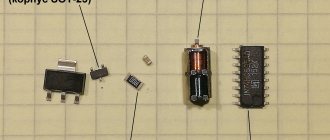
- Rectifier block. Voltage is supplied after the secondary winding of the transformer. The following elements are used for operation: diodes;
- capacitor;
- throttle.
The diodes are assembled using a bridge circuit. After it, the current is not alternating, but pulsating. This current is not suitable for welding, so there is a capacitor . It smoothes out pulsations . Finally, direct current is obtained using a choke. The inductor works as a filter , which passes the direct component of the current, and delays the variable.
Welding rectifier BLUE WELD KING TIG 200
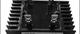
Diodes operating at such high currents generate a lot of heat. Therefore, they are necessarily included in the assembly complete with cooling radiators. It is important to consider forced airflow of the welding machine from a fan.
The capacitors for the welding unit are designed for the maximum ripple voltage. For the rectifier unit, they differ from those used in radio engineering, which do not work with pulsed currents.
Important! Pay close attention to the characteristics.
To make a choke, you need a core made of transformer iron and an insulated copper busbar (you can use a core twisted from tinned copper wires with insulation). The cores can be used from old radio equipment. The choke core and winding are assembled with a gap . After testing the device, the gap and number of turns in the winding can be adjusted.
- Welding rectifier base. The textolite plate has excellent insulating properties. It is not advisable to place devices on it close to each other. During operation, a large amount of heat is generated, so it is necessary to have a sufficiently large ventilated space.
There are many options for making a welding rectifier with your own hands. They will differ in design due to the way they are regulated. The contractor will develop his own design in relation to the specifics of the work performed.
Types of welding rectifiers
Current-generating welding converters are distinguished by design and method of adjusting power parameters.
Types of rectifiers:
- regulated by transformer;
- with a choke - an induction coil that restrains sudden voltage surges;
- with regulating thyristors that change the voltage;
- with transistors - semiconductors that smooth out pulse current surges;
- inverter - converters with a frequency increase in current and a regulator of its strength.
Classification of rectifiers according to the possibilities of adjusting current-voltage characteristics (a few words about the features of each device):
- Three-phase for manual electric arc welding. Bulky models with a transformer. The converter operates with large energy losses, the capabilities are limited by the power of the transformer by a metal or magnetic shunt - additional resistance.
- Automatic and semi-automatic machines. The power flow is regulated by the magnetic field. The rheostatic secondary winding allows you to change the number of turns - this is the principle of current-voltage regulation. An oscilloscope is installed for pulse adjustment. The current is first rectified, then transformed into high purity alternating current.
- Throttle three-phase rectifiers for arc and argon welding. They are equipped with an additional core with a winding that acts as a charge storage device supplied to the rectifying capacitor.
Brands, models
Welding rectifier BRIMA MIGSTAR-160
Popular models of welding rectifiers include:
- welding rectifier brand Telwin model LINEAR 410 /S. Parameters: 15000 W, 350 A.
- welding rectifier for argon arc welding brand Blue Weld KING model TIG 200 AC/DC-HF/Lift 832200.
- welding rectifier brand Blueweld model Combi 4.135 Turbo.
- welding rectifier brand BRIMA model MIGSTAR-160 .
A complete list of brands and models of equipment for DC welding is presented on the official websites of suppliers.