Stepper motors are widely used in modern industry and homemade products. They are used where it is necessary to ensure the accuracy of the positioning of mechanical components without resorting to feedback and precise measurements. Today I want to talk about a special type of stepper motors - miniature stepper motors, which are used in the design of optical systems. We will take a detailed look at their structure and how to control such tiny motors.
A stepper motor is a brushless electric motor with several windings (phases) located on the stator and magnets (often permanent) on the rotor. By applying voltage to the stator windings, we can fix the position of the rotor, and by applying voltage to the windings sequentially, we can move the rotor from one position to another (step), and this step has a fixed angular value.
We will not dwell on each type of stepper motor. Quite a lot has been written about this on the Internet, for example here.
I want to talk about a special type of stepper motors - miniature stepper motors, which are used in the design of optical systems. Such babies are available for free sale. But on the Internet, especially in Russian, there is very little information on such motors. Therefore, when I needed to use them in my project, I had to do a fair amount of searching for information and conduct a couple of experiments.
I will share the results of my searches and experiments in this article.
We will consider the issues of controlling such small motors, namely:
- L293D driver + ATtiny44 microcontroller;
- TMC2208 driver + ATtiny44 microcontroller;
- ATtiny44 microcontroller (without driver).
Actually, only the last point can raise questions here. Believe me, I was also surprised when I came across a video (here it is) where a guy simply takes and directly connects a stepper motor to the pins of a microcontroller! But let's talk about everything in order.
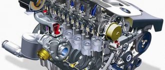
Design and principle of operation
Stepper motors are widely used in household appliances, vehicles, milling and grinding machines and other manufacturing machinery.
The device is a direct current motor, one revolution of which is divided into several identical steps (this is ensured thanks to the controller). Its main difference from other types of motors is the absence of a brush mechanism.
The stepper motor is equipped with a control unit (dashboard), transmitters and signaling devices.
What does a stepper motor consist of?
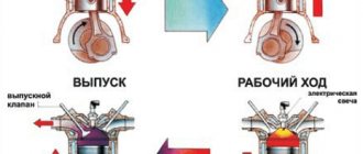
How does a stepper motor work?
Knowing the operating principle of a stepper motor, you can install or repair it yourself. It functions as follows:
- After voltage is applied to the terminals, continuous rotation of the special brushes begins. Input pulses set the drive shaft to a position that is predetermined.
- Under the influence of impulses, the shaft moves at a fixed angle.
- An external control circuit, most often represented by a microcontroller, excites gear-type electromagnets. One of them (the one to which energy is applied) attracts the gear teeth to itself, as a result of which the engine shaft turns.
- Once aligned with the leading electromagnet, the remaining magnets move towards the next magnetic part.
- The rotation of the gear is ensured by turning off the first electromagnet and turning on the next one.
- The gear is aligned with the previous wheel, after which the entire process is repeated as many times as necessary.
These rotations are a constant step. To determine the speed of the motor, you need to count the number of steps required to complete its revolution. Accuracy of operation is ensured thanks to microprocessor control systems for stepper motors.
Characteristics
From the point of view of mechanics and electrical engineering, a stepper motor is a very complex device that has many mechanical and electrical parameters. I will give a breakdown of the main technical parameters that are used in practice:
- The number of complete steps per revolution. The main parameter of the engine, which determines its accuracy, resolution, and smoothness of movement. On FL57 series engines this parameter is 200 and 400 steps per revolution.
- Full pitch angle. Representation in a different form of the previous parameter. Shows the angle the shaft will rotate during one full step. Can be counted as 360° / number of complete steps per revolution. For FL57 series engines it is 1.8° and 0.9°.
- Rated current. Main electrical parameter. The highest permissible current at which the electric motor can operate for an indefinitely long time. The mechanical parameters of the motor are specified for this current.
- Rated voltage. Permissible DC voltage on the motor winding in static mode. Often this parameter is not provided. Calculated according to Ohm's law through the rated current and winding resistance.
- Phase winding resistance. DC motor winding resistance. The parameter, together with the rated current, shows what voltage can be applied to the motor winding.
- Phase inductance. The parameter becomes important at significant rotation speeds. The rate of current rise in the winding depends on it. At high phase switching frequencies, it is necessary to increase the voltage so that the current increases faster.
- Torque. Main mechanical parameter. Shows the maximum torque that the engine is capable of producing. Sometimes a mechanical characteristic is given in the form of a dependence of torque on rotational speed.
- Rotor moment of inertia. Characterizes the mechanical inertia of the engine rotor. The smaller this parameter, the faster the engine accelerates.
- Holding moment. This is the torque when the engine is stopped. In this case, the motor must be powered by two phases with rated current.
- Stopping point. The torque required to turn the motor shaft when there is no supply voltage.
- Insulation resistance. Like all electrical devices, there is resistance between the body and the windings.
- Breakdown voltage. The minimum voltage at which insulation breakdown occurs between the windings and the housing. Parameter from the electrical safety section.
Scope of application
Stepper motors are widely used and are installed in many mechanisms.
Examples:
- Peripheral devices of computers.
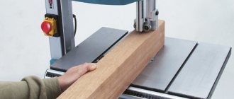
- Computer numerical control (CNC) machines: XY tables, milling machines, automatic drawing machines.
- Computer memory devices.
- Equipment for reading optical discs.
- Punch and tape reader, etc.
CNC milling machine
Two-phase hybrid stepper motors are actively used in mechanical engineering. They are also used in drives of various machines and mechanisms that operate in start-stop mode.
Stepper Motor Types
Main types of stepper motors:
• with variable magnetic resistance
• with permanent magnets
• hybrid.
Variable reluctance stepper motors
Variable reluctance motors do not have permanent magnets in the rotor. Their rotor is made of soft magnetic material and has a gear shape. The magnetic flux is closed through the teeth closest to the stator poles.
It will be interesting➡ What is an asynchronous motor and the principle of its operation
The teeth are attracted to the poles. This ensures rotation. For the same size, variable reluctance motors have less torque than other types of stepper motors. They are used quite rarely.
Permanent magnet motors
For stepper motors of this type, the rotor contains permanent magnets. The general operating principle of a stepper motor is identical to permanent magnet motors. Only in real engines there are more magnets. Here is an example of a motor with three pairs of rotor poles. In real permanent magnet motors the number of steps per revolution reaches 48, which corresponds to a step angle of 7.5°.
Hybrid engines
Hybrid motors provide smaller pitch, higher torque and higher speed. The number of steps per revolution for this type of motor reaches 400 (step angle 0.9°). At the same time, they are more difficult to manufacture and more expensive. I don't want to bog the reader down with the design of these engines. They have both a gear rotor and permanent magnets.
The operating principle of hybrid motors is equivalent to permanent magnet motors, but with a much larger number of poles. This is the most common type of stepper motor.
UNIPOLAR STEPPER MOTOR
Unipolar stepper motors, like bipolar ones, have two windings, and each of them has a central tap. Depending on the required direction of the magnetic field, the corresponding half of the winding is switched on, which is achieved by simply switching the keys and significantly simplifies the driver circuit.
This mechanism allows the use of a simple unipolar driver with four switches as a control system.
A unipolar two-phase stepper motor has six terminals. But it also happens that the middle taps of the coils are internally connected, which allows the stepper motor to have only five leads.
Due to their ease of operation, these motors are widely popular among both beginner hobbyists and many industrial sectors, since the unipolar stepper motor is the most primitive and cheapest way to obtain high-precision angular movements.
BIPOLAR STEPPER MOTORS
With bipolar stepper motors the situation is a little different. These motors have only one winding in one phase. The control circuit of a bipolar motor must be much more complex to change the direction of the magnetic field in order to change the direction of the current in the winding. This can be achieved using the H-bridge scheme. In addition, to simplify the task, you can purchase several driver chips that will help you.
Bipolar stepper motors, unlike unipolar ones, have two outputs per phase, neither of which is common. Static friction effects sometimes accompany the H-brigde, which occurs with certain drive topologies, but this can easily be corrected by smoothing the stepper motor signal at higher frequencies.
Unipolar stepper motors, unlike bipolar stepper motors, have two leads per phase, neither of which are common. Static friction effects sometimes accompany the H-brigde, which occurs with certain drive topologies, but this can easily be corrected by smoothing the stepper motor signal at higher frequencies.
LINEAR STEPPER SYNCHRONOUS MOTORS
In order to automate some production processes at an enterprise, sometimes it becomes necessary to move objects in a plane. To do this, you will need to use a special converter of rotational motion into translational motion, which is achieved by using kinematics.
Using linear stepper motors, it is possible to convert a pulse command directly into linear movement, which will significantly simplify the kinematic diagram of all kinds of electrical drives.
Schematic diagram of the operation of a linear stepper motor
The stator in this drive is presented in the form of a soft magnetic plate, and the wires are magnetized by the operation of a permanent magnet.
The tooth divisions in the stator and the moving part are the same, and they can be shifted by half a division within one rotor wire. The bias flux and its magnetic resistance, in this case, do not depend on where the moving part of the engine is located.
To move an object in a plane according to two coordinates, two-coordinate motors are used.
Linear motors also use magnetic air suspension. Due to the force of magnetic attraction, the rotor is attracted to the stator. Next, compressed air is pumped under the rotor through the nozzles, resulting in a force that pushes the rotor away from the stator.
This creates an air cushion between them and the rotor hangs above the stator with a minimum gap. This ensures a minimum resistance to rotor movement and high-precision positioning.
Acquaintance
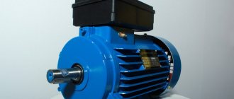
First, let's look a little at the appearance of our hero:
It's really very small! According to the smart book by Petrenko S.F. “Piezoelectric motors in instrument making”, it is in principle impossible to create smaller electromagnetic motors... that is, it is possible, but with a decrease in the diameter of the wire from which the windings are made, more and more energy is dissipated in the form of heat into the environment, which leads to a decrease in the efficiency of the motor and makes their use is irrational.
Of note, it can be noted that its shaft is very short and has a special groove for installing a gear or lever.
Two windings are clearly visible, which are even covered with insulation of different colors. This means that our motor most likely belongs to the class of bipolar stepper motors
. Let's see how it works:
I believe that our acquaintance with these motors will not be complete if we do not look at what is inside it. It's always interesting to look inside the mechanism! Is not it so?
Actually, we didn’t see anything unusual. The rotor is magnetized. There are no bearings anywhere, everything is on bushings. The rear bushing is pressed into the engine housing. The front one is not secured by anything. Interestingly, the engine housing was assembled by spot welding. So the front cover of the case had to be cut down.
Now let's move on to the issue of connection and its electrical characteristics.
Let's make sure it's bipolar by ringing the windings. Really bipolar, just like in the picture above. Winding resistance is about 26 Ohm
, although the seller indicated 14 Ohm.
The description says that the supply voltage is 5V
. Although you and I know that for a stepper motor the current that its windings will consume is important. Let's try to connect.
Connecting stepper motors
The choice of stepper motor connection diagram depends on:
- number of wires in the drive;
- way to start the mechanism.
It will be interesting➡ Little-known facts about DC motors
Existing engine models have 4, 5, 6 or 8 wires. A device with four wires can only be connected to bipolar devices. It is equipped with two phase windings, each of which has two wires. To connect the driver step by step, you need to identify pairs of wires with a continuous connection using a meter.
In a six-wire mechanism, each winding has two wires and a central tap. The engines of this model are characterized by high power and are connected to both bipolar and unipolar actuators.
In the first case, one center tap of each winding and one end of the wire are used.
In the second case, all six wires are used. The separation of the wire is carried out using a measuring device.
The difference between a five-wire motor and a six-wire model is that the center terminal connection is a solid cable that goes to the center wire.
Since separating one winding from another without breaking is not possible, it is necessary to determine the center of the wire, and then connect it to other conductors. This will be the safest and most effective solution. Then the engine is connected to the network and its functionality is checked.
To successfully operate the mechanism, you need to keep in mind the following nuances:
- The rated voltage is produced by the primary winding at constant current.
- The change in initial torque speed is directly proportional to the change in current.
- The rate at which linear torque decreases at subsequent high speeds depends on the inductance of the windings and the drive circuit.
Typical SD connection diagrams
Connection diagram of a 6-pin stepper motor to the GeckoDrive driver (bipolar serial connection of windings)
Connection diagram for an 8-pin stepper motor with bipolar parallel connection of windings to the GeckoDrive driver
Connection diagram for an 8-pin stepper motor with a bipolar serial connection of windings to the GeckoDrive driver
Stepper motor control
There are three stepper motor control modes:
• full step
• half-step
• microstepping.
Full step control mode
The first method was described in the examples above. This is alternating phase switching, the phases do not overlap, at any time only one phase is connected to the voltage source.
The method is called in English one phase on full step - one phase per full step. The rotor balance points coincide with the stator poles. The disadvantage of this mode is that at the same moment half of the windings are used for a bipolar motor, and only a quarter for a unipolar one.
There is a variant of a full-step control mode in which two phases are turned on at the same time. It's called two-phase-on full step - two phases per full step. With this method, the rotor is fixed between the stator poles by supplying power to all windings.
half-step mode
This allows you to increase engine torque by 40%. The pitch angle does not change, the rotor is simply shifted by half a step in equilibrium. This method allows you to get twice as many steps from the engine per rotor revolution.
Every second step one phase is turned on, and between them two phases are turned on at once.
As a result of such commutation, the angular movement of the step is reduced by half, or the number of steps is doubled. It is not possible to obtain full torque in half-step mode.
Despite this, the half-step mode is often used. Using very simple methods, it doubles the number of engine steps.
It must be remembered that for both modes it is true that when the engine is stopped and voltage is removed from all phases, the engine rotor is in a free state and can move due to mechanical influences.
microstepping mode
To fix the position of the rotor, it is necessary to generate a holding current in the motor windings. This current can be significantly less than the rated current.
The ability of the stepper motor to fix its position when stopping allows you to do without mechanical clamps, braking systems, etc.
Control of brushless motors
A controller is required to control a stepper motor. The controller is a circuit that supplies voltage to one of the stator coils. The controller is made on the basis of an integrated circuit of the ULN 2003 type, which includes a set of composite keys. Each switch has protective diodes at the output, which allow you to connect inductive loads without requiring additional protection.
An H-bridge system is used to control brushless motors. Which allows you to switch the polarity to reverse the stepper motor. It can be performed on transistors or microcircuits that create a logical chain for moving keys.
H-bridge diagram
As you can see, voltage is supplied to the bridge from the power source V. When contacts S1 – S4 or S3 – S2 are connected in pairs, current will flow through the motor windings. Which will cause rotation in one direction or another.
It will be interesting➡ Single-phase asynchronous motors in the service of humanity
With controller
The controller device allows you to control the stepper motor in various modes. The controller is based on an electronic unit that generates groups of signals and their sequence sent to the stator coils.
To prevent the possibility of damage in the event of a short circuit or other emergency situation on the motor itself, each terminal is protected by a diode, which will not allow a pulse to pass in the opposite direction.
Control Modes
Now let's look at different ways to supply current to the windings and see how the motor shaft rotates as a result.
Wave control or full step control of one winding
This method is described above and is called wave control of one winding. This means that only one winding has electrical current flowing through it. This method is rarely used. Basically, it is used to reduce energy consumption. This method allows you to obtain less than half the motor torque, therefore, the motor load cannot be significant.
This motor will have 4 steps per revolution, which is the nominal number of steps.
Full step control mode
The second and most commonly used method is the full step method. To implement this method, voltage is applied to the windings in pairs. Depending on the method of connecting the windings (series or parallel), the motor will require double the voltage or double the current to operate relative to that required when exciting one winding. In this case, the motor will produce 100% of the rated torque.
Such a motor has 4 steps per full revolution, which is the nominal number of steps for it.
Half-step mode
This is a very interesting way to get double the accuracy of a positioning system without changing anything in the hardware! To implement this method, all pairs of windings can be energized simultaneously, causing the rotor to turn half its normal pitch. This method can also be implemented using one or two windings. Below is how it works.
Single winding mode
Double winding mode
Using this method, the same motor will be able to produce twice the number of steps per revolution, which means double the precision for the positioning system. For example, this motor will give 8 steps per revolution!
Microstepping mode
Microstepping mode is the most commonly used method of controlling stepper motors today. The idea of a microstep is to supply power to the motor windings not with pulses, but with a signal resembling a sine wave in its shape. This method of changing position from one step to the next allows for smoother movement, making stepper motors widely used in applications such as positioning systems in CNC machines. In addition, the jerks of various parts connected to the motor, as well as the shocks of the motor itself, are significantly reduced. In microstepping mode, the stepper motor can rotate as smoothly as conventional DC motors.
The shape of the current flowing through the winding is similar to a sine wave. Digital waveforms may also be used. Here are some examples:
The microstepping method is actually a method of powering the motor, not a method of controlling the windings. Therefore, microstepping can be used in both wave control and full-step control mode. The following demonstrates how this method works:
Although microstepping appears to make the steps larger, this actually does not happen. Trapezoidal gears are often used to improve accuracy. This method is used to ensure smooth movement.
DIY stepper motor controller
The task is simple: using the ready-made circuit and program of Pavel Bakhtinov from this forum, lay out a printed circuit board, assemble and debug a controller for controlling stepper motors installed in the mount of an astronomical telescope. Next, you need to make a decent case and control panel.
It all starts with the details (Murphy’s law immediately comes to mind: “No talent could survive the passion for details”):
Working on the diagram:
We lay out the printed circuit board:
The photo template is ready:
Here I need to say a few words about my KNOW-HOW in making photo masks for transferring a design onto a printed circuit board.
Usually I print them on a printer - often on an inkjet, less often on a laser, because... The thermal film shrinks unexpectedly after heat treatment in the laser (and templates are needed for both sides), so it was impossible to align the two templates with sufficient accuracy (up to 0.15 mm).
The inkjet printer reproduces the dimensions well, but does not fill the paths with black densely enough; in some places they are still visible. A solution to this problem was soon found: we print not with pure black, but a little lighter towards yellow - the printer begins to add yellow (opaque to UV radiation) and tracks to the black ink, although they look more transparent, after photo transfer they turn out denser, practically without Izyanov.
The main thing is to choose the exposure:
The process of etching the printed circuit board is in progress:
Fully etched:
We drill holes with a diameter of 0.7mm to 1.5mm using a homemade drilling machine:
The soldering iron is old and remote:
We stuff the board with details:
All parts are sealed:
The reverse side of the board, the debugging process has begun:
This is how we will place the heating elements (those above in the figure on this side of the board are an integrated stabilizer and two microcircuits - motor drivers) on such beautiful radiators:
At this time, work has begun on the remote control. The main thing in the control panel, I think, is ergonomics, as far as it is appropriate to apply this to the box that will be obtained after assembly on domestic LARGE but reliable microbuttons.
... And so, after a long break, I continued working on this project again.
I played a little with different remote control design options and this is what I came up with:
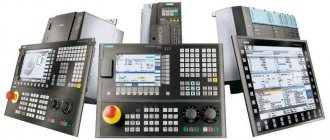
What are multi-axis controllers
In simple words, multi-axis controllers are modern devices with built-in microprocessors and an integrated programmable circuit.
They are small in size and easy to operate. They are used for precise positioning of units along two or more axes.
The main area of application is the automation of a machine stepper motor equipped with multi-axis electric drives. Their special feature is the support of multiple languages and the ability to manage online.
Controller Features:
- isolated digital inputs/outputs;
- high level of productivity;
- support for slave/master devices;
- option for remote control of the controller;
- interpolation support (circular, linear);
- a large set of digital and analog inputs/outputs, Internet ports and PWM outputs.
Popular models:
- PoKeys57CNC is a CNC controller with eight axes for Mach3 and Mach programs. Its feature is that it supports work via a USB and Ethernet interface. Standard STEP and DIR signals are used for control; up to eight stepper-type drivers are provided. The model is combined with encoders, a hand-held control panel, an LCD display, and limit switches. There are two relay and four transistor outputs, the ability to increase the number of outputs, Modbus TSP support, etc.
- Leadshine SMC6480 is a controller designed for microprocessor-based position control. Its structure includes a logical integrated circuit designed to send pulses, control the acceleration and deceleration process, and process inputs and outputs. The device is capable of reproducing pulses with a frequency of up to 5000 kHz and can withstand interpolation of up to four axes (linear) and up to two axes (circular). Individual analog and digital inputs/outputs, manual input and PWM output are provided.
Leadshine SMC6480 controller
In addition to multi-axis controllers, you can find other devices, for example, plasma heights. They monitor the presence of a working plasma arc and send a command to the main CNC board to move the torch.
Disadvantages and advantages of stepper motors
Advantages of stepper motors
• Precise positioning without feedback. The number of pulses determines the rotation angle.
• The motor delivers full torque at reduced speed until it stops.
• The motor fixes its position when stopped due to the holding current.
• Adjustment of rotation speed with high precision without feedback.
• Ability to quickly start, stop, reverse.
• High reliability. Lack of commutator brushes. Disadvantages of stepper motors.
• Complex control system.
• Low rotation speeds.
• Possible resonance phenomenon.
• Loss of positioning may occur due to mechanical overload.
• Low power density.
Let's try to find the cons
Like everything in the world, a stepper motor has certain advantages and disadvantages.
But there are areas in precision mechanics in which it is simply irreplaceable. Where you need to move mechanical components, instantly stop, move back, adjust the speed... Try to instantly stop a commutator motor, and you will forget about the shortcomings of a stepper motor.
Try to implement a change in the speed of the commutator motor within a wide range. It’s easier to install a stepper with its disadvantages.
Conclusion.
At the end of this voluminous article, I would like to express my gratitude to the sources from which we obtained information:
https://robotosha.ru
https://chipok.ru
https://ru.wikipedia.org
Closed and open-loop systems
Axis positioning systems allow intelligent controllers to position equipment with exceptional accuracy. A command is issued to move to the desired point in three-dimensional space and the machine responds very quickly and accurately.
Positioning systems typically use one of two methods: closed-loop and open-loop systems. So what is the difference between these two approaches to positioning?
Closed-loop systems typically use servo motors to control the speed and position of a moving axis. Servo motors work just like any regular motor, when power is applied to them they rotate. This rotation takes on a continuous smooth motion. The job of a servo motor is not only to drive the motor, but also to precisely control the speed.
Along with speed, position feedback is also required in a closed-loop system. This is usually provided by an encoder or linear scale. Positional feedback to the machine's controller allows it to move quickly to a target location and then smoothly slow down to settle on the target.
Open loop systems do not have a feedback device to control speed or position. Instead, the distance to be covered from the current location is divided by the machine control system into several precise steps of a certain size. The control system also determines the optimal system speed curve based on predefined parameters. The commands are then sent to the stepper motor in the form of pulses. The job of a stepper motor driver is to convert command pulses into actual motor drive steps, then the stepper motors advance through these steps to achieve the desired result.
Smoothing device TL-Smoother
A board that connects the stepper driver and stepper motor, reducing noise and vibration in your 3D printer, reducing the risk of zebra stripe defects.
This small board has eight rectifier diodes that improve the stepper motor waveform, particularly for older, cheaper stepper drivers such as the DRV8825 and A4988. Improving the waveform reduces engine noise by reducing vibration. Since vibrations are reduced, print quality also improves. Just install the board between the driver and the stepper motor, the orientation doesn't matter. For convenience, the kit includes a small 4-wire connector, 20 cm long, to connect the board to the electronics. Cost about 7 $
Zebra stripe or moire defect
What is a stepper motor?
Stepper motors are electric motors in which pulsed current will cause the rotor parts to move at specified angles. They can be classified as brushless electric motors with direct current. When the launch occurs, this is the highest moment, although the speed is minimal, and the unit itself will show excellent performance, even if it is at rest.
Unipolar hybrid stepper motor in action
It is controlled through discrete pulses that are generated on the motor drivers. The first stepper motors looked like electromagnets that rotated when a ratchet wheel was turned on. After each switching on there will be a movement of 1 position. During operation, engines will be optimized as structural and functional devices.
In what area are engines used?
- PC memory devices;
- tape readers and punches;
- equipment for reading optical discs;
- computing machine peripherals;
- machines with program numerical control.
SD has been widely used for a long time. They are actively used in mechanical engineering, especially 2-phase hybrid electric motors. They are also used in drives of various mechanisms and machines operating in special modes.
On what principle do unipolar motors work?
It all depends on the type of equipment and its design features. They may be different, but they have the same principle and it is unchanged. When there is electricity on the first winding, the rotors will move to the above angles. When it arrives at the 2nd, 3rd and 4th windings, the shaft will rotate further until it has completed a full circle. And so on again. If you need to change the rotation order, you will have to apply a reverse impulse. To make it convenient for users to control the motor, as well as change their characteristics, it is necessary to take into account the features of its application.
Advantages of SD:
- long service life;
- accuracy;
- stable work;
- a more inexpensive alternative;
- excellent characteristics;
- simple repair.
Among the shortcomings are excessive vibrations, low torque, low efficiency, and difficult acceleration. Do not forget about the risk of positioning violation - if you change this parameter, the load may rise higher. Sometimes the rotor may slip. Everyone knows about this problem and it can appear if the permissible value is exceeded.