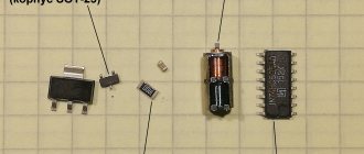
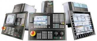
A single-phase motor operates using alternating electric current and is connected to single-phase networks. The network must have a voltage of 220 Volts and a frequency of 50 Hertz.
Electric motors of this type are used mainly in low-power devices:
- Household appliances.
- Low power fans
- Pumps.
- Machines for processing raw materials, etc.
Models are available with power from 5 W to 10 kW.
The values of efficiency, power and starting torque for single-phase motors are significantly lower than for three-phase devices of the same size. The overload capacity is also higher for 3-phase motors. Thus, the power of a single-phase mechanism does not exceed 70% of the power of a three-phase mechanism of the same size.
device
Device:
- In fact, it has 2 phases , but only one of them does the work, which is why the motor is called single-phase.
- Like all electric machines , a single-phase motor consists of 2 parts: stationary (stator) and moving (rotor).
- It is an asynchronous electric motor , the stationary component of which has one working winding, connected to a single-phase alternating current source.
The strengths of this type of engine include the simplicity of the design, which is a rotor with a squirrel-cage winding. The disadvantages are low starting torque and efficiency.
The main disadvantage of single-phase current is its inability to generate a magnetic field that performs rotation. Therefore, a single-phase electric motor will not start on its own when connected to the network.
In the theory of electrical machines, the rule applies: in order for a magnetic field to arise that rotates the rotor, there must be at least 2 windings (phases) on the stator. It is also required to shift one winding by a certain angle relative to the other.
During operation, alternating electric fields flow around the windings:
- In accordance with this , the so-called starting winding is located on the stationary section of the single-phase motor. It is shifted 90 degrees relative to the working winding.
- A current shift can be obtained by including a phase-shifting link in the circuit. Active resistors, inductors and capacitors can be used for this.
- 2212 electrical steel is used as the basis
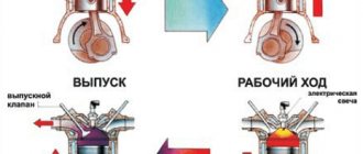
Operating principle and startup scheme
Principle of operation:
- An electric current generates a pulsating magnetic field on the motor stator. This field can be considered as 2 different fields that rotate in different directions and have equal amplitudes and frequencies.
- When the rotor is stationary , these fields lead to the appearance of moments of equal magnitude, but differently directed.
- If the engine does not have special starting mechanisms , then at start the resulting torque will be zero, which means the engine will not rotate.
- If the rotor is rotated in one direction , then the corresponding torque begins to prevail, which means that the motor shaft will continue to rotate in the given direction.
Launch scheme:
- The launch is carried out by a magnetic field , which rotates the moving part of the motor. It is created by 2 windings: main and additional. The latter is smaller in size and is a launcher. It is connected to the main electrical network through capacitance or inductance. The connection is made only during start-up. In low power motors, the starting phase is short-circuited.
- The engine is started by holding the start button for a few seconds, as a result of which the rotor accelerates.
- When the start button is released , the electric motor switches from two-phase mode to single-phase mode, and its operation is supported by the corresponding component of the alternating magnetic field.
- The starting phase is designed for short-term operation – usually up to 3 s. A longer time under load can lead to overheating, insulation fire and mechanism failure. Therefore, it is important to release the start button in a timely manner.
- In order to increase reliability, a centrifugal switch and a thermal relay are built into the housing of single-phase motors.
- The function of the centrifugal switch is to cut off the starting phase when the rotor reaches its rated speed. This happens automatically - without user intervention.
- The thermal relay turns off both phases of the winding if they heat up above the permissible level.
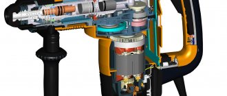
Design features
If we compare a single-phase electric motor with other electric machines, then structurally it also consists of a movable and stationary element - a stator and a rotor. The stator, due to the flow of electric current through its windings, creates a magnetic field that interacts with the rotor. As a result of electromagnetic interaction, the rotor is rotated.
Rice. 1. Design of single-phase asynchronous electric motor
However, everything is not as simple as it might seem at first glance; if you removed the extra two windings from a conventional three-phase electric motor and plugged it into an outlet, rotation would not start. The motor simply does not have enough torque to rotate the rotor. Therefore, the design of a single-phase asynchronous electric motor has a number of features.
Rotor
The rotor of a single-phase electric motor is the same metal shaft, which is equipped with a winding. A ferromagnetic frame made of laminated steel is assembled on the shaft and grooves are made along its outer surface. Rods made of copper or aluminum are installed in the grooves on the rotor shaft, which act as a winding that conducts electric current. At the ends, the rods are connected by two rings, due to this design it is also called a squirrel cage.
When an electromagnetic flux from the stator is applied to the short-circuited windings of the rotor, current begins to flow in the squirrel cage. A ferromagnetic insert on the shaft helps to enhance the flux passing through it. However, not all models have a magnetic conductor; in some it is made of non-magnetic alloys.
Stator
The stator design in a single-phase electric motor has the same composition as in most electrical machines:
- metal case;
- a magnetic circuit made of ferromagnetic material installed inside;
- stator winding, represented by copper conductors.
The stator windings of such an electric motor are divided into two - the main winding, which is also the working winding, through which the load is constantly circulated, and the starting winding, which is activated only at the time of start-up. Both windings of a single-phase motor are located at an angle of 90° relative to each other. This design makes them similar to two-phase electric motors, which also use two windings.
But their volume, relative to the entire space of the asynchronous motor, is different; the main one is only 2/3 of the total number of slots, and the starting windings occupy 1/3.
Connection
To operate the device, 1 phase with a voltage of 220 Volts is required. This means that you can plug it into a household outlet. This is precisely the reason for the popularity of the engine among the population. All household appliances, from a juicer to a grinder, have mechanisms of this type.
connection with starting and running capacitors
There are 2 types of electric motors: with a starting winding and with a working capacitor:
- In the first type of device , the starting winding operates via a capacitor only during start. Once the machine reaches normal speed, it turns off and operation continues with one winding.
- In the second case , for motors with a working capacitor, the additional winding is permanently connected through the capacitor.
An electric motor can be taken from one device and connected to another. For example, a working single-phase motor from a washing machine or vacuum cleaner can be used to operate a lawn mower, processing machine, etc.
There are 3 schemes for switching on a single-phase motor:
- In scheme 1 , the work of the starting winding is performed by means of a capacitor and only for the starting period.
- 2 circuit also provides for a short-term connection, but it occurs through a resistance and not through a capacitor.
- Scheme 3 is the most common. In this scheme, the capacitor is constantly connected to a source of electricity, and not just during startup.
Connecting an electric motor with starting resistance:
- The auxiliary winding of such devices has increased active resistance.
- To start an electrical machine of this type, a starting resistor can be used. It should be connected in series to the starting winding. Thus, it is possible to obtain a phase shift of 30° between the winding currents, which will be quite enough to start the mechanism.
- Alternatively , a phase shift can be obtained by using a starting phase with a higher resistance value and a lower inductance value. This winding has fewer turns and thinner wire.
Read also: What is circuit inductance
Connecting a motor with a capacitor start:
- For these electric machines, the starting circuit contains a capacitor and is turned on only for the start period.
- To achieve the maximum starting torque, a circular magnetic field is required that performs the rotation. For it to occur, the winding currents must be rotated 90° relative to each other. Phase-shifting elements such as a resistor and inductor do not provide the necessary phase shift. Only the inclusion of a capacitor in the circuit allows you to obtain a phase shift of 90°, if you select the capacitance correctly.
- calculate which wires belong to which winding by measuring the resistance. For the working winding, its value is always less (about 12 Ohms) than for the starting winding (usually about 30 Ohms). Accordingly, the cross-section of the working winding wire is larger than that of the starting winding.
- The capacitor is selected according to the current consumed by the motor. For example, if the current is 1.4 A, then a capacitor with a capacity of 6 μF is required.
How to connect
You can connect a single-phase electric motor to a power outlet using special connectors - a plug. It is necessary to have a voltage of 220 - 240 V and a current frequency of 50 Hz. Regardless of what kind of device it is - a juicer, mixer, electric meat grinder or vacuum cleaner, the connectors of the connected electrical appliance and sockets always match!
The electric motor can be started using a capacitor of the correct capacity, connected to the starting winding, or using a resistor.
Usually all this is already provided for in the design. Just “plug the plug into the socket” and press the “start” button.
At the same time, the trigger mechanism can operate either briefly or be permanently connected to the circuit.
Thus, when choosing a purposeful “motor” for a single-phase network, it is important to start it correctly. Household appliances already have the necessary settings, just press a button
In other cases, you need to choose the right starting device so that the engine starts and performs its assigned tasks.
Functionality check
How to check engine performance by visual inspection?
The following are defects that indicate possible problems with the engine; they could be caused by improper operation or overload:
- Broken support or mounting gaps.
- in the middle of the engine has darkened (indicates overheating).
- through cracks in the housing.
To check the performance of the engine, you should first turn it on for 1 minute, and then let it run for about 15 minutes.
If after this the engine is hot, then:
- Perhaps the bearings are dirty, jammed, or simply worn out.
- The reason may be that the capacitor capacitance is too high.
Disconnect the capacitor and start the motor manually: if it stops heating, you need to reduce the capacitor capacitance.
Model overview
One of the most popular are electric motors of the AIR series. There are models made on feet 1081, and models of combined design - feet + flange 2081.
Electric motors in the foot + flange design will cost about 5% more than similar ones with feet.
As a rule, manufacturers provide a warranty of 12 months.
For electric motors with a rotation height of 56-80 mm, the frame is made of aluminum. Motors with a rotation height of more than 90 mm are available in cast iron.
Models differ in power, rotation speed, height of the rotation axis, and efficiency.
The more powerful the engine, the higher its cost:
- An engine with a power of 0.18 kW can be purchased for 3 thousand rubles (electric motor AIRE 56 B2).
- A model with a power of 3 kW will cost about 10 thousand rubles (AIRE 90 LB2).
The height of the rotation axis for motors with 1 phase varies from 56 mm to 90 mm and directly depends on the power: the more powerful the engine, the greater the height of the rotation axis, and therefore the price.
Different models have different efficiencies, typically ranging from 67% to 75%. Greater efficiency corresponds to a higher cost of the model.
You should also pay attention to engines produced by the Italian company AACO, founded in 1982:
- Thus, the AACO series 53 electric motor is designed specifically for use in gas burners. These motors can also be used in washing installations, warm air generators, and central heating systems.
- Electric motors of the 60, 63, 71 series are designed for use in water supply installations. Also, the company offers universal motors of the 110 and 110 compact series, which are distinguished by a diverse range of applications: burners, fans, pumps, lifting devices and other equipment.
You can buy motors produced by AACO for a price starting from 4,600 rubles.
First, let's find out the type of engine. We will not always resolve the issue unambiguously. Appearance says little; the nameplate of an old engine may not correspond to the actual contents of the unit. We propose to briefly consider what asynchronous and commutator motors the industry produces. We will tell you the differences in operation, key properties, external and internal. Let's discuss connecting a single-phase motor to an AC mains.
Brushed vs asynchronous motors
The question - commutator motor or asynchronous - is resolved as a matter of priority. The process is simple. A collector is a drum divided by copper sections, approximately rectangular in shape, made of copper. Forms a current collector; in commutator motors, the rotor is always powered by electric current. Constant, variable - the field is created by the applied voltage.
The commutator motor contains at least two brushes. We rarely see three-phase ones. Information about such units is described in literature from the middle of the last century. Three-phase commutator motors were used, regulating the shaft rotation speed over a wide range. The motor of this type is equipped with brushes and a copper drum divided into sections. It is difficult to miss the sign even with the naked eye. Examples of commutator motors:
- Vacuum cleaner, washing machine.
- Grinder, drill, electric hand tool.
Commutator motors are widely used, providing a relatively simple reverse, realized by changing the commutation of the windings. The speed is regulated by changing the supply voltage cutoff angle or amplitude. Common disadvantages of commutator motors include:
- Noisy. Friction by drum brushes cannot occur silently. When crossing the section, sparking occurs. The effect causes radio frequency interference, producing a host of extraneous sounds. Commutator motors are relatively noisy. Try to remember the vacuum cleaner. Is the washing machine not so loud when performing the washing cycle? Low speed brushed motors are good.
- The need for maintenance is determined by the presence of rubbing parts. The current collector is often contaminated with graphite. It is simply unacceptable; it can short-circuit adjacent sections. Dirt increases noise levels and other negative effects.
Everything is good in moderation. Brushed motors will allow you to obtain a given power (torque) at the start, after acceleration. It is relatively easy to adjust the speed. The reason for the fascination of household appliances with commutator varieties has been named; asynchronous motors are the heart of equipment that has increased requirements for sound pressure levels. Fans, hoods. Serious loads will require major design changes. Cost, size, and complexity increase, making production unprofitable.
A commutator engine is distinguished by the presence of... a commutator. Even if you cannot see it from the outside (hidden by the casing), we will notice the indispensable graphite brushes, pressed by springs. The part requires replacement over time; it will help to distinguish a commutator motor from an asynchronous one.
Single-phase and three-phase asynchronous motors
We agreed - three-phase commutator motors are difficult to obtain; the current section concerns asynchronous machines. We list the varieties:
- Three-phase asynchronous motors are equipped with a number of outputs from three to six working windings minus various fuses, internal relays, and various sensors. The stator coils inside are connected by a star, making it impossible to directly connect to a single-phase network.
- Single-phase motors equipped with a starting winding are, among other things, equipped with a pair of contacts leading to a centrifugal limit switch. The miniature device breaks the chain when the shaft is untwisted. The starting winding catalyzes the initial stage. Further action will interfere, reducing the efficiency of the engine. The design is usually called bifilar. The starting winding is wound with double wire, reducing reactance. Helps reduce the capacitance of the capacitor - critical. A striking example of single-phase asynchronous motors with a starting winding are the compressors of household refrigerators.
- The capacitor winding, different from the starting winding, operates continuously. We will find the motors inside the floor fans. The capacitor provides a phase shift of 90 degrees, allowing you to choose the direction of rotation and maintain the desired shape of the electromagnetic field inside the rotor. Typically the capacitor is mounted on the motor housing.
Read also: Diagnostics of the generator voltage regulator
Three-phase asynchronous motors
Let's learn how to distinguish single-phase asynchronous motors from three-phase ones. In the latter case, there are always three equal windings inside. Therefore, you can find three pairs of contacts that, when examined by a tester, give the same resistance. For example, 9 ohms. If the windings are connected by a star inside, there will be three terminals with the same resistance. Of these, any pair gives identical readings displayed on the multimeter screen. The resistance is equal to two windings each time.
Because current must flow out, sometimes a three-phase motor has a neutral terminal. The center of the star, with each of the other three wires, gives identical resistance, half that shown by the pairwise continuity. The above symptoms speak eloquently: the motor is three-phase, alien to the topic of today’s conversation.
The winding motors discussed in this section contain two. One starting or capacitor (auxiliary). There are usually three or four conclusions. If there is no capacitor decorating the case, you can try to reason, puzzled by the purpose of the contacts, as follows:
- There are four pins - you need to measure the resistance. Usually they ring in pairs. The resistance is lower - we found the main winding connected to a 230 volt network without a capacitor. Polarity does not matter; the direction of rotation is set by the way the auxiliary winding is turned on, by switching the coils. Simply put, connect a single-phase electric motor of a characteristic type with only one main winding - in the initial period of time the shaft stands upright. Wherever you spin, there will be rotation. Beware of starting with your hand - it will break.
Asynchronous motor device
Distinguishing types of single-phase motors in practice
Let's learn how to distinguish a bifilar motor from a capacitor motor. It should be said that the difference is purely nominal. The connection diagram for a single-phase motor is similar. The bifilar winding is not designed to operate continuously. It will interfere and reduce efficiency. Therefore, it is interrupted after a set of revolutions by a start-up relay (inherent in household refrigerators) or by centrifugal switches. It is believed that the starting winding operates for several seconds. According to generally accepted standards, it will launch 30 times per hour, lasting 3 seconds each. Then the coils may overheat (burn out). The reason that limits the starting winding being energized.
The difference is nominal, but professionals note an interesting feature by which they judge whether we have a bifilar or capacitor motor. Auxiliary winding resistance. The nominal value differs from the working one by more than 2 times, most likely the engine is bifilar. Accordingly, the winding is starting. A capacitor motor operates using the services of two coils. Both are constantly under tension.
Single phase asynchronous motor
The test must be carried out carefully; in the absence of thermal fuses and other means of protection, the starting winding may burn out. You will have to unscrew the shaft manually, which is clearly not an easy task. Sometimes it is advisable to connect a single-phase asynchronous motor to a single-phase network using a similar circuit, as was done in previous equipment. An ordinary refrigerator is equipped with a start-up relay, a separate topic of discussion. The parameters of the device are closely related to the type of engine used; mutual replacement is not possible in every case (violation of a simple rule can cause breakdown).
Let us mention it twice: there can be three or four winding terminals. The number is not informative. A pair of thermal fuse contacts is acceptable. Plus the above, including the centrifugal switch. In the case of continuity, the resistance is either low, or vice versa - we fix the gap. By the way, do not forget to test each end of the coil against the body when determining the resistance. Insulation is standard not lower than 20 MOhm. Otherwise, you should think about the presence of a breakdown. We also assume that a three-phase motor with internal star-type winding commutation may have a neutral output to the housing. In this case, the motor requires an indispensable grounding, for which a terminal is provided (but it is more likely that the motor simply failed due to an insulation breakdown).
Types of electrical machine repairs
To prevent malfunctions, maintenance and scheduled repairs of electrical equipment should be carried out according to the approved schedule.
Electrical machine repairs are divided into maintenance (MOT), current, medium and major repairs. The scope of work in each of these types of work is determined by the “Standard Regulations on Maintenance and Repair (MRO) of Electrical Equipment”.
Maintenance
This is to maintain equipment in working order between scheduled repairs. Carried out by maintenance and operational maintenance personnel.
Provides for the following types of work:
- inspection;
- heating check;
- wiping off dirt;
- insulation check;
- identifying faults and eliminating them.
It is carried out according to the approved schedule and during downtime - lunch break, adjustment, tool change.
Maintenance
Maintained in working condition until repaired. Produced on site or in a workshop. Includes:
- complex of maintenance works;
- replacement of failed components - bearings and couplings;
- adjustment and checking of alignment.
Medium renovation
For problems that cannot be eliminated during routine repairs, a medium repair is performed. This produces:
- complete disassembly;
- if necessary, replace bearings;
- repair of housing and shaft;
- impregnation of windings with varnish;
- insulation or replacement of leads
Medium repairs are carried out in specialized workshops and enterprises.
Major renovation
Complete restoration of characteristics and parameters. In addition to the complex of medium repair works, the windings of the electric machine are replaced or repaired.
Electric motor malfunctions are easier to prevent than to eliminate their consequences. To do this, it is necessary to carry out a set of work on servicing the mechanism in a timely manner and equip it with the necessary protective devices.
{SOURCE}
Tags: automatic, sconce, type, choice, switch, engine, house, , capacity, replacement, insulation, like, kW, capacitor, design, , magnet, power, voltage, nominal, connection, rule, check, wire, manufacturer, start, , work, size, calculation, resistor, resonance, relay, repair, row, connection, term, circuit, type, current, , shield, effect
How to choose a capacitor for starting a single-phase motor
We have already told you how to select a capacitor for starting a three-phase motor, but the method is not suitable in our case. Amateurs recommend trying to enter the so-called resonance. In this case, the consumption of a 9 kW unit will be about (!) 100 W. This does not mean that the shaft will pull the full load, but in idle mode the consumption will be minimal. How to connect an electric motor this way.
Amateurs recommend focusing on current consumption. At the optimal capacity value, the power will be minimal. You can estimate the current consumption using a Chinese multimeter. And so, the connection of a single-phase motor with a starting winding is carried out, guided by the electrical diagram indicated on the housing. For example, there is information there:
- The color of the cambric of a certain winding.
- Electrical switching diagram for an alternating current circuit.
- Nominal capacity used.
Read also: Flux for aluminum casting
So, if you take a single-phase asynchronous motor, the connection diagram is often indicated on the housing.
The question of how to connect a single-phase electric motor very often arises in practice due to the high popularity of using such units for solving various household problems.
The connection diagram for a single-phase electric motor is quite simple and requires taking into account only one fundamental point: to ensure its operation, a rotating magnetic field is necessary. If there is only a single-phase alternating current network at the time of starting the electric motor, it must be formed artificially through the use of appropriate circuit solutions.
- Electric motor windings
- Features of torque formation
- Capacitors
- Indirect inclusion
- Features of using a magnetic starter
- Conclusion
Features of connecting a single-phase 220 V electric motor.
A starting resistance is used to drive an asynchronous single-phase electric motor. This method is used in split-phase devices. The electrical circuit of the motor contains a rotor and a stator. The winding of the second is shifted relative to the main one. In this case, the working element has less resistance than the auxiliary element. The ohmic phase shift is ensured by bifilar winding. Connection without a resistor is impossible.
A special feature of a single-phase motor is the connection of the auxiliary winding to a capacitor. Work begins only after the starting moment occurs. A capacitor is required to obtain the maximum value. Thanks to it, a starting moment arises, which puts all the mechanisms into operation.
Electric motor windings
Laying windings in the stator of a single-phase electric motor
The design of any single-phase electric motor requires the use of at least three coils. Two of them are stator structural elements connected in parallel. One of them is working, and the second serves as a launcher. Their terminals are located on the motor housing and are used to connect to the network. The rotor winding is short-circuited. Two of them will be connected to the network, the rest are used for switching.
To change the power, the working coil can be formed from two parts, which are connected in series.
You can visually identify the working and starting windings by the cross-section of the wire: for the first of them it is noticeably larger. You can measure the resistance with a tester by connecting it to the terminals: at the working winding its value will be less. As a rule, the resistance of the windings will be no more than several tens of ohms.
Three-phase
The AC induction motor has a very simple design compared to other types of electrical machines. It is quite reliable, which explains its popularity. Three-phase models are connected to an alternating voltage network with a star or delta. Such electric motors also differ in operating voltage: 220–380 V, 380–660 V, 127–220 V.
As a rule, such electric motors are used in production, since three-phase voltage is most often used there. And in some cases it happens that instead of 380 V there is three-phase 220. How to connect them to the network so as not to burn the windings?
Features of torque formation
The magnetic field created by the motor coils has a phase shift of 90 degrees. This is usually achieved through a capacitor that is connected in series with the trigger circuit. Possible connection options are shown in the figure below.
Options for creating a phase shift
The trigger coil can operate continuously. A scheme based on its shutdown after reaching the rated rotor speed is also acceptable. The permanent connection of the starting winding complicates the design of the motor, but improves its performance. These differences do not affect the characteristics of connecting to the network.
To simplify starting an engine with a working capacitor, before applying current to it from the network, an auxiliary capacitance is connected in parallel to it.
A single-phase electric motor allows you to simply change the direction of shaft rotation to the opposite direction. To do this, the phase of the current coming from the network and flowing through the starting circuit is shifted to the opposite one. This procedure is implemented by simply changing the order in which the starting winding is turned on when it is connected to the working winding.
Capacitors
Connection diagram for single-phase capacitor motors: a – with working capacitance Cp, b – with working capacitance Cp and starting capacitance Sp.
The electric motor can be equipped with two types of capacitors. The presence of a capacitance connected in series with the trigger winding and passing current through it to shift the phase is mandatory. Its value is borrowed from the motor’s passport data and is duplicated on its nameplate.
If a capacitor of the required capacity is not available, it is permissible to use any other with a similar rating. If the deflection is too much downward, the engine may not start to rotate without manually cranking the shaft, and then will not develop the required power. If the capacity is significantly exceeded, intense heating will begin.
The capacity of the additional starting component is selected two to three times higher than the main one. This value provides maximum starting torque.
To turn on the trigger element, either a regular button or more complex circuits can be used.
General diagrams for connecting motors from 380V to 220V via a capacitor
Most often, when it is necessary to solve such a problem, working and starting capacitors (capacitor banks) are used. Basic 380V delta and star connection diagrams can be seen in the following illustration:
The non-fixed "Acceleration" button is used to activate a parallel-connected starting capacitor. It must be held until the engine reaches maximum speed. After this, the starting circuit must be disconnected to prevent overheating of the windings. If the engine power is low, the starting capacitor can be neglected, working only through the working capacitor.
Capacitor capacitance is calculated using the following formulas:
The capacity of the starting capacitor should be twice as high as the working one. If you do not resort to calculations using formulas, you can use the value 7 µF/kW.
Practical application shows that a triangle connection is more effective, since in this case the voltage distribution in the windings will be more uniform, and the power will be reduced less. There is however one limitation, which concerns the layout of the motor terminal block. If under its cover there are only three 380 pins, then there is a preset connection diagram that cannot be changed. If there are six pins there, then you can choose which option to organize. The characteristic designation is applied to a metal plate with characteristics.
If a 380-volt motor is supposed to be used at 220V in a mode with frequent starts and stops, then the basic circuit can be modified to organize a dynamic braking circuit:
Here you can see the motor being turned on by a triangle through a capacitive circuit of capacitors C1 (starting) and C2 (working). Additionally, a circuit is organized on a transistor and a resistance element, which is connected with a three-position switch. When it is in position “3”, the 220V mains voltage is supplied to the stator windings and with the K1 button you can start it. To stop the engine, the key is turned to position “1”, after which direct current is supplied to the windings and braking is performed. It should be noted that this switch has only two fixed positions “2” and “3”. To use a conventional two-position switch, you will need to add another capacitor to this circuit. It looks like this:
We have already mentioned the fact that single-phase current leads to the organization of multidirectional equivalent magnetic fields of the stator and rotor, which can be shifted (forced to rotate) in one direction or another. Therefore, it is possible to implement in practice a reverse connection scheme for a 380V electric motor:
The circuit is in some way a combination of the previous two, only here a double switch and a start through relay P1 are used.
https://youtube.com/watch?v=tqwz6Uv7mlE
The circuits discussed in the article are basic, but depending on the specific case, they can be modified in any way to achieve inclusion of a 380V three-phase asynchronous electric motor in a single-phase 220V network.
Indirect inclusion
Connecting a single-phase motor
The main component of the indirect connection circuit is a magnetic starter, which is connected to the gap between the power network output and the electric motor.
The power contacts of this block are designed as normally open. Based on the maximum current flowing through it, a magnetic starter belongs to one of seven standardized groups. Due to the low power of single-phase electric motors, a device of the first group is usually sufficient, the maximum switching current of which is 10 A.
The control part of the coil is designed for connection to networks with different voltages. The most convenient is a magnetic starter controlled from 220V AC.
Switching to the desired voltage
First we need to make sure that our engine has the necessary parameters. They are written on a tag attached to his side. It should indicate that one of the parameters is 220V. Next, let's look at the connection of the windings. It is worth remembering this pattern of the circuit: star - for lower voltage, triangle - for higher voltage. What does this mean?
Voltage increase
Let's say the tag says: Δ/Ỵ220/380. This means that we need a delta connection, since most often the default connection is 380 volts. How to do it? If the electric motor in the burner has a terminal box, then it is not difficult. There are jumpers there, and all you need to do is switch them to the desired position.
In this situation this does not cause any difficulties. The main thing to remember is that there is a beginning and an end to the coils. For example, let’s take as a starting point the ends that were brought out into the boron of the electric motor. This means that what is soldered is the ends
Now it’s important not to confuse
We connect like this: we connect the beginning of one coil to the end of the other, and so on.
As you can see, the scheme is simple. Now the engine, which was connected for 380, can be connected to a 220 volt network.
Voltage reduction
Let's say the tag says: Δ/Ỵ 127/220. This means a star connection is required. Again, if there is a terminal box, then everything is fine
What if not, and our electric motor is turned on in a triangle? And if the ends are not signed, then how to connect them correctly? After all, here it is also important to know where the coil winding begins and where the end is. There are some ways to solve this problem
First, let's move all six ends apart and use an ohmmeter to find the stator coils themselves.
We take a regular battery and connect it to ends a1-a2. We connect an ohmmeter to the other two ends (c1-c2).
At the moment the contact with the battery is broken, the arrow of the device will swing to one side. Let's remember where it swung and turn on the device to ends c1-c2, without changing the polarity of the battery. Let's do it all over again.
If the arrow deviates in the other direction, then we swap the wires: we mark c1 as c2, and c2 as c1. The point is that the deviation is the same.
Now we connect the battery, observing polarity, to ends c1-c2, and the ohmmeter to a1-a2.
We ensure that the needle deflection on any reel is the same. Let's double check again. Now one bundle of wires (for example, with the number 1) will be the beginning, and the other will be the end.
We take three ends, for example, a2, b2, c2, and connect them together and isolate them. This will be a star connection. As an option, we can output them directly to the terminal block and label them. We paste the connection diagram onto the lid (or draw it with a marker).
Switching triangle - star done. You can connect to the network and work.
Features of using a magnetic starter
The control part of the device has several pairs of contacts on which the relay automation circuit is assembled. One of them is always normally closed, and the second is always normally open.
The “Start” button has a normally open contact, while the “Stop” button has a normally closed element.
When connecting the device in question, several types of connections are made.
Single-phase motor connection diagram
The phase, along with the input terminal, is also connected to the contact input of the “Stop” button, and the zero is connected to the input terminal of the coil, which ensures that control current flows through it.
The active contact of the “Start” button when the engine is running is bypassed by a similar element of the coil. To form this circuit, two additional connections are made, the diagram of which is shown in the figure above:
- the output of the working contact of the “Stop” button is connected in parallel with the output contacts of the “Start” button and the input of the control coil;
- the output of the normally open contact of the control coil is connected in parallel to its output terminal and to the input of the working contact of the “Start” button.