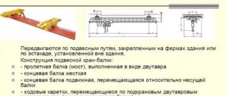
Wooden beams
Today's individual construction involves the widespread use of beams made of wood. Almost every building contains wooden floors. Wooden beams can be used as load-bearing elements; they are used in the manufacture of floors, and also as supports for floors between floors.
It's no secret that a wooden beam, like a steel beam, tends to bend under the influence of load forces. The deflection arrow depends on what material is used, the geometric characteristics of the structure in which the beam is used, and the nature of the loads.
The permissible deflection of the beam is formed from two factors:
- Correspondence between deflection and permissible values.
- Ability to operate the building taking into account deflection.
Strength and rigidity calculations carried out during construction make it possible to most effectively assess what loads the building can withstand during operation. Also, these calculations make it possible to find out exactly what the deformation of structural elements will be in each specific case. Perhaps no one will argue that detailed and most accurate calculations are part of the responsibilities of civil engineers, but with the use of several formulas and the skill of mathematical calculations, you can calculate all the necessary quantities yourself.
In order to correctly calculate the deflection of a beam, you must also take into account the fact that in construction the concepts of rigidity and strength are inseparable. Based on the strength calculation data, you can proceed to further calculations regarding rigidity. It is worth noting that calculating the deflection of a beam is one of the indispensable elements of calculating rigidity.
Please note that to carry out such calculations yourself, it is best to use large-scale calculations, while resorting to fairly simple schemes. It is also recommended to make a small margin in the larger direction. Especially if the calculation concerns load-bearing elements.
Maximum deflection of a metal beam - Metalworker's Handbook
The beam is the main element of the supporting structure of the structure.
During construction, it is important to calculate the deflection of the beam. In real construction, this element is affected by wind force, loading and vibration. However, when performing calculations, it is customary to take into account only the transverse load or the applied load, which is equivalent to the transverse one. When calculating, the beam is perceived as a rigidly fixed rod, which is installed on two supports. If it is installed on three or more supports, calculating its deflection is more complex, and it is almost impossible to do it yourself.
The main load is calculated as the sum of forces that act in the direction of the perpendicular section of the structure. A design diagram is required to determine the maximum deformation, which should not exceed the limit values.
This will allow you to determine the optimal material of the required size, cross-section, flexibility and other indicators.
Types of beams
Beams made of strong and durable materials are used for the construction of various structures. Such structures may differ in length, shape and cross-section.
Wooden and metal structures are most often used. For the deflection calculation scheme, the material of the element is of great importance.
The specifics of calculating the deflection of a beam in this case will depend on the homogeneity and structure of its material.
Wooden
For the construction of private houses, cottages and other individual construction, wooden beams are most often used. Wooden structures that work in bending can be used for ceilings and floors.
To calculate the maximum deflection, consider:
- Material. Different types of wood have different strength, hardness and flexibility.
- Cross-sectional shape and other geometric characteristics.
- Various types of load on the material.
The permissible deflection of the beam takes into account the maximum real deflection, as well as possible additional operational loads.
Coniferous wood structures
Steel
Metal beams have a complex or even composite cross-section and are most often made from several types of metal. When calculating such structures, it is necessary to take into account not only their rigidity, but also the strength of the connections.
Metal structures are made by connecting several types of rolled metal, using the following types of connections:
- electric welding;
- rivets;
- bolts, screws and other types of threaded connections.
Steel beams are most often used for multi-story buildings and other types of construction where high structural strength is required. In this case, when using high-quality connections, a uniformly distributed load on the beam is guaranteed.
To calculate the beam for deflection, this video can help:
Beam strength and rigidity
To ensure the strength, durability and safety of the structure, it is necessary to calculate the deflection value of the beams at the design stage of the structure. Therefore, it is extremely important to know the maximum deflection of the beam, the formula of which will help draw a conclusion about the likelihood of using a certain building structure.
Using a calculation scheme of rigidity allows you to determine the maximum changes in the geometry of the part. Calculating a structure using experimental formulas is not always effective.
It is recommended to use additional coefficients to add the necessary safety margin.
Not leaving an additional margin of safety is one of the main construction mistakes, which leads to the impossibility of using the building or even serious consequences.
There are two main methods for calculating strength and stiffness:
- Simple. When using this method, a magnification factor is applied.
- Accurate. This method includes the use of not only safety factors, but also additional calculations of the boundary state.
The last method is the most accurate and reliable, because it helps determine exactly what load the beam can withstand.
Stiffness calculation
To calculate the bending strength of a beam, the formula is used:
Where:
M is the maximum moment that occurs in the beam;
Wn,min – moment of resistance of the section, which is a tabular value or is determined separately for each type of profile.
Ry is the design bending resistance of the steel. Depends on the type of steel.
γc is the operating condition coefficient, which is a tabular value.
Calculating the stiffness or deflection of a beam is quite simple, so even an inexperienced builder can perform the calculations. However, to accurately determine the maximum deflection, you must perform the following steps:
- Drawing up a design diagram of the object.
- Calculation of the dimensions of the beam and its section.
- Calculation of the maximum load that acts on the beam.
- Determination of the point of application of maximum load.
- Additionally, the beam can be tested for strength by maximum bending moment.
- Calculation of the stiffness value or maximum deflection of a beam.
To create a calculation scheme, you will need the following data:
- beam dimensions, length of consoles and span between them;
- cross-sectional size and shape;
- features of the load on the structure and its exact application;
- material and its properties.
If a two-support beam is being calculated, then one support is considered rigid, and the second is considered hinged.
Calculation of moments of inertia and section resistance
To perform stiffness calculations, you will need the moment of inertia of the section (J) and the moment of resistance (W). To calculate the moment of resistance of a section, it is best to use the formula:
An important characteristic when determining the moment of inertia and resistance of a section is the orientation of the section in the cut plane. As the moment of inertia increases, the stiffness index also increases.
Determination of maximum load and deflection
To accurately determine the deflection of a beam, it is best to use this formula:
Where:
q is a uniformly distributed load;
E – elastic modulus, which is a tabular value;
l – length;
I – moment of inertia of the section.
To calculate the maximum load, static and periodic loads must be taken into account. For example, if we are talking about a two-story structure, then the wooden beam will be constantly subject to the load from its weight, equipment, and people.
Features of deflection calculations
Deflection calculations are required for any floors. It is extremely important to accurately calculate this indicator under significant external loads. In this case, it is not necessary to use complex formulas. If you use the appropriate coefficients, the calculations can be reduced to simple schemes:
- A rod that rests on one rigid and one hinged support and carries a concentrated load.
- A rod that rests on a rigid and hinged support and is subject to a distributed load.
- Options for loading a cantilever rod that is rigidly fixed.
- The effect of a complex load on a structure.
Using this method for calculating deflection allows you to ignore the material. Therefore, the calculations are not affected by the values of its main characteristics.
Example of calculating deflection
To understand the process of calculating the stiffness of a beam and its maximum deflection, you can use a simple calculation example. This calculation is carried out for a beam with the following characteristics:
- material of manufacture – wood;
- density is 600 kg/m3;
- length is 4 m;
- the cross-section of the material is 150*200 mm;
- the mass of the covering elements is 60 kg/m²;
- the maximum load of the structure is 249 kg/m;
- the elasticity of the material is 100,000 kgf/m²;
- J is equal to 10 kg*m².
To calculate the maximum permissible load, the weight of the beam, floors and supports is taken into account. It is also recommended to take into account the weight of furniture, appliances, decoration, people and other heavy things, which will also have an impact on the structure. For the calculation you will need the following data:
- weight of one meter of beam;
- weight m2 of floor;
- the distance that is left between the beams;
- temporary load;
- load from partitions on the floor.
To simplify the calculation of this example, you can take the mass of the floor as 60 kg/m², the load on each floor as 250 kg/m², the load on the partitions as 75 kg/m², and the weight of a meter of beam as 18 kg. With a distance between beams of 60 cm, the coefficient k will be equal to 0.6.
If you plug all these values into the formula, you get:
q = (60 + 250 + 75) * 0.6 + 18 = 249 kg/m.
To calculate the bending moment, use the formula f = (5 / 384) * [(qn * L4) / (E * J)] £ [¦].
Substituting the data into it, we get f = (5 / 384) * [(qn * L4) / (E * J)] = (5 / 384) * [(249 * 44) / (100,000 * 10)] = 0 .13020833 * [(249 * 256) / (100,000 * 10)] = 0.13020833 * (6,3744 / 10,000,000) = 0.13020833 * 0.0000063744 = 0.00083 m = 0.83 cm.
This is precisely the indicator of deflection when a maximum load is applied to the beam. These calculations show that when a maximum load is applied to it, it will bend by 0.83 cm. If this indicator is less than 1, then its use at the specified loads is allowed.
The use of such calculations is a universal way to calculate the rigidity of a structure and the amount of their deflection. It is quite easy to calculate these values yourself. It is enough to know the necessary formulas and also calculate the values. Some data needs to be taken in a table.
Calculation of beams for deflection. Work algorithm
In fact, the algorithm by which such a calculation is made is quite simple. As an example, we will consider a somewhat simplified calculation scheme, while omitting some specific terms and formulas. In order to calculate beams for deflection, it is necessary to perform a number of actions in a certain order. The calculation algorithm is as follows:
- A calculation scheme is drawn up.
- The geometric characteristics of the beam are determined.
- The maximum load on this element is calculated.
- If necessary, the strength of the beam is checked by bending moment.
- The maximum deflection is calculated.
As you can see, all the steps are quite simple and quite doable.
Drawing up a design diagram of a beam
In order to draw up a calculation scheme, you do not need much knowledge. To do this, it is enough to know the size and shape of the cross-section of the element, the span between the supports and the method of support. The span is the distance between two supports. For example, you use beams as supporting floor beams for the load-bearing walls of a house, between which there are 4 m, then the span will be equal to 4 m.
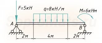
When calculating the deflection of a wooden beam, they are considered to be simply supported structural elements. In the case of a floor beam, a diagram with a load that is evenly distributed is adopted for the calculation. It is denoted by the symbol q. If the load is concentrated in nature, then a diagram with a concentrated load, denoted F, is taken. The magnitude of this load is equal to the weight that will exert pressure on the structure.
HORIZONTAL LIMIT DEFLECTIONS OF COLUMNS AND BRAKE STRUCTURES FROM CRANE LOADS
10.11. Horizontal maximum deflections of columns of buildings equipped with overhead cranes, crane trestles, as well as beams of crane tracks and brake structures (beams or trusses) should be taken according to Table. 21, but not less than 6 mm.
Deflections should be checked at the mark of the head of the crane rails from the braking forces of the trolley of one crane, directed across the crane runway, without taking into account the roll of the foundations.
Table 21
| Groups of crane operating modes | Limit deflections fu | ||
| columns | beams of crane tracks and brake structures, buildings and crane trestles (indoor and outdoor) | ||
| buildings and covered crane racks | open crane racks | ||
| 1K - 3K | h/500 | h/1500 | l/500 |
| 4K - 6K | h/1000 | h/2000 | l/1000 |
| 7K - 8K | h/2000 | h/2500 | l/2000 |
_____________
Designations adopted in table. 21:
h is the height from the top of the foundation to the head of the crane rail (for single-story buildings and indoor and outdoor crane trestles) or the distance from the axis of the floor beam to the head of the crane rail (for the upper floors of multi-story buildings);
l is the design span of the structural element (beam).
10.12. The horizontal maximum proximity of crane tracks of open trestles from horizontal and eccentrically applied vertical loads from one crane (without taking into account the roll of foundations), limited based on technological requirements, should be taken equal to 20 mm.
Moment of inertia
The geometric characteristic, which is called the moment of inertia, is important when calculating the deflection of a beam. The formula allows you to calculate this value; we will give it a little below.
When calculating the moment of inertia, you need to pay attention to the fact that the size of this characteristic depends on the orientation of the element in space. In this case, an inversely proportional relationship is observed between the moment of inertia and the amount of deflection. The smaller the moment of inertia value, the greater the deflection value and vice versa. This dependence is quite easy to track in practice. Every person knows that a board laid on its edge bends much less than a similar board in a normal position.
The moment of inertia for a beam with a rectangular cross-section is calculated using the formula:
J=b*h^3/12, where:
b – section width;
h is the height of the beam section.
Maximum load level calculations
The determination of the maximum load on a structural element is made taking into account a number of factors and indicators. Usually, when calculating the load level, they take into account the weight of 1 linear meter of beam, the weight of 1 square meter of floor, the temporary load on the floor and the load from partitions per 1 square meter of floor. The distance between the beams, measured in meters, is also taken into account. For an example of calculating the maximum load on a wooden beam, we will take the average values, according to which the weight of the floor is 60 kg/m², the temporary load on the floor is 250 kg/m², the partitions will weigh 75 kg/m². The weight of the beam itself is very easy to calculate, knowing its volume and density. Let's assume that a wooden beam with a cross-section of 0.15x0.2 m is used. In this case, its weight will be 18 kg/linear meter. Also, for example, let’s take the distance between the floor beams to be 600 mm. In this case, the coefficient we need will be 0.6.
As a result of calculating the maximum load, we obtain the following result: q=(60+250+75)*0.6+18=249 kg/m.
When the value is obtained, you can proceed to calculating the maximum deflection.
GENERAL INSTRUCTIONS
10.1. When calculating building structures based on deflections (bends) and displacements, the condition must be met:
(25)
where f is the deflection (bending) and displacement of a structural element (or the structure as a whole), determined taking into account the factors influencing their values, in accordance with paragraphs. 1-3 recommended applications 6;
fu is the maximum deflection (bending) and displacement established by these standards.
The calculation must be made based on the following requirements:
a) technological (ensuring conditions for normal operation of technological and handling equipment, instrumentation, etc.);
b) structural (ensuring the integrity of adjacent structural elements and their joints, ensuring specified slopes);
c) physiological (prevention of harmful effects and sensations of discomfort during vibrations);
d) aesthetic and psychological (providing favorable impressions from the appearance of structures, preventing the feeling of danger).
Each of these requirements must be met in the calculation independently of the others.
Limitations on structural vibrations should be established in accordance with the regulatory documents of paragraph 4 of recommended Appendix 6.
10.2. Design situations for which deflections and displacements, the corresponding loads, as well as requirements regarding construction lifting should be determined, are given in paragraph 5 of the recommended.
10.3. The maximum deflections of structural elements of coatings and ceilings, limited based on technological, structural and physiological requirements, should be counted from the curved axis corresponding to the state of the element at the time of application of the load from which the deflection is calculated, and those limited based on aesthetic and psychological requirements - from the straight line connecting supports for these elements (see also paragraph 7 of recommended Appendix 6).
10.4. Deflections of structural elements are not limited based on aesthetic and psychological requirements, if they do not worsen the appearance of the structures (for example, membrane coverings, inclined canopies, structures with a sagging or raised lower chord) or if the structural elements are hidden from view. Deflections are not limited based on the specified requirements for structures of floors and coverings above rooms with short-term occupancy of people (for example, transformer substations, attics).
Note. For all types of coatings, the integrity of the roofing carpet should, as a rule, be ensured by constructive measures (for example, the use of expansion joints, the creation of continuous coverage elements), and not by increasing the rigidity of the load-bearing elements.
10.5. The load reliability coefficient for all loads taken into account and the dynamic coefficient for loads from forklifts, electric vehicles, overhead and overhead cranes should be taken equal to unity.
Reliability coefficients for liability must be taken in accordance with mandatory Appendix 7.
10.6. For structural elements of buildings and structures, the maximum deflections and movements of which are not specified by this and other regulatory documents, vertical and horizontal deflections and movements from constant, long-term and short-term loads should not exceed 1/150 of the span or 1/75 of the cantilever overhang.
Calculation of the maximum deflection value
When a beam is calculated, the formula displays all the necessary elements. It should be borne in mind that the formula used for calculations may have a slightly different form if the calculation is carried out for different types of loads that will affect the beam.
First, we present to your attention the formula used to calculate the maximum deflection of a wooden beam with a distributed load.
f=-5*q*l^4/384*E*J.
Please note that in this formula E is a constant value, which is called the elastic modulus of the material. For wood, this value is 100,000 kgf/m².
Continuing the calculations with our data used for the example, we find that for a wooden beam with a cross-section of 0.15x0.2 m and a length of 4 m, the maximum deflection under the influence of a distributed load is 0.83 cm.
Please note that when the deflection is calculated taking into account a scheme with a concentrated load, the formula takes the following form:
f=-F*l^3/48*E*J, where:
F – pressure force on the beam.
We also draw attention to the fact that the value of the elastic modulus used in the calculations may vary for different types of wood. Not only the type of wood has an impact, but also the type of timber. Therefore, a solid wooden beam, laminated veneer lumber or rounded log will have different elastic moduli, and therefore different maximum deflection values.
You can pursue different goals when calculating beams for deflection. If you want to know the limits of deformation of structural elements, then after completing the calculation of the deflection arrow, you can stop. If your goal is to establish the level of compliance of the found indicators with building codes, then they need to be compared with the data that is posted in special regulatory documents.
Checking steel beam deflections
Tags: #LIRA-SAPR #STK #deflections
When calculating steel beams according to the IInd GPS (by deflections), it is necessary to create bracing for deflections:
Information from the LIRA SAPR Help (Help\Explanations Steel\Deflection Checks):
The deflection is checked by comparing the actually determined relative deflection (L/f) with the maximum possible deflection for a given structural element.
In this version, the check is performed only for beams based on the composition of load cases in all combinations. Load reliability coefficients (specified during the formation of the DCS in the LIRA-SAPR PC environment) and combination coefficients are taken into account.
Displacements caused by load cases with duration fraction 0 are not used in this calculation.
Deflections are found for each section based on the distribution of MY1, MZ1, QY1, QZ1 along the length of the element. Accordingly, an increase in the number of design sections contributes to a more accurate determination of deflections (especially if concentrated force factors act).
In the local element calculation mode (see the STK-SAPR help system), it is possible to calculate deflections using the bending moment envelope diagrams in reserve. This may be required when design combinations of forces (or loads) are edited and the connection with the results of the calculation on the LIRA-SAPR PC of the main scheme is lost.
Important: It is possible to determine not pure displacements (relative to the local Y and Z axes in an undeformed scheme), but deflection relative to two selected conditionally fixed points - anchorage points (in the case of a console, for example, relative to one point).
Scheme for determining beam deflections with and without bracing
The fragment shown shows the mechanism for determining deflections (they are designated as di and dk) in a structural element with braces applied to the elements.
If bracing is not applied, then the deflection is assumed to be equal to the full distance to the X axis.
Important: If a beam (crossbar) is split along its length by intermediate nodes, then it is necessary to create a structural element for it and create bracing to check deflections as for a structural element (i.e. for the beam as a whole). In the analysis of steel structures, the effective length factor (for both beams, columns, and trusses) is applied to the length of the finite element (FE), unless a structural element (SEC) is specified. If a CoE is specified, the effective length factor is applied to the total length of the CoE.
Example of calculation of a single-span beam
Calculation model of a frame with a solid crossbar and broken into separate elements
According to regulatory documentation, deflection is determined by the action of standard loads. Since in LIRA SAPR all loads are applied to nodes and elements with their design values, when determining deflections, the program determines the standard value of the loads by dividing them by the reliability factor.
You can see what reliability coefficients are accepted, and also enter them manually, if necessary, in the calculation parameters window.
Calculation parameters window called from the window for setting parameters for steel structures
For more information about adjusting safety coefficients for manually calculating deflections, read the article “Coefficients for live loads when checking deflections”
Mosaic of the results of checking the assigned sections for the 2nd limit state
Maximum permissible L/200=6000/200=30mm
Without specifying bracing (based on the absolute movement of beam nodes): ((39.8mm/load safety factor)/30mm))*100%=((39.8/1.1)/30)*100%=120 .6%
With the assignment of bracing (based on the relative movement of the beam nodes minus the movements of the support nodes): ((39.8mm-9.14)/load reliability factor)/30mm))*100%=(((39.8-9 ,14)/1.1)/30)*100%=92.9%
Manual input of the estimated beam length for calculating deflections
In the dialog box for specifying the calculation characteristics of a steel beam, there is a group of parameters Calculation by deflection.
Information from the LIRA SAPR help: Calculation by deflection - data for calculating deflection. The span length of the car is calculated based on the position of the braces. The span length is exact - the span length during calculation is equal to this number.
Let's consider the frame from the previous example, only now we will assign bracing for deflections for all structures, and the design lengths will be set automatically for the first case, and manually for the second.
Calculation model with information about the assigned design lengths of beams
Calculation results for beam deflections
Maximum permissible deflection with a length of 6 m L/200=6000/200=30mm
Maximum permissible deflection with a length of 4 m L/200=4000/200=20mm
Percentage of use by maximum deflection
Beam length 6 m: ((39.8mm-9.14)/load reliability factor)/30mm))*100%=(((39.8-9.14)/1.1)/30) *100%=92.9%
Beam length 4 m: ((39.8mm-9.14)/load reliability factor)/30mm))*100%=(((39.8-9.14)/1.1)/20) *100%=139.4%
Calculation of pointed arch deflections
An example is a variable-section frame (RCF) with a span of 18 m. The connection of the semi-frames in the ridge is hinged, the support of the semi-frames on the foundation is hinged.
Frame design model
In this case, in the “Additional characteristics” parameters, you must manually specify the span with which the program will compare the deflection (automatic determination of the span is possible only for linear beams, where all finite elements (FE) of the structural element (CE) lie on the same axis):
Diagram of displacements fz of the crossbar of one half-frame (along the local axis Z1 of the rod)
Mosaic of node movements along Z and “Brackets for deflections” (only crossbar No. 4 is braced)
Results of determining deflections in STC-SAPR:
Results of determining the deflections of crossbars No. 2 and No. 4
Maximum permissible L/200=17664/200=88.32 mm
Without specifying bracing (according to the absolute value on the diagram of deflections fz): 96.7/17644=1/182 - coincides with the result of calculation of element No. 2
With the assignment of bracing (according to the relative value on the deflection diagram fz): (96.7-(-6.46))/17644=1/171 - coincides with the result of calculating element No. 4
Without specifying bracing (based on the absolute value of node movements): 99.8/17644=1/177 - does not coincide with anything
Conclusion: Calculations for deflections are performed in the local coordinate system of the rod. The deflection of pointed and cylindrical arches, as well as any curved structures, must be determined by the movements of nodes in the global coordinate system and manually compared with the maximum permissible values.
Calculation of deflections of a cylindrical arch
An example is a cylindrical arch with a span of 18 m, a lifting boom f = 9 m. The connection of all elements to each other is rigid, the support on the foundation is hinged.
The loads on the arch are applied by their calculated values. Load values for determining deflections are taken in accordance with SP 20.13330.2016 Loads and impacts, Table E.1 of Appendix E. In this example, the arch is a covering structure, the deflection of which must be determined from constant and long-term loads (clause 2 of Table E.1). To visualize displacements from standard load values, it is necessary to create a special DSN with standard long-term load values. The loads in this RSN must be divided by the reliability coefficient, taking into account the duration. There are two loads acting on the structure:
Load 1 - constant, reliability factor 1.1; Load 2 - short-term, reliability coefficient 1.2, duration fraction 0.35;
Let's calculate the coefficients for the transition to standard values
Loading 1 Kn=1/1.1=0.91; Loading 2 Kn=1/1.2*0.35=0.292
RSN table with combinations of calculated and standard load values taking into account duration.
Mosaic of movements of nodes of a cylindrical arch from RSN2
Maximum permissible deflection L/200=18000/200=90 mm
Actual deflection (based on the absolute value of the movements of the nodes): 32.2/18000=1/559 – less than the maximum permissible value.
Note: if such a structure stands on its own supports, then it is convenient to obtain the movements of the support points (to obtain relative movements) through the “Mosaic of relative movements” by specifying a reference node.
Mosaic of node movements in the global CS (absolute)
Mosaic of node movements in the global coordinate system relative to a reference node
I-beam
Please note that I-beams are used somewhat less frequently due to their shape. However, we should also not forget that such a structural element can withstand much greater loads than an angle or channel, an alternative to which can be an I-beam.
It is worth calculating the deflection of an I-beam if you are going to use it as a powerful structural element.
We also draw your attention to the fact that it is not possible to calculate deflection for all types of I-beams. In what cases is it allowed to calculate the deflection of an I-beam? There are 6 such cases in total, which correspond to six types of I-beams. These types are as follows:
- Single-span beam with a uniformly distributed load.
- A cantilever with a rigid seal at one end and a uniformly distributed load.
- A beam of one span with a cantilever on one side, to which a uniformly distributed load is applied.
- Single-span beam with a hinged type of support with concentrated force.
- Single-span simply supported beam with two concentrated forces.
- Cantilever with rigid termination and concentrated force.
Metal beams
The calculation of the maximum deflection is the same, whether it is a steel beam or an element made of another material. The main thing is to remember those quantities that are specific and constant, such as the elastic modulus of a material. When working with metal beams, it is important to remember that they can be made of steel or I-beams.
The deflection of a metal beam made of steel is calculated taking into account that the constant E in this case is 2·105 MPa. All other elements, such as the moment of inertia, are calculated using the algorithms described above.
Calculation of maximum deflection for a beam with two supports
As an example, consider a diagram in which a beam is on two supports, and a concentrated force is applied to it at an arbitrary point. Before the force was applied, the beam was a straight line, but under the influence of the force it changed its appearance and, due to deformation, became curved.
Let us assume that the XY plane is the plane of symmetry of a beam on two supports. All loads act on the beam in this plane. In this case, the fact will be that the curve resulting from the action of the force will also be in this plane. This curve is called the elastic line of the beam or the deflection line of the beam. You can algebraically solve the elastic line of the beam and calculate the deflection of the beam, the formula of which will be constant for beams with two supports as follows.
Formulas for calculating beam deflection
The beam is the main element of the supporting structure of the structure. During construction, it is important to calculate the deflection of the beam. In real construction, this element is affected by wind force, loading and vibration. However, when performing calculations, it is customary to take into account only the transverse load or the applied load, which is equivalent to the transverse one.
When calculating, the beam is perceived as a rigidly fixed rod, which is installed on two supports. If it is installed on three or more supports, calculating its deflection is more complex, and it is almost impossible to do it yourself.
The main load is calculated as the sum of forces that act in the direction of the perpendicular section of the structure. A design diagram is required to determine the maximum deformation, which should not exceed the limit values.
This will allow you to determine the optimal material of the required size, cross-section, flexibility and other indicators.