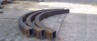
When using a profile pipe to create load-bearing structures, bending calculations must be performed. This type of rolled pipe is used in industrial, commercial and private construction. Canopies, all kinds of frame and stair structures, trusses, shelving, canopies, greenhouse structures, roofing system elements, and gazebos are made from it. Therefore, it is impossible to do without correct and careful calculations. Exceeding the permissible pressure will lead to deformation or rupture of the product at the bending point of the corrugated pipe.
Scheme 1
Using methods for calculating loads on a profile pipe, you can:
- maintain the original shape of the products;
- give the structure increased strength;
- increase the period of operation;
- minimize material costs;
- avoid negative destructive consequences.
We carry out pipe deflection calculations ourselves
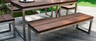
Profile pipes are common in industrial and private construction. They are used to construct outbuildings, garages, greenhouses, and gazebos. The designs can be either classically rectangular or ornate. Therefore, it is important to correctly calculate the pipe for bending. This will maintain its shape and ensure the structure’s strength and durability.
Properties of bendable metal
Metal has its own point of resistance, both maximum and minimum.
Maximum load on the structure leads to deformations, unnecessary bends and even breaks. When making calculations, we pay attention to the type of pipe, cross-section, dimensions, density, and general characteristics. Thanks to this data, it is known how the material will behave under the influence of environmental factors.
We take into account that when pressure is applied to the transverse part of the pipe, stress arises even at points distant from the neutral axis. The zone of most shear stress will be the one located near the neutral axis.
During bending, the inner layers in the bent corners are compressed and reduced in size, and the outer layers are stretched and lengthened, but the middle layers retain their original dimensions after the end of the process.
Bend pipes are widely used in daily life
How to make the right calculations
Calculation of a profile pipe for deflection is the determination of the degree of maximum stress at a specific point on the pipe.
Each material has normal stress indicators. They do not affect the product itself. To make the calculations correctly, you must apply a special formula. It is necessary to ensure that the indicators do not exceed the maximum permissible values. According to Hooke's law, the resulting elastic force is directly proportional to the deformation.
When calculating bending, it is also necessary to use the stress formula, which looks like M/W, where M is the bending indicator along the axis on which the force falls, but W is the bending resistance indicator along the same axis.
The pipe bend must be correct and precise
Bending process
Bending creates a certain degree of stress in the metal walls. Tensile stress is obtained in the outer section, and compressive stress in the inner section. Due to these influences, the tilt of the axis changes.
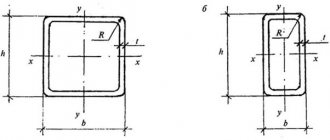
During the bending process, the cross-sectional shape changes at the bent point. As a result, the ring profile takes on an oval shape. A clearer oval shape is visible in the middle of the deflection, but towards the end and beginning the deformation decreases.
For pipes with a cross-section of up to 20 mm, the ovality in the deformed area should not exceed 15%. For pipes with a cross-section of 20 and larger - 12.5%.
Please note that folds may appear in the concave area of thin-walled products. They, in turn, negatively affect the functioning of the system (they reduce the permeability of the working medium, increase the level of hydraulic resistance, and the degree of clogging).
Curved pipes are used in industry and private construction
Allowable pipe bend radii
According to state standards, pipes have a minimum bending radius.
If bending is carried out by heating and filling with sand, the outer diameter of the pipe is at least 3.5DN.
Forming a pipe on a pipe bending machine (without heating) – at least 4DN.
Folding when heated with a gas burner or in an oven to obtain half-corrugated folds is possible with an indicator of 2.5DN.
If the bend is intended to be steep (for bent sewer branches made by hot drawing or stamping) - no less than 1DN.
The pipe bend may be less than the specified values. However, this is possible if the production method ensures that the pipe walls are thinned by 15% of the total thickness.
We carry out calculations of pipe bending strength responsibly.
Bending pipes of various diameters
Formulas and tables
To calculate pipe deflection, we determine the length of the part. It is calculated using this formula:
L=0.0175∙R∙α+l
R is the bending radius in mm;
α – angle value;
I – a straight section of 100/300, necessary for gripping the product (when working with the tool).
When calculating the bending of a profile pipe, we take into account the size of the element being bent. It is determined by the following formula:
А=π∙α/180(R+DH/2)
The value of the number π = 3.14;
α – bending angle in degrees;
R – radius value (the value is taken into account in mm);
DH is the diameter on the outside of the pipe.
The minimum bend radii for copper and brass products are given in the table. The data corresponds to State Standards No. 494/90 and No. 617/90. In addition, the values for the outer diameter and the minimum length of the statically free part are also given here.
Bending of profile pipes can be performed on special machines
| External diameter | Minimum bend radius | Minimum free length |
| 3 | 6 | 10 |
| 4 | 8 | 12 |
| 6 | 12 | 18 |
| 8 | 16 | 25 |
| 10 | 20 | 30 |
| 12 | 24 | 35 |
| 15 | 30 | 45 |
| 18 | 36 | 50 |
| 24 | 72 | 55 |
| 30 | 90 | 60 |
The following table will help you calculate a round pipe for bending. It includes data related to steel analogues (indicators correspond to State Standard No. 3262/75).
| Pipe sizes | Minimum bend radius | Minimum free length | ||
| Conditional pass | External diameter | Hot | Cold | |
| 8 | 13,5 | 40 | 80 | 40 |
| 10 | 17 | 50 | 100 | 45 |
| 15 | 21.3 | 65 | 130 | 50 |
| 20 | 26.8 | 80 | 160 | 55 |
| 25 | 33.5 | 100 | 200 | 70 |
| 32 | 42.3 | 130 | 250 | 85 |
| 40 | 48 | 150 | 290 | 100 |
| 50 | 60 | 180 | 360 | 120 |
| 65 | 75.5 | 225 | 450 | 150 |
| 80 | 88.5 | 265 | 530 | 170 |
| 100 | 114 | 340 | 680 | 230 |
In order not to make mistakes in the calculations, you should also take into account the diameter and wall thickness of the pipes.
| Pipe diameter (mm) | Minimum bend radius taking into account wall thickness | |
| thickness up to 2 mm | thickness more than 2 mm | |
| 5/20 | 4D | 3D |
| 20/35 | 5D | 3D |
| 35/60 | 6D | 4D |
| 60/140 | 7D | 5D |
Manual hydraulic pipe bender
DIY pipe bending
If you do the bending yourself, calculating the pipe for bending will help, the formula of which is simple and universal (this is 5 pipe diameters).
Let's calculate the bend on a part with a cross section of 1.6 cm.
1st step: you need to clearly understand what kind of circle the result will be (one fourth of the circle is needed for correct bending).
Step 2: determine the radius - multiply 16 by 5. Result - 80 mm.
3rd step: calculation of starting points for bending. To do this, use the formula C=2π∙R:4. Value C is the length of the pipe that will be used in the work. Two pi numbers are used, as well as an indicator of the outer radius of the pipe.
4th step: values are replaced with known data: 2∙14∙80:4. The result is 125 mm. This will be the length of the section where the minimum bending radius will be 80 mm.
How to find out the bending strength of a profile pipe
Profiled pipe is becoming an increasingly popular building material. It is used for the construction of building elements such as floors, load-bearing frames, and beams. Such widespread use is primarily due to the ease of construction, operation, and maintenance of structures, as well as the low weight of the products themselves.
However, it is important to remember that the profile pipe must have increased bending strength, and how to calculate it will be discussed later in the article.
We suggest using an online calculator to calculate beams of various sections made from pipes for bending.
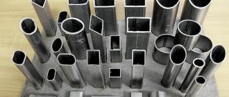
Features and properties of profile products
Profile are pipes that have a cross-section that is different from circular. The most common options are rectangular and square products. As already mentioned, the particular popularity of this type is associated with one of its key advantages - the design will be lightweight.
Moreover, the specific shape greatly simplifies attachment both to each other and to other surfaces. This type of building products, according to GOST, is made from a wide range of metals and alloys. However, the most commonly used are steel profiled pipes made of carbon and low-alloy steel.
Every metal has an important natural quality - a point of resistance. It can be either minimum or maximum. The latter, for example, causes deformation of erected structures, leads to kinks and, as a consequence, to fractures.
When bending, it is important to evaluate such characteristics as size, cross-section, type of product, its density, as well as the rigidity of the material and its flexibility. Knowing all these general properties of the metal, you can understand how the structure will behave during operation.
It is important to remember that when you bend the product, the internal parts of the structure are subject to compression, their density increases, and they themselves decrease in size. The outer layer, accordingly, becomes longer, less dense, but more stretched.
At the same time, the middle sections retain their original characteristics even after the process is completed. Hence, you should always remember that during the bending process, tension will certainly arise even in areas located as far as possible from the neutral zone. The maximum pressure will be in those layers that are very close to this very neutral axis.
What load acts on profile pipes?
Calculating the bending strength of a pipe comes down to a simple determination of the maximum stress at a particular point of the structure. It is important to understand what material the profile is made from, since each of them has its own voltage rating.
For correct calculations you need to use the correct formula. In this case, the provisions of Hooke's law are applied, which state that the elastic force is directly proportional to the deformation. The expression for calculations is as follows:
VOLTAGE = M / W, where:
- M is the value of the degree of bending along the axis along which the force is applied;
- W – bending resistance value taken along the same axis.
As already mentioned, each metal or alloy has its own normal stress values. It is the determination of these values that is one of the main tasks that you face when you decide to build a building from a profile.
In order to be sure that the results are correct, you need to know several important rules and, of course, follow them.
- Perform all calculations accurately, carefully, and slowly. At each stage, you should be guided by the appropriate formulas, without trying to adjust the values to those that are convenient for yourself.
- Having calculated the bending strength of a profile pipe, you should ensure that the obtained indicators do not exceed the established maximum values.
- Take into account the material from which the profile is made, the thickness of the walls, in order to prevent its destruction or deformation, which would complicate the functioning of the structure in the future.
- Before performing calculations, it is necessary to schematically depict the future element. Based on this technical drawing, more accurate calculations can be made, which will be insured against errors associated with an incorrect understanding of the shape of the structure.
Watch the video
By following all the necessary rules, as well as safety precautions, even a layman can be sure that all his results in calculating the bending strength of a pipe will be correct and the result will be successful. Constantly checking your calculations and monitoring at every stage of the work is the key to successful completion of the job.
Related posts:
: August 2, 2017
(5 4,20 of 5) Loading...
Source: https://trubanet.ru/stalnye-truby/raschet-prochnost-profilnojj-truby-na-izgib.html
Calculation of a square pipe for deflection and bending
Closed profiles, such as square, rectangular and round pipes, are an option for those who do not have the opportunity to use wooden structures, but want to give the future structure good aesthetics . For example, a canopy frame welded from square pipes looks more aesthetically pleasing than the same canopy welded from corners.
1. Calculator
2. Instructions for the calculator
On this page you are presented with a calculator capable of selecting the cross-section of a square pipe based on strength and deformation. In other words, using this calculator you can calculate a square pipe for deflection and bending in accordance with GOST 30245-2003 “Bent closed welded square steel profiles for building structures.”
You can calculate a square pipe for the following design schemes:
- Type 1 is a single span beam with a uniformly distributed load applied to it.
- Type 2 - rigidly clamped console with a uniformly distributed load.
- Type 3 - a beam lying on two supports with an extended console on one side.
- Type 4 is a single-span simply supported beam with a concentrated load applied to it.
- Type 5 is the same as Type 4, but with two concentrated loads.
- Type 6 - a console with rigid pinching with a concentrated load applied to it.
Instructions for the calculator
Please note that in non-integer numbers it is necessary to put a period, not a comma, that is, for example, 5.7 m, not 5.7. Also, if something is not clear, ask your questions through the comment form located at the very bottom.
Initial data
Calculation scheme:
Span length (L) - the span through which a beam or console length is thrown.
Distances (A and B) - distances from supports to places where loads are applied. For scheme 3, A is equal to the length of the beam console resting on 2 supports.
Standard and design loads are the loads for which a square pipe is designed. You can calculate them using the following materials:
F max is the maximum permissible deflection, selected according to Table E.1 of SNiP “Loads and Impacts”, depending on the type of structure. Some values of this indicator are given in Table 1.
Table 1. Maximum deflection for some structures according to SNiP.
| Type of beam | Span length | Requirements | Fmax _ |
| Beams for floors, coverings, roofs | L ≤ 1 m | Aesthetic and psychological, that is, those in which the deflection of the beam will not be “conspicuous” | 1/120 (1/60) |
| L = 3 m | 1/150 (1/75) | ||
| L = 6 m | 1/200 (1/100) | ||
| L = 12 m | 1/250 (1/125) | ||
| Beams of coverings and floors if they contain elements susceptible to cracking (screeds, floors, partitions) | any | Constructive | 1/150 (1/75) |
| Jumpers | any | Constructive | 1/200 |
| Notes:1. Without brackets, Fmax is indicated for the span, in brackets - for the cantilever.2. In the case of intermediate values of the span length L, the maximum deflection Fmax is found by linear interpolation. |
Number of pipes - usually one beam is indicated, but if you want to strengthen it and put another similar beam next to it, then you should select “two” in the column.
Calculator
| Calculation example |
Related calculators:
- Collection of loads on floor beams online.
- Calculation of a rectangular pipe
- I-beam calculation
- Channel calculation
- Angle calculation
- Calculation of a wooden beam
How to correctly calculate the load on a profile pipe using tables
Profile steel products are in demand in modern construction due to their long service life and ease of installation. Before purchasing pipes, it is necessary to calculate the load and bending strength in order to determine the type and quantity of materials.
Features of profile products
Profile pipes, which are widely used in the installation of various structures and laying communications, are a hollow elongated metal bar with a square or rectangular cross-section.
The material for the manufacture of profile products is high-carbon steel of various grades.
Profiled steel pipe serves as a material for the construction of frames of various designs:
- greenhouses;
- pavilions and stops;
- advertising structures;
- partitions;
- stairs;
- furniture, etc.
Also, a steel pipe can be used as a ceiling or beam.
Why are calculations needed?
Steel profiles assembled into a structure experience the load of other materials or substances, and also experience stress in the metal during bending. Exceeding the maximum permissible load results in deformation of pipe products or their rupture.
An incorrectly calculated load will lead to instability of the structure, impossibility of assembly or subsequent destruction. This is fraught with unnecessary financial costs for repairs, purchase of materials and restoration of the structure.
During operation of pipes under load, a number of changes occur in the structure of the metal, which must be taken into account when selecting products. When an external influence is applied to a product or it is bent, stress arises in the metal, i.e., uneven deformation occurs, in which compression of internal bonds between molecules and simultaneous stretching of the outer layer is noted. In this case, the internal parts of the metal increase in density, and the external parts decrease due to compaction at the point of impact.
What parameters are needed to calculate the load?
When selecting pipe profiles for the construction of structures, it is necessary to obtain information about the condition of the rolled pipe profiles to analyze the conditions and capabilities of the product during operation.
Data required for this:
- profile dimensions, mm;
- section shape;
- structural stress parameters;
- material strength indicators;
- type of load on the profile.
Thus, the resistance points for each type of material are taken into account. In this case, the maximum and minimum values are taken into account:
- The minimum indicators assume zero load.
- Maximum - with bending of the product to the point of rupture in the metal. Taking these values into account will allow you to correctly calculate stability and select pipes with appropriate parameters in order to increase the service life of the structure.
How to calculate load using tables
Taking into account various parameters, generally accepted mathematical calculations were made, which were compiled into single tables.
Anyone who wants to, according to the standards and rules, can calculate the permissible load using public reference tables and select the type of metal profile.
Note! The values in the reference materials were obtained by scientists and calculation bureaus using the theory of resistance of materials and the laws of physics.
The methodology for calculating loads on metal profiles according to approved tables is more accurate due to the following being taken into account in them:
- type of supports;
- presence of fastenings;
- type of loads.
Projects use lookup table data from document SP 20.13330.2011.
In cases where the structure does not have a load, the values are taken from Table 1 of the approved standard.
For example, for railings or decorative structures. Tables 2 and 3 contain indicators of the maximum load on the pipe profile, when the material can be deformed, but without rupture and when the impact stops, the metal element will return to its original shape and condition.
As the maximum load increases, the structure may break or collapse.
It is important! It is recommended to purchase steel profiles with a safety margin of at least 2 times the maximum permissible.
What load can profile pipes withstand?
According to approved standards, the load according to exposure time is classified into four groups:
- Constant. The profile is affected without changes in indicators. This could be other materials, soil, etc.;
- Temporarily long-term. The profile structure is subject to load for a long time. For example, when constructing plasterboard partitions, building stairs in private houses, etc.;
- Short-term. Rolled pipes experience seasonal or temporary loads. For example, the severity of snow, strong wind or rain pressure, the weight of furniture and visitors, etc.;
- Special. Load in case of natural disasters or emergencies. For example, during an earthquake, vehicle collision, etc.
Note! When calculating the load on a metal profile for erecting a canopy, it is important to remember that the product is a load-bearing structure.
To calculate the force on a metal profile frame, the following types of loads should be taken into account:
- weight and type of canopy material;
- type of snow cover and its depth;
- wind force;
- possibility of damage to the structure by vehicles.
Other types of payments
There are other methods for calculating the load on structures:
- using the formula for calculating the bending stress of a metal pipe: calculation of bending stress = bending moment of force / resistance
This formula uses Hooke's law about the proportionality of the elastic force to the deformation index.
- using special ready-made calculators.
Note! It should be remembered that using your own calculations using developed formulas may be fraught with errors and inaccuracies. Be careful when taking into account all indicators.
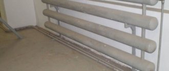
Geometric parameters of finned AVO pipes
| Fin coefficient | Outer diameter, mm | Rib height, mm | Number of ribs per 1 m linear length | Pipe length, mm |
| 9 | 49 | 10,5 | 286 | 12 000 |
| 14,6 | 56 | 14 | 333 | 12 000 |
| 20 | 57 | 15 | 400 | 12 000 |
| 22 | 57 | 15 | 433 | 12 000 |
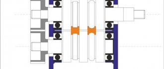
The widespread introduction of convective surfaces with transversely finned pipes (for example, various air cooler designs) in the energy sector and industry has become possible based on pipe finning methods using technologies:
- Knurling - a larger diameter pipe with a given thickness of aluminum is put on the supporting pipe, from which the ribs are subsequently extruded by deformation using machine rollers;
- Winding - an aluminum tape is wound tightly onto the supporting pipe, which can have several mounting options: in a groove or without.
By the way, read this article too: Air supply system At the same time, there are problems with accurate and universal methods for calculating their thermal and aerodynamic characteristics, further improving such surfaces, and intensifying heat transfer in them. The solution to these problems was to a certain extent hampered by the lack of a reliable physical picture of the transfer processes in transversely ribbed surfaces.