Parts, elements and geometric parameters of a twist drill
Twist drills are the most common.
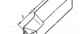
This drill (Fig. 309) consists of a working part, including a cutting part, a neck, a conical (Fig. 309, a) or cylindrical (Fig. 309, b) shank for fastening the drill in the machine spindle, a foot that serves as a stop for knocking out the drill from the spindle socket. The cutting part (Fig. 309, c) consists of two teeth formed by two grooves for removing chips; core - the middle part of the drill connecting both teeth; two front surfaces along which chips run and which absorb the cutting force; two ribbons - narrow strips along the outer diameter of the drill, serving to guide and center it in the hole; two main cutting blades formed by the intersection of the front and rear surfaces and performing the main cutting work; a transverse blade or bridge formed by the intersection of both rear surfaces. Rice. 309. Elements, geometric parameters and sharpening of spiral drills: 1 and 10 - ribbon blades; 2 and 6 — ribbons; 3 - two cutting blades; 4 and 8 — backs at the teeth; 5 - grooves; 7 - transverse blade; 9 - front surface.
A twist drill contains five blades: two main, two auxiliary (along the ribbons) and a transverse one, which does not cut, but crushes and squeezes out the metal. The cross blade of the drill has its main defect. The geometric parameters of the drill are considered on its cutting part.
The rear angle α is considered in the plane AA, parallel to the axis of the drill (Fig. 309, d), for the current point x (see section AA); it changes from αmin at the peripheral point of the drill to αmax, at the drill bridge.
The front angle γ is taken in the plane BB, perpendicular to the cutting blade of the drill (Fig. 309, d) for the current point x; this angle changes from γmin at the drill bridge to γmax at the peripheral point of the drill. The angle at the tip of the drill 2φ is between the main cutting blades: 2φ = 116 ÷ 118° when processing steel, cast iron, hard bronze; 2φ = 140° when processing aluminum and light alloys; 2φ = 80 ÷ 90° when processing ebonite, celluloid, marble.
The angle of inclination of the transverse blade ψ is 55º.
Drill sharpening. By sharpening the drill (Fig. 309, d) the following angle values are given: α min ≈ 7º, α max ≈ 26º, γ min ≈ 3º, γ max ≈ 30º.
The criterion for correct sharpening is compliance with the angles 2φ, ψ and α min.
In addition, it is necessary that the axis of the drill passes through the middle of the jumper and divides the apex angle of 2φ into two equal parts and that the main cutting blades are equal. To avoid pinching the drill on the drill, give a reverse cone towards the shank by an amount of approximately 0.05 mm per 100 mm length.
In Fig. 309, d single sharpening of the drill is given; in Fig. 309, e - double sharpening of the drill; in Fig. 309, g - single sharpening with sharpening of the transverse blade; in Fig. 309, h - single sharpening of the drill with sharpening of the ribbons. Double sharpening of the drill increases the durability of the drills, sharpening the jumper and ribbons facilitates the drilling process, reduces friction, and reduces the amount of feed force. With double sharpening there are angles 2φ and 2φ0; at 2φ = 116 - 118º, 2φ0 = 70 - 75°.
A bridgeless twist drill was proposed by the innovator V.I. Zhirov. Such drills are obtained from standard drills by using their special sharpening.
In the transverse blade (Fig. 310, c), the drills cut a groove with a grinding wheel, which significantly reduces the feed force.
Rice. 310. Bridgeless spiral drill designed by V.I. Zhirov.
Read also: DIY inverter semi-automatic circuit diagram
However, the best results (increased productivity and increased durability) are provided by a combined sharpening of the transverse drill blade (Fig. 310, b). Here, at a distance K equal to one third of the length of the cutting blade, the transverse blade is sharpened with an undercut of its core at an angle of 30°. The width of the cut groove a and the depth h are equal to 0.15 of the drill diameter.
It is necessary to ensure that sharpening is done efficiently. It is especially recommended to take drills with a double cone (Fig. 310, a).
Fig.21. Parts and elements of a twist drill.
1 – working part; 2 – cutting part; 3 – guide part; 4 – neck;
5 – shank; 6 – foot
The cutting part is the part of the drill sharpened to a cone. The working part is the part of the drill equipped with two spiral grooves. The guide part is the part of the drill that ensures the direction of the drill during the cutting process. The shank is the part of the drill that serves to secure the drill.
Fig.22. Main elements of the working part of the drill
1 – front surface; 2 – back surface; 3 – cutting edge;
4 – ribbon; 5 – transverse edge
The rake surface is the helical surface of the groove along which chips flow. Rear surface - the surface facing the cutting surface. Cutting edge - the line formed by the intersection of the front and rear surfaces; The drill has two cutting edges. Ribbon - a narrow strip on the cylindrical surface of the drill, located along the screw groove; Provides direction to the drill when cutting. Cross edge is a line formed by the intersection of both back surfaces.
Geometry of a twist drill.
The geometric parameters of the twist drill are shown in Fig. 23.
Fig.23. Geometry of a twist drill.
The angle 2φ (twice the entering angle) between the cutting edges varies widely depending on the material being processed. The inclination angle of the helical groove ω determines the rake angle and ranges from 100 to 45° depending on the material being processed.
Angle ψ – the angle of inclination of the transverse cutting edge is measured between the projections of the transverse and main cutting edges onto a plane perpendicular to the axis of the drill.
To determine the geometric parameters of the cutting edges, they are considered
1) in plane NN, perpendicular to the cutting edge;
2) in the OO plane, parallel to the drill axis. The front angle γ is considered in the NN plane.
The inclination angle of the helical groove ω and the clearance angle α are considered in
Cutting elements when drilling.
The cutting speed when drilling is the peripheral speed of rotation of the point of the cutting edge most distant from the axis of the drill.
Feed when drilling is the movement of the drill along the axis in one revolution. The feed rate is measured in millimeters per revolution
drill and is designated S mm/rev. Because the drill has two main cutting edges,
then the feed per each of them is Sz = S/2.
As with turning, feed can also be measured in mm. in 1 min. (minute feed)
Fig.24. Cutting elements when drilling.
a – cut thickness in mm, measured in the direction perpendicular to the cutting edge;
b – cutting width in mm, measured along the cutting edge;
t – depth of cut – distance from the machined surface of the hole to the axis of the drill t = D/2.
Milling.
Milling is one of the highly productive and widespread methods of metal cutting.
A cutter is a tool that has several teeth, each of which can be considered a cutter.
Fig. 25 Cutting part of the cutter.
When milling, the main (rotational) movement is carried out by the cutter, and the feed movement is carried out by the workpiece. Milling is used to process planes, grooves, shaped surfaces, and cut metals.
Geometry of cutters.
| Fig. 26 Geometry of the cutting part of the cutter. |
The cutter consists of a body (body) and cutting teeth. It is a multi-tooth cutting tool in the form of a body of rotation, on the forming surface or at the end of which cutting edges are located. There are angles of the main cutting edge of the tooth in a plane normal to the cutting lump, and angles in a plane normal to the axis of the cutter.
In the plane A-A, normal to the cutting edge, there are the main rake angle y and the normal rear angle αn. In the plane B-B, normal to the cutter axis, there are the main clearance angle α and the transverse or radial clearance angle γ'.
Read also: Chainsaw shoots into muffler reason
The main purpose of the rake angle γ is to reduce the work of plastic deformation and the work of friction along the rake surface during the cutting process and ensure the best durability of the cutting tool.
The main relief angle α is measured in the B-B plane, perpendicular to the cutter axis.
Rear Angle Purpose:
1. in creating conditions for unhindered movement of the rear surface of the tooth relative to the cutting surface;
2. in reducing the work of friction on the back surface of the tooth.
This page was last modified: 2016-08-01; Page copyright infringement
Drill
- a cutting tool designed for drilling holes in various materials.
Drills can also be used for drilling
, that is, enlarging existing, pre-drilled holes, and
drilling
, that is, obtaining blind recesses.
Parts and elements of a twist drill.
Fig.21. Parts and elements of a twist drill.
1 - working part; 2 - cutting part; 3 - guide part; 4 - neck;
5 - shank; 6 - foot
The cutting part is the part of the drill sharpened to a cone. The working part is the part of the drill equipped with two spiral grooves. The guide is the part of the drill that guides the drill during the cutting process. The shank is the part of the drill that serves to secure the drill.
Fig.22. Main elements of the working part of the drill
1 - front surface; 2 - rear surface; 3 - cutting edge;
4 — ribbon; 5 - transverse edge
The rake surface is the helical surface of the groove along which the chips flow. Rear surface - the surface facing the cutting surface. Cutting edge - the line formed by the intersection of the front and rear surfaces; The drill has two cutting edges. Ribbon - a narrow strip on the cylindrical surface of the drill, located along the helical groove; Provides direction to the drill when cutting. Cross edge is the line formed by the intersection of both back surfaces.
Geometry of a twist drill.
The geometric parameters of the twist drill are shown in Fig. 23.
Fig.23. Geometry of a twist drill.
The angle 2φ (twice the entering angle) between the cutting edges varies widely depending on the material being processed. The inclination angle of the helical groove ω determines the rake angle and ranges from 100 to 45° depending on the material being processed.
Angle ψ - the angle of inclination of the transverse cutting edge is measured between the projections of the transverse and main cutting edges onto a plane perpendicular to the axis of the drill.
To determine the geometric parameters of the cutting edges, they are considered
1) in plane NN, perpendicular to the cutting edge;
2) in the OO plane, parallel to the drill axis. The front angle γ is considered in the NN plane.
The inclination angle of the helical groove ω and the clearance angle α are considered in
Cutting elements when drilling.
The cutting speed when drilling is the peripheral speed of rotation of the point of the cutting edge most distant from the axis of the drill.
Feed when drilling is the movement of the drill along the axis in one revolution. The feed rate is measured in millimeters per revolution
drill and is designated S mm/rev. Because the drill has two main cutting edges,
then the feed per each of them is Sz = S/2.
As with turning, feed can also be measured in mm. in 1 min. (minute feed)
Fig.24. Cutting elements when drilling.
a is the cut thickness in mm, measured in the direction perpendicular to the cutting edge;
b is the cutting width in mm, measured along the cutting edge;
t - depth of cut - distance from the machined surface of the hole to the axis of the drill t = D/2.
Milling.
Milling is one of the highly productive and widespread methods of metal cutting.
A cutter is a tool that has several teeth, each of which can be considered a cutter.
Fig. 25 Cutting part of the cutter.
When milling, the main (rotational) movement is carried out by the cutter, and the feed movement is carried out by the workpiece. Milling is used to process planes, grooves, shaped surfaces, and cut metals.
Geometry of cutters.
| Fig. 26 Geometry of the cutting part of the cutter. |
The cutter consists of a body (body) and cutting teeth. It is a multi-tooth cutting tool in the form of a body of rotation, on the forming surface or at the end of which cutting edges are located. There are angles of the main cutting edge of the tooth in a plane normal to the cutting lump, and angles in a plane normal to the axis of the cutter.
In the plane A-A, normal to the cutting edge, there are the main rake angle y and the normal rear angle αn. In the plane B-B, normal to the cutter axis, there are the main clearance angle α and the transverse or radial clearance angle γ'.
The main purpose of the rake angle γ is to reduce the work of plastic deformation and the work of friction along the rake surface during the cutting process and ensure the best durability of the cutting tool.
The main relief angle α is measured in the B-B plane, perpendicular to the cutter axis.
Rear Angle Purpose:
1. in creating conditions for unhindered movement of the rear surface of the tooth relative to the cutting surface;
2. in reducing the work of friction on the back surface of the tooth.
What it is?
A drill is a tool element with a cutting edge that is used to drill holes in various materials. Milling cutters are made from high-strength steels, since the working part must be harder than the surface that needs to be drilled. In accordance with the purpose, each tool has its own characteristics and features; work can be carried out with wooden, metal, concrete, glass and tile objects and materials. The most common has become a twist drill, or in other words, a screw drill.
The device is presented in the form of a cylinder, consisting of three main parts:
- Working. It looks like two recesses arranged in a spiral along the cutter cylinder - this is the cutting structure. Thanks to this shape, chips are removed from the working surface. Also, if the equipment provides for the supply of lubricant, it will flow precisely along these grooves. The working part itself consists of two parts - cutting and calibrating (the second name is ribbon, this is a strip that continues the surface of the recess along the drill). The cutting structure consists of two main and two additional blades. The structural elements also include a cone-shaped transverse edge located at the end of the drill.
- Shank. This part is designed to secure the drill in the mill or tool for hand work.
- The neck of the cutter connects the working part and the shank, and markings are also applied to it.
Depending on the design, cutters are divided into the following types:
- cylindrical - general purpose drills, maximum diameter 80 millimeters;
- left-handed - the area of application is not so large, they are used for drilling broken bolts or other fasteners, differs from the standard in the direction of the screw notch;
- increased accuracy - they must have the symbol - A1. Their diameter is made with extreme precision, down to a fraction of a millimeter.
The way the drill will work, the position of the recesses, blades, and the inclination of the angles is determined using geometric parameters or its geometry.
The symbols for cutters of any diameter will always be the same. The angle of the drill tip between the main cutting blades, depending on how hard the surface being processed, varies from 90° to 120°. The inclination of the screw recess is measured by the outer diameter - this is from 18° to 30°. The inclination of the transverse edge at the end of the cutter is from 50° to 55°. In the main secant area, perpendicular to the main blade, the rake angle is measured, and in the plane parallel to the cutter axis, the back angle is measured.
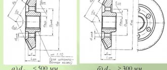
Twist drills with cylindrical and conical shanks: GOST 10902-77 and 10903-77
The most versatile and, accordingly, popular tools used to make holes in various materials are twist drills. Spiral drills are regulated by GOST 10902-77 and GOST 10903-77. Guided by the provisions of these regulatory documents, as well as the parameters of the hole that needs to be created, choosing the appropriate tool is quite easy.
Twist drills for metal
Design features and main characteristics
The design of twist drills, which are often called screw drills, consists of the following elements.
On the working part there are two grooves located along a helical line. They perform several functions simultaneously: they form the cutting part, remove the chips created in the processing zone, and provide coolant supply to the drilling area.
With the help of this structural element, the tool is fixed in the chuck of the equipment used. The shank can be made with a special foot, which makes it easier to remove the tool from a cone-shaped socket, or a leash, which is involved in transmitting torque from the chuck.
This technological element is responsible for the output of the abrasive wheel when it is used for tool grinding.
Main parts of the drill
The working part of a twist drill with a cylindrical or conical shank consists of several structural elements.
This element looks like a narrow strip that continues the groove on the working part. This guide part has another common name - “ribbon”.
This part is made up of five cutting edges: 2 main, 2 auxiliary, which are arranged in a spiral along the axis of the drill, and 1 transverse, located at the end of the tool and shaped like a cone. All of them are formed due to the intersections of groove surfaces. Thus, the main cutting edges are the intersection of the front surface of the tool groove with the rear, auxiliary - the front surface of the groove with the surface of the calibration part, transverse - the intersection of the rear surfaces of the ribbons.
Elements of the working part of the drill
The high popularity of twist drills is associated with their following advantages.
- Tools of this type have a large margin for regrinding the cutting part.
- Twist drills with a cylindrical or conical shank are characterized by better stability of their position during the drilling process.
- Due to the peculiarities of their design, such tools ensure timely removal of chips from the processing zone.
The main parameters of twist drills with cylindrical and conical shanks, the requirements for which are specified by GOST 10902 and GOST 10903-77, are listed in the table.
Table 1. Designation of the main parameters of drills
Geometric parameters of the cutting part of the drill
The values of all the above parameters are determined by the tasks for which the tool is planned to be used.
Twist drills are used not only for processing metal, but also for making holes in other materials such as concrete and wood. There are also general-purpose tools. Drills used for processing various materials differ from each other both in shape and design, as well as in their geometric parameters given in the relevant GOSTs.
Depending on the configuration of the part clamped in the chuck, drills are distinguished:
- with a cylindrical shank;
- with tapered shank.
To fix spiral drills with conical shanks on equipment, as indicated by GOST 10903-77, universal adapter bushings are used, the mounting holes in which are made of the “Morse cone” type. Tools of this type that comply with GOST can be used to equip any equipment.
Rules for storing drills
At workplaces of industrial enterprises, drills are stored in tool cabinets and bedside tables made of sheet metal, installed in the immediate vicinity of the machine, as well as on racks in special tool storage rooms. Drilling tools must be placed in a certain order (by type and diameter) in the appropriate compartments, cases or cases. Laying should ensure the safety of cutting edges, as well as working and seating surfaces. Before storing the drilling tool, clean it of metal dust and contaminants, and if not used for a long time, lubricate it with lithol or technical petroleum jelly. In order to prevent corrosion, it is prohibited to place acid-containing or other aggressive liquids near the tool storage areas. In home workshops, tools should be stored in compliance with the same rules. Only instead of bedside tables and cabinets, it is much more convenient to use plastic pencil cases and special stands (see video below).
When drilling deep holes in metal, it is recommended to pour a small amount of oil on the surface of the tool. I-20 is usually used in production, but not everyone has the opportunity to purchase this particular brand. What kind of oil can be used at home instead of industrial oil? Please share your thoughts and recommendations on this issue in the comments.
Drills with cylindrical shanks
Twist drills with a cylindrical shank, in accordance with the requirements of the regulatory document, can be produced in several series: short, medium and long. Using the appropriate GOST for drills, you can optimally select the tool to solve certain technological problems.
Cylindrical spiral drills, according to GOST, are manufactured with or without a centering hole. Tools of medium and long series, in accordance with GOST, may have a neck in their design, which facilitates their grinding. There are no special requirements for the size of such an element.
You can familiarize yourself with the GOST requirements for twist drills with a cylindrical shank by downloading the document in pdf format from the link below.
Metal drills with cylindrical shank
Left and right spiral instruments belonging to the short series and having a diameter from 0.5 to 40 mm are manufactured in accordance with GOST 4010-77. The production of right and left cylindrical drills of the middle series, the diameter of which is in the range of 0.25–20 mm, is regulated by GOST 10902-77. Long series twist drills are available in the diameter range 1–31.5 mm. The regulatory document that specifies the requirements for products in this series is GOST 886-77.
Drills with a cylindrical shank of a long series are produced mainly with a right-handed spiral direction. GOST allows the manufacture of products of this series in another design by agreement with the customer. The lengths of cylindrical shank spiral tools of all series are shown in the table below.
Table 2. Straight Shank Twist Drill Lengths
Technical requirements for the production of twist drills of all the above series are specified by GOST 2034-80. According to the provisions of this regulatory document, products of this series, which are used for drilling workpieces made of malleable and gray cast iron, carbon (structural and tool) and alloy steels, as well as structural steels of ordinary machinability and automatic machine, are made of high-speed steel alloys. Instruments in this series can belong to one of three accuracy classes:
- A1 (increased);
- B1 and B (normal).
Cylindrical shanks can have different designs
GOST allows that drills of this series can be made not from high-speed steel, but from alloy steel alloy grade 9ХС, while their shanks can be made from steel grade 45 or 40Х. According to their design, such drills can be either solid or welded. When using welding at joints, the presence of unwelded areas, voids and ring cracks is eliminated.
Drill bits with tapered shanks
Modern industry produces various types of drills, the shank of which has a conical shape. Accordingly, the requirements for such tools are regulated by different GOSTs. The unification of various types of drills allows them to be optimally selected for solving specific technological problems. The regulatory documents in accordance with the requirements of which spiral tools with tapered shanks are produced are:
- GOST 10903-77 (for products of normal length);
- GOST 12121-77 (for long series);
- GOST 2092-77 (for extended series);
- GOST 22736-77 (for products with carbide plates).
Metal drills with tapered shank for deep drilling
You can familiarize yourself with the GOST requirements for twist drills with a tapered shank by downloading the document in pdf format from the link below.
Twist drills of normal length, which are subject to the requirements of GOST 10903-77, can be produced in the diameter range of 5–80 mm. The shanks of such drills, depending on the diameter of the latter, have a normal or reinforced design. Spiral drills with a diameter of 12 to 76 mm are made with a reinforced shank. Their landing cone part corresponds to the Morse standard - from 1 to 6.
The diameter of long drills, according to GOST, can be in the range of 5–20 mm, while the processing performed with their help is carried out through jig bushings. The shank of such drills is made according to the Morse standard from 1 to 4. The spiral part of long drills and tools of normal length has a right direction, but by agreement with the manufacturer it can also be produced with a left direction.
Morse tapers with foot
Long drills with a tapered shank are produced with diameters of 6–30 mm. The tapered shank of such drills must comply with the Morse standard from 1 to 3.
Drills with a conical shank, on the metal rod of which carbide inserts of the VK type are soldered, can be produced with a diameter of 10 to 30 mm, in shortened and normal versions.
The lengths of the spiral tools with tapered shank of all series are shown in the table below.
Table 3. Taper Shank Twist Drill Lengths
The manufacturing materials for the main part of such drills are high-speed steel, steel alloy grade 9ХС or steel of other grades, which should not contain cobalt, and the amount of tungsten should not exceed 6%.
And in conclusion, a short video review of metal drills from various manufacturers with testing of these products in practice.
The best manufacturers
Among Russian manufacturers of drilling tools for metal work, the products of the Volzhsky Tool Plant (VIZ) and Tomsk Tool Plant have a good price-quality ratio. The tools of the Ukrainian Zaporozhye Tool Plant (ZIZ) belong to this category. The best quality drills are from world-famous manufacturers of cutting tools, such as German Bosch, Hasser and Ruko, Swedish Sandvik, Japanese Mitsubishi, Taiwanese Winstar, etc. But their products have a fairly high price and are intended mainly for professional use. In addition, metal drills are widely available on the market under the trademarks of well-known sellers and manufacturers of power tools. Basically, this is an inexpensive tool, but many products are of very high quality. In this category, users most often refer to Interskol, DeWalt, Hilti, Makita and Metabo.
Structural elements and geometry of a twist drill
A twist drill consists of a working part 1,
neck /3 and shank /4, which has a tab /5 at the end (Fig. 6.30).
The working part, in turn, is divided into cutting / 2 and calibrating / 2. The working part includes the following elements: ground strips (auxiliary cutting edges) 1,
transverse cutting edge
2,
grooves
3,
two main cutting edges
4,
front 7 and rear
5
surfaces , two teeth (feathers)
6
drills.
Rice. 6.30. Structural elements of a twist drill
The drill shank can be either conical or cylindrical with a driver.
In the first case, torque is transmitted due to friction forces between the conical surfaces of the drill shank and the spindle mounting hole, and in the second - through a driver. The foot is necessary for knocking out the drill from the machine spindle and transmitting torque at the beginning of cutting, when there is still no axial force and the friction forces are small. The neck is designed for the exit of the grinding wheel when making a drill. The calibrating part ensures the direction of the drill in the hole being drilled and is a reserve for the formation of the cutting part when it is re-sharpened.
The cutting properties of a drill are determined by geometric parameters and the material of its working part. The inclination angle of the helical flute is the angle between the axis of the drill and the unfolded helical line of the chip flute (Fig. 6.31, b).
Its value is not constant: the closer to the drill axis, the smaller the angle с. It is defined like this:
Rice. 6.31. Geometric parameters of a twist drill
where D -
drill diameter at the periphery;
Dx -
drill diameter corresponding to the current point L"; с is the angle of inclination of the helical groove, measured in a section parallel to the axis of the drill; for drills with diameters 0.25. 80 mm high-speed steel, the angle co is assigned depending on their diameter in the range from 17 to 34° (for smaller diameters the angle is smaller).
The inclination angle of the transverse cutting edge (jumper) y is contained between the projections of the transverse and one of the main cutting edges onto a plane perpendicular to the axis of the drill. Usually j/ = 50.55° (Fig. 6.31, a).
The cutting angle at the jumper is more than 90°, so the metal is not cut, but scraped.
Vertex angle 2ср (Fig. 6.31, a)
enclosed between the projections of the main cutting edges onto a plane passing through the drill axis (main plane). The magnitude of this angle depends on the properties of the material being processed and lies within the range of 80.140°. For drilling ductile materials, larger values of the angle 2f are taken than for brittle ones. For example, for processing steel and cast iron 2ср = 116.120°, for aluminum 2ф = 80, for hard-to-cut materials 2ф = 140°.
The auxiliary angle f1 is formed due to the execution of the working part of the drill with a reverse taper. Its value is 1... 2°. Auxiliary rear angles ots on the ribbons are equal to zero.
Main cutting edge angle X
is determined in the same way as for general purpose cutters.
The front angle y is the angle between the tangent to the front surface of the drill at the point in question and the normal at the same point to the surface of rotation, formed by rotating the cutting edge around the axis of the drill (Fig. 6.31, a).
At each point of the cutting edge in the
W
, the angle y has a different value, and in the
OO plane,
parallel to the drill axis, it is equal to the angle of inclination of the helical groove, i.e. yo = co.
From Fig. 6.31, b
it is clear that
where R is the pitch of the helical flute of the drill; I = const.
Dividing one equation by the other, we get
For comparison, the formula for determining the actual rake angle in a normal section N-N:
1) for the cutter tg up = tg y? sin = we have tg с = tg у • sin f. From here
Similarly, for the current point X
A joint solution of equations (6.35) and (6.37) gives
Analysis of the last formula shows that the rake angle has the greatest value at the periphery of the drill. Since in the axial section the angles y and с are equal to each other, for points of the cutting edge lying closer to the center, the rake angle yо is smaller than for the peripheral ones.
The back angle a is the angle between the tangent to the back surface of the feather at the point of the cutting edge under consideration and the tangent to the circle of its rotation around the axis of the drill (Fig. 6.31, a).
It is measured in plane
00,
parallel to the axis of the drill and tangent to the cylindrical surface on which a given point of the cutting edge lies. In a static state (by analogy with the value of the rake angle), the relief angle a, measured in the normal plane,
During the cutting process, the value of the clearance angle decreases, since the actual trajectory of the point lying on the main cutting edge will not be a circle, but a helical line with a step equal to the feed value. The cutting surface is a helical surface. Therefore, the actual back angle ad is determined between the tangents to this helical and back surfaces at the point in question. In its magnitude, it will be less than the value a by the value of the angle μ (Fig. 6.31, a):
As you approach the drill axis, the back angle a decreases, and for points of the cutting edge lying closer to the drill axis, for example, for point X,
the reduction in the main rear angle will be more intense than for the peripheral one. To ensure a sufficient clearance angle during the cutting process at points of the cutting edge located closer to the axis of the drill, the rear surface is sharpened so that at the periphery the angle a has a minimum value, and as it approaches the core it increases. Such sharpening is ensured by the design and kinematics of sharpening machines.
Since at the periphery of the drill the front angle of the drill is larger and the rear angle is smaller, and vice versa at the center, the sharpening angle remains approximately the same for all points of the cutting blade. The actual rake angle varies from 30° to zero and even negative at the web. The clearance angle at the periphery is 6.8°, and at the jumper 25.35 0.
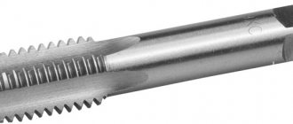
Twist drills
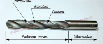
The most commonly used cutting tool for making holes in solid material is a twist drill. Along the entire length of the working part of the drill (Fig. 121, a) two helical grooves are made. The material left between the flutes is called the drill core.
The front surfaces (Fig. 121, b) of the helical grooves, intersecting with the occipital surfaces of the drill, form its cutting edges. The front surface of the drill groove, rising upward, seems to move back, as a result of which a front angle y is formed. The magnitude of this angle is not constant, since the front surface moves back more at points of the cutting edges located close to the side surface of the drill, and less at points close to its axis. For standard drills with a diameter of 10 mm and larger, this angle at the side surface of the drill is 30°, and at the axis of the drill it decreases to 1-4°. The back angle a of the side surface of the drill is made equal to 8-14° with a gradual increase to 20-26° near the axis of the drill. The larger of the indicated values of a refer to small, and the smaller - to large drill diameters.
Rice. 121. Twist drill and its elements
The angle A between the cutting edges of the drill is called the tip angle. The value of this angle for drills used in processing steel is 116-118°, when processing cast iron and hard bronze 90-100°, brass, duralumin and silumin 140°. If the drill is intended for processing various materials, its tip angle is made equal to 116-118°.
The transverse edge of the twist drill does not cut, but scrapes the material. The larger the diameter of the drill, the longer this edge and, as a result, the worse the operating conditions of the drill. In view of this, for drills of large diameters, the length of the transverse edge is slightly reduced by making points on both sides (Fig. 121, c) along the core of the drill. The angle α1 of the lift of the transverse edge of the drill, when sharpened correctly, should be about 55°.
The cutting edges of the drill must be straight, of the same length and must be located at equal angles to the axis of the drill. If these conditions are not met, the drill moves to the side during operation, and the hole it drills turns out to be larger than the diameter of the drill.
To reduce the friction of the drill on the side walls of the hole being drilled, part of the material on the outer surface of the working part of the drill is removed so that ribbons are obtained (Fig. 121, b). For the same purpose, the diameter at the tip of the drill is made slightly larger than that of the shank. This reduction in drill diameter is insignificant (only 0.04-0.10 mm for every 100 mm of drill length) and is due to the thickness of the ribbon; therefore, the reduction in hole diameter resulting from wear of the working part of the drill has no practical significance
The shank (Fig. 121, a) serves to secure the twist drill and can be conical or cylindrical.
Twist drills are made from tool carbon steel grade U12A and from high-speed steel. Drills equipped with plates made of metal-ceramic alloys are also used.
Drill sharpening . Sharpening of twist drills in well-organized factories is carried out on special machines, serviced by sharpening workers. If the sharpening of the drill is carried out by the turner himself, he must very carefully ensure that the above requirements for the cutting edges of the drill, the angles of inclination of the cutting edge and the rise of the transverse edges are met.
The correct sharpening of twist drills is checked using a template (Fig. 122, a). Checking the straightness of the cutting edges, their uniform length and the angles they form with the drill axis is shown in Fig. 122, b Checking the position of the transverse edge of the drill is shown in Fig. 122, c, and its sharpening angle is shown in Fig. 122, city
Rice. 122. Template for checking the correct sharpening of twist drills and its application
Varieties
The working part of the tool can be used for any materials and surfaces, therefore there is also a classification according to the material being processed.
- For metal. The type of drill is selected depending on the type of metal.
A metal cutter is a universal tool. In addition to cast iron, steel and various alloys, it can work on wood.
If during operation the tool works slowly and heats the metal, it is necessary to sharpen it. This is done manually if the diameter is up to 12 millimeters, and larger sizes are sharpened on a special machine.
- On concrete. Concrete is the most difficult to process; here you will need drills with special additional plates made of superhard alloys - pobeditovye. As a result of the work, the hole will be larger than the diameter of the cutter, this is explained by the runout of the structure.
To prevent the special plate from falling off during operation, it is necessary to monitor the heating.
- On wood. The simplest type of twist drill is made from high strength steel. The diameter varies from 2 to 20 millimeters, the standard length is from 49 to 210 millimeters.
It is distinguished from a tool for working with metal by the shape of the end piece - there is a spike for centering.