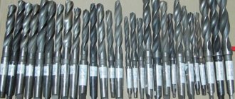
A gun drill is a tool that is used to drill through and blind holes of considerable depth. Holes of this type are made in shafts for various purposes, in spindles, as well as in other parts characterized by a significant length. For this purpose, not only gun drills are used, but also, in particular, single-edged and double-edged drills with internal chip removal. Drilling with the help of the latter is characterized by low productivity, but the deep holes made are characterized by high cleanliness, accuracy of geometric parameters and straightness.
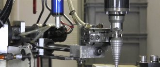
Deep drilling process on a turning-milling center
What is a gun drill and what is it used for?
A gun drill is a cutting tool of a predominantly cylindrical shape with a cross-section that varies along its length. It is a single-cut tool.
To remove waste chips from the workpiece, there is a recess on the surface of such a drill with a cross-section in the shape of the letter V. This groove is made along the outer surface of the drill.
In general, using a gun drill it is possible to produce holes with a diameter ranging from 0.5 millimeters to 10 centimeters. There is usually no special hole for supplying coolant. Drilling is carried out at a low speed of rotation of the metalworking unit.
In the working part, the gun drill has the shape of a semicircle. The flat surface of the semicircular rod is the front surface of the drill. At a right angle to the axis of the drill, a cutting edge is formed at the end of the rod. The rear end of the tool has a flat, inclined shape at an angle of 10-20 degrees.
To ensure more precise guidance, the supporting surface of the gun drill is cylindrical. On the supporting surface, flats are made at 35-40 degrees, as well as a reverse cone of 0.04-0.05 millimeters per 10 centimeters of length. These measures help reduce friction between the tool and the internal walls of the workpiece.
To remove chips formed during the cutting process, you have to regularly remove the drill from the part. The geometry of the drill contributes to the harsh operating conditions of the tool, which reduces its durability and reduces the accuracy of the cutting process.
Note that in modern metalworking there are more accurate and productive ways to produce deep holes. Processing a part with a gun drill is considered an outdated and ineffective method of deep drilling.
ACCEPTANCE RULES
2.1. Acceptance rules - according to GOST 23726.
2.2. Testing of drills for the average durability period is carried out once every three years, for the 95% durability period once a year, on at least 5 drills.
2.3. Drills of accuracy classes A1 and B (or B1) of the same standard size from each range of diameters, mm: from 0.25 to 3.0 must be tested; St. 3.0 to 11.0; St. 11.0 to 18.0; St. 18.0 to 23.0; St. 23.0 to 80.0.
2.2; 2.3. (Changed edition, Amendment No. 3).
Types of drills for deep drilling
In today's metalworking technology, several types of drills are used for deep drilling of parts.
Let's look at their main types:
- Gun drills. The characteristics of this type of drill were discussed above. Recently, an instrument has been produced with a slightly modified form in relation to the traditional one. This allows you to increase the productivity of the process and the quality of the processed parts. It makes sense to use gun drills when machining small-diameter holes. The length of the holes is usually no more than 40 diameters. Accuracy according to IT9, and surface finish is 0.09 - 3.5 microns.
- Gun drill made as one piece. They are also called monolithic drills because they are made entirely of carbide material. There is a special passage inside the drill to supply coolant. Chips and coolant are removed from the part through an external helical groove. They are used for drilling holes up to 100 millimeters. Depth – up to 100xD. The tool received this name because it was previously used to process firearm barrels.
- Gun drill, made using the technology of fixing cutting plates made of hard alloy by soldering. Like other drills of this type, they provide high dimensional accuracy with minimal deviation of the drilling axis.
- A gun drill with additional cutting inserts. Such drills make the cutting process more productive.
- Twist drills with cylindrical shank. Manufactured in accordance with the requirements of GOST 886-77. They have an elongated cutting part, which can be made entirely of high-speed steel or have carbide inserts. The coolant supply can be either from the inside or from the outside. The shank may also have a cylindrical shape.
- Feather drills. They are used for drilling shallow stepped holes.
- Ejector drills. Used for drilling deep holes in metalworking machines with the cutting tool placed in a horizontal plane.
GOST 10902-77 Spiral drills with a cylindrical shank. Average series. Main Dimensions
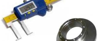
A drill with a tapered shank is called a conical drill. It is a popular cutting tool in production and at home. The product is securely mounted in a hand tool chuck or equipment spindle (lathe, milling, universal) and ensures centering accuracy. This allows you to avoid burrs during drilling, drilling and reaming operations and obtain a perfectly smooth inner surface. In addition, a drill with such a shank is easy and simple to change in case of dullness or breakage. Products with a cone-shaped shank are used for metal work. With their help, holes of different diameters are made in alloy and carbon steels, gray, ductile and high-strength cast iron, non-ferrous and metal-ceramic alloys, and other durable and hard materials. Conical type tools are produced in accordance with the requirements of Russian and foreign standards GOST 10903-77, DIN 345, ISO 296.
Important Features of Deep Hole Drilling
Deep drilling of holes in metal is a specific metalworking process and requires an appropriate approach. This operation should be performed on deep drilling machines specially designed for this purpose.
An important feature of the process is the precise centering of the tool and the elimination of drill deviation along the axis. It is necessary to avoid tool runout. To obtain a hole with precise dimensions and a high-quality surface, it is important to provide the processing area with a sufficient amount of coolant.
Chip removal grooves must be smooth to ensure timely removal of chips from the processing area.
Drilling blind holes differs in the direction of complexity in that during the work you need to constantly monitor the depth of the hole. For deep holes this causes some difficulty.
TEST METHODS
3.1. Tests of drills for performance, average and 95% durability periods are carried out on drilling, milling, lathes with mechanized feed using auxiliary tools, which must meet the standards of accuracy and rigidity established for them.
3.2. Drills must be tested on samples made of steel grade 45 according to GOST 1050, hardness 187 ... 207 HB by drilling blind holes with a depth equal to three diameters, but not more than 85 mm.
The roughness parameter of the sample surfaces should not be more than, µm:
| for drills up to 2.95 mm diameter Ra 0,8 for drills with a diameter of St. 2.95 mm Rz 40 |
3.3. A 5% by weight solution of emulsol in water with a flow rate of at least 5 l/min or oil coolants should be used as a cutting fluid.
3.4. When drilling holes with a diameter of up to 1 mm, the surface of the workpiece can be pre-cored.
3.5. Tests of drills must be carried out in the modes specified in table. 8.
3.6. After performance testing, the cutting edges of the drills should be free of chips and chips, and the drills should be suitable for further work.
3.7. Acceptance values for the average and 95% durability periods must be no less than those indicated in the table. 9.
3.8. The hardness of drills is controlled using devices in accordance with GOST 23677.
Table 8
| Drill diameter, mm | Cutting speed for series drills, m/min | Feed for drills, mm/rev | Number of holes in performance tests | ||
| short and normal | long and elongated | short and normal | long and elongated | ||
| From 0.26 to 0.5 | 12 | — | 0,004 | — | 30 |
| St. 0.6 to 0.7 | 14 | 0,006 | |||
| St. 0.7 to 0.9 | 15 | 0,008 | |||
| St. 0.9 to 1.1 | 20 | 16 | 0,010 | 0,008 | |
| St. 1.1 to 1.4 | 21 | 0,015 | 0,012 | 25 | |
| St. 1.4 to 1.8 | 18 | 0,020 | 0,015 | ||
| St. 1.8 to 2.2 | 0,025 | 0,020 | |||
| St. 2.2 to 2.8 | 23 | 20 | 0,030 | 0,025 | 22 |
| St. 2.8 to 3.0 | 25 | 0,040 | 0,030 | ||
| St. 3.0 to 5.0 | 29 | 23 | 0,100 | 0,070 | 20 |
| St. 5.0 to 7.0 | 0,140 | 0,100 | 18 | ||
| St. 7.0 to 9.0 | 0,170 | 0,140 | |||
| St. 9.0 to 11.0 | 28 | 22 | 0,200 | 0,170 | 15 |
| St. 11.0 to 14.0 | 0,220 | 0,170 | |||
| St. 14.0 to 18.0 | 0,250 | 0,200 | 12 | ||
| St. 18.0 to 23.0 | 0,280 | 0,220 | 10 | ||
| St. 23.0 to 30.0 | 0,320 | 0,250 | 6 | ||
| St. 30.0 to 35.0 | 27 | 21 | 0,400 | 0,280 | 4 |
| St. 35.0 to 45.0 | — | 0,430 | — | 4 | |
| St. 45.0 to 60.0 | 0,560 | 3 | |||
| St. 60.0 to 80.0 | 25 | 0,800 | 3 | ||
Notes:
1. For drills made of 9ХС steel, the correction factor for cutting speed and feed is 0.5.
2. If the machine does not have the required feed S (mm/rev), rotation n (min-1), it is allowed to select the nearest S and n, provided that the minute feed Smin = n ∙ Sob differed by no more than 10% from that calculated according to the data specified in table .
Table 9
| Drill diameter, mm | Acceptance durability periods, min | |||
| average | installed | |||
| A1 | B1, B | A1 | B1, B | |
| From 0.25 to 0.5 | 8 | — | 2,3 | — |
| St. 0.5 to 0.7 | 9 | 2,8 | ||
| St. 0.7 to 0.9 | 12 | 3,5 | ||
| St. 0.9 to 1.1 | 16 | 11 | 4,5 | 2,8 |
| » 1,1 » 1,4 | 20 | 14 | 6,0 | 3,5 |
| » 1,4 » 1,8 | 23 | 16 | 7,0 | 4,0 |
| » 1,8 » 2,2 | 26 | 18 | 8,0 | 4,5 |
| » 2,2 » 2,8 | 29 | 21 | 9 | 5,0 |
| » 2,8 » 3,0 | 33 | 23 | 10 | 6,0 |
| » 3,0 » 5,0 | 34 | 24 | 15 | 8 |
| » 5,0 » 7,0 | 36 | 25 | 16 | 9 |
| » 7,0 » 9,0 | 41 | 28 | 18 | 10 |
| » 9,0 » 11,0 | 49 | 34 | 22 | 12 |
| » 11,0 » 14,0 | 58 | 40 | 26 | 14 |
| » 14,0 » 18,0 | 64 | 45 | 29 | 16 |
| » 18,0 » 23,0 | 76 | 51 | 35 | 18 |
| » 23,0 » 30,0 | 82 | 56 | 37 | 20 |
| St. 30.0 to 35.0 | — | 62 | — | 22 |
| » 35,0 » 45,0 | 68 | 24 | ||
| » 45,0 » 60,0 | 74 | 25 | ||
| » 60,0 » 80,0 | 85 | 30 | ||
3.9. The appearance of drills is checked visually.
3.10. The surface roughness parameters of drills are checked by comparison with roughness samples in accordance with GOST 9378 or with standard tools having values of surface roughness parameters not exceeding those specified in clause 1.11 using a magnifying glass LP-1 - 2´ in accordance with GOST 25706.
3.11. When monitoring drill parameters, control methods and means must be used, the error of which should not be more than: when measuring linear dimensions - the values specified in GOST 8.051; when measuring angles - 35% of the tolerance value for the angle being tested; when monitoring the shape and location of surfaces - 25% of the tolerance value for the parameter being tested.
3.12. For drills with a diameter of 3 mm or more, accelerated tests for the average durability period are allowed.
When carrying out accelerated tests of five drills at the modes specified in paragraph 3.11, wear on the flank surface is measured after operating time t.
The time values t and permissible average wear h should be no more than those indicated in the table. .
Table 10
| Drill diameter, mm | Test time for drills of accuracy classes, min | Average wear, mm | |
| A1 | B1, B | ||
| From 3 to 5 | 17 | 12 | 0,18 |
| St. 5 » 7 | 18 | 12,5 | 0,24 |
| » 7 » 9 | 20,5 | 14 | 0,30 |
| » 9 » 11 | 24,5 | 17 | 0,33 |
| » 11 » 14 | 29 | 20 | 0,36 |
| » 14 » 18 | 32 | 22,5 | 0,48 |
| » 18 » 23 | 38 | 25,5 | 0,54 |
| » 23 » 30 | 41 | 28 | 0,60 |
| » 30 » 35 | — | 25 | 0,40 |
| » 35 » 45 | — | 27 | 0,50 |
| » 45 » 60 | — | 30 | 0,60 |
| » 60 » 80 | — | 34 | 0,80 |
(Introduced
additionally, Amendment No. 3 ).
Deep Hole Tool Selection
First of all, the deep cutting tool must match the unit on which you are going to perform cutting operations. The shank must match the chuck of the machine tool or machine gun. Moreover, drills for deep drilling must be installed on units specially designed for these operations.
If during processing you need to strictly eliminate axis deviation while maintaining high accuracy, it is better to use a solid carbide gun drill.
If the material being processed breaks into long chips during processing, a tool with chip flutes with a high surface finish should be used. When working with aluminum alloys, use a tool with a single blade and a 180-degree sharpening of the cutting edge.
Otherwise, you should choose a tool depending on the length and diameter of the required hole.
Drill markings
Metric cutting tools are produced by cone numbers: 4, 6, 80, 100, 120, 160, 200, where the numbers indicate the largest cone diameter in mm. Products with a Morse taper are designated by numbers (0, 1, 2, 3, 4, 5, 6) and differ in the size of the largest diameter, respectively 9.045; 12.065; 17.78; 23.825; 31.267; 44.399 and 63.348 mm. Markings are placed on the tail section. Usually indicate the grade of steel or type of material from which the product is made, diameter and length. The name of the manufacturer and other data provided for by the regulatory and technical documentation can be applied to large-diameter cutting tools.
Basic steps for drilling deep holes
Drilling deep holes in metal is usually performed in the following sequence:
- A preparation hole with a slightly smaller diameter with a tolerance of H8 is drilled into the part.
- The main processing tool is started at low speed and slowly moved towards the end of the part.
- Gradually bring the tool to the speed required by the technology and begin supplying the lubricant and cooling liquid.
- Drill the part to the required depth. In this case, the tool is not removed from the hole.
- If the technology uses a tool of considerable length, then the first quarter of the cut is performed at a reduced rotation speed. The rest of the hole is cut at rated speed.
- When the required depth is reached, the supply of lubricant is stopped.
- coolant to the tool.
- Then the drill is quickly removed from the drilling area and the operation of the unit is stopped.
This technology is standard and may differ depending on the tool used and metalworking equipment.
Types of tapered shanks for drills
Structurally, the product consists of the following main parts:
- working part, which can be of very different shapes;
- guide part;
- leash;
- necks;
- conical shank.
Most often, spiral products are used, which are suitable for chucks and spindles of household and industrial tools and machine tools. They are produced with a diameter from 5 to 80 mm.
The shank, although it has the shape of a cone, as reflected in its name, can be made in metric (taper 1:20 with an angle of 1°25′56″) and Morse taper (taper from 1:19.002 with an angle of 1°25′43 ″ to 1:20.047 with an angle of 1°30′26″). They are also distinguished by the following characteristics:
- material of manufacture (carbon steel, high-speed steel, alloy steel);
- designs (with or without a tip, with or without a thread, a foot);
- execution series (short, medium);
- manufacturing accuracy (normal, increased).
Adaptations
Manual or automatic cutting methods provide results in various classes of accuracy and roughness. Thus, the main tool remains a tap, which is a rod with cutting edges.
- manual, for metric (M1-M68), inch - ¼-2 ʺ, pipe - 1/8-2 ʺ;
- machine-manual - attachments for drilling and other machines, used for the same sizes as manual ones;
- nuts, which allow you to cut a through version for thin parts, with nominal sizes of 2-33 mm.
- For cutting metric threads, use a set of rods - taps:
- rough, having an elongated intake part, consisting of 6-8 turns, and marked with one mark at the base of the shank;
- medium - with a fence of average length of 3.5-5 turns, and markings in the form of two marks;
- the finishing part has a fence of only 2-3 turns, without marks.
Read also: Semi-indirect connection of a three-phase meter
Tolerance control of metric thread placement
When cutting manually, if the pitch exceeds 3 mm, then use 3 taps. If the product pitch is less than 3 mm, two are enough: roughing and finishing.
Taps used for small metric threads (M1-M6) have 3 grooves that carry chips and a reinforced shank. The design of the others has 4 grooves, and the shank is through.
The diameters of all three rods for metric threads increase from rough to finish. The last threaded rod must have a diameter equal to its nominal diameter.
The taps are attached to special devices - a tool holder (if it is small) or a crank. They are used to screw the cutting rod into the hole.
Preparing holes for cutting is carried out using drills, countersinks and lathes. It is formed by drilling, and by countersinking and boring it is increased in width and improves the quality of the surface. The fixtures are used for cylindrical and conical shapes.
A drill is a metal rod consisting of a cylindrical shank and a helical cutting edge. Their main geometric parameters include:
- the helical lift angle is usually 27°;
- point angle, which can be 118° or 135°.
Drills are rolled, dark blued, and shiny - ground.
Countersinks for cylindrical shapes are called counterbores. They are metal rods with two cutters twisted into a spiral and a fixed guide pin to insert the countersink into the cavity.
Step drill 5-35 mm vs getinax. Drill out and maintain alignment.
A gun drill is a tool that is used to drill through and blind holes of considerable depth. Holes of this type are made in shafts for various purposes, in spindles, as well as in other parts characterized by a significant length. For this purpose, not only gun drills are used, but also, in particular, single-edged and double-edged drills with internal chip removal. Drilling with the help of the latter is characterized by low productivity, but the deep holes made are characterized by high cleanliness, accuracy of geometric parameters and straightness.
Deep drilling process on a turning-milling center
How to choose the right tool
When choosing drills for deep drilling, you should consider a number of factors:
Scheme for calculating drill length when working on a universal machine
It should be borne in mind that the device on which such a drill will be installed must be designed specifically for deep drilling.
Before starting drilling, you should select the optimal speed of rotation and feed of the cutting tool, as well as ensure its effective cooling. For materials that produce long chips when cutting, it is best to use a drill with polished flutes.
Gun drills can be single- or double-sided cutting
Step drill 5-35 mm vs getinax. Drill out and maintain alignment.
I don’t like step drills with a standard 6.3 mm hex shank, firstly, it is not power-operated, and secondly, there is no need for it. Therefore, the order was made in favor of a cylindrical shank.
The drill arrived simply in a package, and was not damaged by the naked eye:
Compared to the inch one, the coating is different, the shank is shorter and the diameter is larger - 13 mm versus 9.5 mm for the inch one. In addition, I like the inch shank because it has 3 wide edges:
One of the applications, as I said, is to drill holes without disturbing the alignment. As an example, there is a central hole for a 6.3 mm crown:
It is required to drill it on both sides by 15 mm and 12 mm to a certain depth while maintaining alignment and neatness of the edges, for example, for fitting on a shaft:
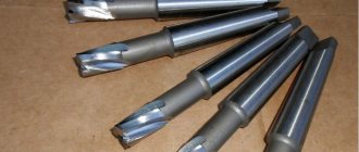
Morse taper drills
Such products, according to current standards, are produced in the usual version in eight sizes (KM0÷KM7, which corresponds to the cone number from 0 to 7) and nine in a shortened version (B7, B10, B12, B16, B18, B22, B24, B32, VA45, where the number in the designation corresponds to the largest diameter in mm). This allows you to select a drill for any equipment or tool on which the drilling operation will be performed.
The video clearly shows a cutting consumable tool with an extended Morse taper shank:
We ask those who have worked with drills with a conical shank to share their experience in the comments to the text, and also tell us about the tool, equipment, and devices used (adapter, collet) with which the drilling operation was carried out.
How to choose the right tool
When choosing drills for deep drilling, you should consider a number of factors:
Scheme for calculating drill length when working on a universal machine
It should be borne in mind that the device on which such a drill will be installed must be designed specifically for deep drilling.
Before starting drilling, you should select the optimal speed of rotation and feed of the cutting tool, as well as ensure its effective cooling. For materials that produce long chips when cutting, it is best to use a drill with polished flutes.
Gun drills can be single- or double-sided cutting