Home Blog Machine tooling: types and features
Machine tool equipment is understood as devices designed to expand the functionality of machine tools when solving various production problems. As a rule, they are not included in the standard equipment. These can be all kinds of bushings, cutter holders, chucks for securing parts, drills and other accessories.
Definition and types of turning
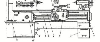
During turning, the cutting tool impacts the part. In this case, two types of movement are performed in the machine - rotational (for the workpiece) and translational (for the cutter). In this way, excess material is removed and the required shape is transferred to the processed component.
To perform the above operations, the design of the machine has mandatory elements - front and tailstocks, a support and a tool holder. With their help, the tool is positioned relative to the part, and the parameters of certain types of processing are set.
Depending on the desired result, the following types of turning are distinguished:
- grinding. Divided into external and internal. Using a cutter, material is removed from the surface of the part;
- boring. The essence of this function is to increase the diameter or change the configuration of the hole. Special types of cutters are used;
- turning cones. The operation is similar to the turning procedure, the difference lies in the location of the cutting tool. It is installed at a certain angle relative to the surface;
- thread formation. This requires a special design of the caliper apron;
- grooving and cutting. Special types of cutters are used;
- cutting ends.
These are the most common types of turning work. They can be performed on one machine, if this is provided for by its design. But to achieve optimal results, you need to know the technical characteristics of the equipment. They affect the quality and accuracy of work.
If complex processing of parts is expected, it is recommended to use a turret-type tool holder. Several types of processing tools can be located on it; the change occurs due to the rotation of the working head.
Specifics of equipment for CNC milling machines
Modern milling machines (including milling equipment) have specific features, which largely determine the range of simplified equipment used. In particular:
- The design and location of spindles of milling equipment allows you to forget about the need to remove and reinstall the product in three planes. Using several spindles or one with a rotating head, a modern machine saves space in production facilities and time for manufacturing the product. All this has a positive effect on production efficiency as a whole;
- Rotating lathe chucks optimize cutter access to the workpiece and increase surface coverage. This provides a number of advantages in the field of three-dimensional processing and decorative milling, regardless of the material of the workpiece being processed;
- High precision in the production of the final product and its compliance with sample dimensions down to a micrometer are ensured by linear movement modules.
All of the above design features make it possible to significantly optimize the milling process on a CNC machine. This is especially effective in mass production of products on various scales.
Factors affecting the quality of operations
When choosing a specific type of turning equipment, it is necessary to study its functionality in detail. They determine not only the list of operations performed, but also the accuracy.
The determining parameter is the characteristics of the workpiece - dimensions and weight. Depending on this, it can be fixed in the centers or above the frame. At the next stage of analysis, it is necessary to find out the maximum turning length. When processing the internal surfaces of parts, the maximum permissible depth is determined. It depends on the configuration of the cutter, as well as the parameters of the feed mechanism.
In addition, the following factors influence the quality of turning:
- spindle head rotation speed;
- number of speeds;
- caliper characteristics - the value of longitudinal and transverse feeds, maximum and minimum displacement parameters;
- type of cutters installed and their mounting dimensions;
- rated power of the main drive motor.
All these parameters must be taken into account when drawing up a technological diagram of the production process. In addition, the quality of processing is affected by the degree of equipment automation. For optimal results, it is recommended to use CNC machines.
Additionally, it is necessary to take into account the nature of the chips being formed. It can be merged, elementary, with a break or stepped. This will affect how it is removed, as well as the degree of coolant treatment required.
Machine tooling for turning
In addition to the main components of the equipment, in some cases special equipment will be needed to perform turning work. It can be included as standard on the machine, or installed as an option. In this case, turning can be performed in non-standard modes.
One of the defining components is the parts fixation mechanisms. Traditionally, the workpiece can be mounted between the headstock and the rear drive stock. This takes into account the configuration of the locking chuck, as well as the parameters of the tailstock quill.
To increase the functionality of the equipment, the following additional components of the lathe can be used:
- clamps. Designed to transmit torque when securing parts in centers;
- pressure Installed on the tool holder and is necessary to increase the accuracy of tool positioning;
- lunette. Used for turning work with large workpieces. This device serves as an additional fixing element.
In addition to these devices, various others can be used. It all depends on the requirements for the quality of operations, as well as the parameters of the processing flow chart.
As an example, you can watch a video that shows high-tech turning of a part:
Auxiliary tools and accessories for milling machines
Due to the complex configurations of workpieces that are processed by milling on CNC equipment, the range of equipment used for such machines is significantly larger than for lathes.
Universal equipment includes jaw chucks, yews and other devices. Magnetic plates and vacuum tables provide efficient workpiece clamping. Rotary tables, which can be equipped with certain models of such equipment, allow you to process a part from several sides.
When ordering one or another milling and engraving machine from the Daedalus series from Mirtels, you can also check with our managers for the necessary list of tools and equipment for the manufacture of the products you are interested in.
UNIVERSAL NON-ADJUSTMENT EQUIPMENT
(TG
Despite the huge variety of special machine tool equipment used in mechanical engineering
,
there is a fairly large range of universal equipment, the use of which allows, at low cost, to significantly save auxiliary time and increase labor productivity. Some of this equipment is supplied with the equipment, the other part is freely sold by specialized companies. Let's consider some types of such universal (non-adjustment) equipment.
Purpose and features
Machine tooling opens up new technological possibilities that allow you to perform operations that are unusual for some production machines. For example, a small re-equipment of a milling machine can turn it into a planer or slotter. Thus, the use of such devices significantly expands the range of manufactured products without the need to purchase additional expensive equipment.
The versatility of machine equipment is ensured through the use of standard fasteners suitable for various machines and the unification of connecting fittings. There are also highly specialized products designed to solve specific production problems. Devices of this type are often produced by the same plants and factories that produce machine tools.
Accessories for lathes
On lathes, workpieces such as shafts are mounted in the centers along the center holes. One center is located in the headstock spindle, and the second is located in the tailstock quill of the lathe. The chuck is installed and secured at the end of the machine headstock spindle.
The centers are divided into the following types:
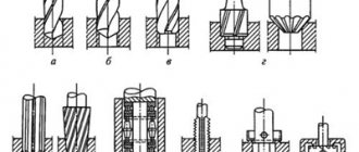
- 1) fixed normal and special (Fig. 4.1);
- 2) rotating normal and special (Fig. 4.2, 4.3);
- 3) special corrugated (Fig. 4.1, d
); - 4) cut (Fig. 4.1, c).
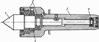
The conical surface of the center is intended for installing the part and has an apex angle of 60, 90, 120°; The center shank is made with a Morse taper of a certain number (No. 0, 1,2, 3, 4, 5, 6).
The non-rotating centers of machine tools become very hot and wear out due to friction; used for roughing at low rotation speeds. To reduce wear and increase their service life, rotating rear centers are used, which are less accurate than non-rotating ones. Rear center
(Fig. 4.2) are used to install workpieces with center holes, and the rear center shown in Fig. 4.3, - for processing blanks of hollow parts.
Rice. 4.1.
Various types of turning centers:
1,2
and
3
- working, tail and supporting parts, respectively
Rice. 4.2.
Rotating rear center design
Rice. 4.4.
Floating front center
When processing stepped shafts on multi-cutting machines to obtain specified linear dimensions, the shaft blank is mounted on a floating (spring-loaded) front center.
In Fig. Figure 4.4 shows a diagram of such a spring-loaded center: center 2
is recessed into body
1
under the action of the workpiece, pressed by the rear center. The end of the part always occupies a fixed position, determined by the end of the body /.
Rice. 4.5.
Three-jaw self-centering chucks
Rice. 4.3.
Mushroom back center design for installing hollow shafts
To clamp parts on the outer cylindrical surface, a variety of self-centering and driving chucks are used.
Three-jaw self-centering lathe pagrons (Fig. 4.5) are produced in accordance with GOST 2675-80 in the following sizes: 80, 100, 150, 200, 250, 315, 400 and 500 mm (outer diameter). Equipped with a spiral-rack mechanism, they ensure clamping and centering of the workpiece along the axis of rotation of the chuck with an error of 0.05. 0.15 mm. The clamping time in such a chuck ranges from 0.3 to 0.9 minutes. The clamping is carried out with a special key with a square. The cams are used raw and hardened, they can also be replaceable.
For mechanized clamping, self-centering three-jaw wedge quickly adjustable chucks are used, the designs of which are shown in Fig. 4.6. They are designed for basing and securing workpieces such as shaft and disk when processing on lathes.
Rice. 4.6.
Self-centering three-jaw wedge chucks for processing workpieces such as shaft
(a)
and disk
(b)
[7]
Cartridge (Fig. 4.6, a)
consists of a body 7, main
1
and overhead
3
, a replaceable insert
6
with a floating center
5
and eccentrics
2,
into the annular grooves of which pins
13
. Quick clamping and release of the overhead cams during their readjustment is carried out by rods
4
through eccentrics
2.
For processing workpieces type shaft, a replaceable insert 6 with a floating center
5
and a recess along the outer diameter is installed in the chuck.
The workpiece is placed in the centers (center 5
and rear center of the machine) and clamped with floating cams using a sleeve
8
with wedge locks, which is connected to a drive mounted at the rear end of the machine spindle.
The release is carried out using flange 11.
To perform work in a chuck with self-centering cams, replaceable insert
6
is replaced with insert
14
(Fig. 4.6,
b),
which does not have a recess along the outer diameter, which ensures self-centering of the chuck.
The chuck is attached to the machine spindle using a flange 12.
The chuck is connected to the drive with a bushing
9
and a screw
10.