Automation of production has greatly expanded the capabilities of industry. Automatic devices and CNC systems not only allow routine and cyclic work to be performed without human intervention, but also significantly increase the speed, accuracy and capabilities of the actions performed.
The basis of any production process is the CNC device. In industry, most functions are performed by machines. The CNC device in them is the basis of production. Along with automatic conveyor belts and industrial belts, modern CNC systems for machine tools have taken production to a whole new level.
Milling machine design
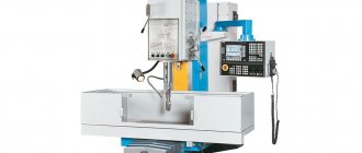
Let's consider the general design of a CNC vertical milling machine, which is the most versatile and in demand for any type. The bed (1) is designed for fastening all components and mechanisms of the machine. The work table (2) can move in the longitudinal (left/right) and transverse (forward/backward) directions along the guides (3).
Machine body.
Structural elements of the machine
Workpieces and various technological devices are fixed on the work table. For this purpose, there are special T-shaped slots on the table. The spindle (4) is designed to clamp the cutting tool and give it rotation. The spindle is mounted on a column (5), which can move in the vertical direction (up/down). The accuracy and quality of processing largely depend on the accuracy of rotation of the spindle, its rigidity and vibration resistance. Thus, the machine in question is 3-axis.
The protective covers (6) are necessary for safety. They protect the machine operator from flying chips and cutting fluid (coolant), which is supplied to the machining area under pressure. The door (7) provides access to the working area of the machine. The drum-type tool magazine (8) contains a set of cutting tools. In this case, taking the required tool and fixing it in the spindle is provided by an automatic tool changer and is carried out according to a specific command from the control program.
ALPHABETICAL INDEX OF EQUIVALENT TERMS IN ENGLISH
| Adaptive control | 5 |
| Block skip | 24 |
| CNC | 6* |
| _______________ *Probably an error in the original. Should read 13. - Note. | |
| Computerized numerical control | 13 |
| Contouring control | 4 |
| Control system | 14 |
| Direct numerical control | 6 |
| D.N.C. | 6 |
| Machine program mirror execution | 29 |
| Manual data input | 27 |
| MDI | 27 |
| Mode of operation, automatic | 23 |
| Mode of operation, manual | 28 |
| Mode of operation, single block | 26 |
| Numerical control | 11, 12 |
| Numerical control of machine | 2 |
| Positioning control | 3 |
| Software | 10 |
(Changed edition, Amendment No. 1).
CNC system design
In order to turn a conventional manual machine into a CNC machine, it is necessary to introduce certain components into its design. It is not enough to simply connect the machine to a computer for it to work according to the program - it is necessary to modernize the mechanical and electronic “stuffing” of the machine. Let's see how the CNC system works on most modern machine tools.
Conventionally, the control system can be divided into three subsystems:
• control subsystem,
• drive subsystem
• feedback subsystem.
Later in this section we will dwell in more detail on each of these subsystems.
Operating principle of CNC
Numerical control requires a special program, which is compiled for the machine once for the production of each type of part, after which the CNC device is able to automatically process the workpiece to the required state.
A metalworking machine with such a system consists of the following parts:
- control subsystem;
- actuating mechanism;
- feedback subsystem.
The design of the system depends on the size of the frame on which all other parts are placed.
Control subsystem
The central part of the entire control system is the control subsystem. On the one hand, it reads the control program and gives commands to various machine units to perform certain operations. On the other hand, it interacts with a person, allowing the machine operator to control the processing process.
The heart of the control subsystem is the controller (processor), which is usually located in the CNC rack housing. The stand itself has a set of buttons and a screen (collectively called the user interface) for entering and displaying the necessary information.
Control systems can be either closed or open, PC compatible. Closed control systems have their own algorithms and work cycles, their own logic. Manufacturers of such systems, as a rule, do not distribute information about their architecture. Most likely, you will not be able to update the software or edit the settings of such a system yourself. Closed-type systems have an important advantage - they usually have high reliability, since all system components have been tested for compatibility.
Recently, more and more open, PC-compatible control systems have begun to appear. Their hardware is almost the same as that of your home personal computer. The advantage of this method is the availability and low cost of electronic components, most of which can be purchased at a regular computer store. However, there is also a drawback. It is currently believed that the reliability of such systems is lower than that of closed control systems.
CNC machine drives
The drive subsystem includes various motors and screw gears for the final execution of commands from the control subsystem - to implement the movement of the machine's executive bodies.
Helical gear
Important components of the drive subsystem are high-precision lead screws. You probably know that on a manually operated machine, the worker moves the work table by rotating a handle connected to a lead screw. A nut is attached to the bottom of the table so that when the screw is turned, the table moves linearly.
The improved lead screw of the CNC machine allows the actuator to move with minimal friction and virtually no backlash. Eliminating backlash is very important for two reasons. Firstly, this is necessary to ensure ultra-precise positioning. Secondly, only if this condition is met is normal down milling possible.
Feedback sensors
The feedback subsystem is mainly designed to provide a control subsystem with information about the real position of the machine's executive body and the speed of the motors. The feedback subsystem can be of open or closed type.
• Open type systems record the presence or absence of a signal from the control subsystem. Unfortunately, they cannot provide information about the actual position of the executive body and the speed of the motors, therefore they are practically not used in modern CNC machines.
• Closed-loop systems use external sensors to check the required parameters.
Feedback circuit on a CNC machine
CNC master what is this position?
A CNC machine foreman or operator is a person who works on this equipment and provides its maintenance. In addition to him, a CNC adjuster is needed who enters and corrects the NC. These specialties can be combined - master adjuster.
Operators have the following job responsibilities: machine maintenance, process control, checking and testing finished products, eliminating minor problems, adjusting components, preparing working tools. It operates on the basis of a job description, which is approved by the enterprise itself. The master can service several machines at the same time. The CNC operator carries out the following work: development of the NC, inputting it into the machine and testing, setting up equipment for specific processes.
Training of operators and adjusters is provided in colleges (technical schools) or in special courses in the specialty “Mechanical Engineering Technology”. In order to become a professional, a worker must acquire the following knowledge: the structure and features of CNC machines, processing technology, the basics of CNC programming, principles of working with computerized systems, signs of malfunctions of CNC equipment, features of various tools and materials. When working, the operator must strictly observe safety precautions.
CNC machines are increasingly being introduced into production. They are capable of providing high precision machining of parts at high speeds. At the same time, the economic feasibility of their use should be taken into account. There are many high-quality models offered on the Russian market, and you need to choose the best option for specific conditions.
- August 30, 2020
- 10681
Sensors used to determine position
Typically, CNC machines use two types of sensors to determine the position and condition of actuators: linear position sensors and rotary position sensors.
A rotating position sensor is mounted on the motor shaft and allows its angular position to be determined. This sensor consists of a light source, an optical sensor (receiver), and a disk with small radial slits (raster). The raster disk is mounted on a shaft; the light source and optical sensor are located on different sides of the disk.
When the disk rotates, the rays pass through its slits and fall on the optical sensor. The optical sensor works like a switch that turns on or off when light rays hit it. This makes it possible to determine the relative or absolute position and direction of rotation of the motor. The received information is sent to the control subsystem.
Rotating position sensor.
All rotating sensors have one significant drawback. Since they are mounted directly on the motor shaft, they cannot directly measure the linear position of the machine's actuator. They provide a calculated position based on lead screw pitch data and are not used in high-precision machine tools to determine linear position. They can be used in the design of a spindle to determine the number of revolutions during rotation and to find its angular position.
Criterias of choice
When choosing a CNC machine for wood, first of all, you need to decide on the area of its use. What challenges does the equipment face? Milling - used for flat, contour or step milling, they can also drill various holes and form grooves, cut or waste threads, and perform other part processing processes. Lathes - process the workpiece during rotation. The results of their actions are less varied. As a rule, these are products of cylindrical, spherical or conical shape. However, using one of the varieties of such equipment - rotary lathes - you can trim ends, form grooves and grooves, etc.
After determining the purpose of the CNC machine, it is necessary to select its operational characteristics:
Engine rotation speed. The generally accepted standard for conventional equipment is 4-8 thousand rpm. For horizontal models of lathes, this figure can increase to 10-20 thousand rpm. The speed of high-speed, most expensive, CNC woodworking machines can reach 40-50 thousand rpm. In addition, you should pay attention to the type of power drive control. Budget versions use step speed control. This can lead to a significant reduction in the accuracy of the part. Therefore, if the product must have minimum tolerances, it is recommended to use servomotors with smooth speed switching.
Work zone. The determining factor is the overall dimensions of the working area, which are closely related to the height of the portal. The dimensions of the workpiece depend on this, which should not extend beyond the working surface of the machine. In addition, the need to install and fix the workpiece should be taken into account.
Processing precision. It is determined by such an indicator as the control criterion of accuracy. Most CNC machines have this indicator in the range of 20-30 control criteria. The most important is accuracy:
- Axis positioning;
- Re-positioning;
- Curvilinear shaped part processed along two axes, etc.
Control method. There are three main types of CNC machine control:
- By connecting to a personal computer via a board. Specialized software is installed on the PC. This includes both controlling the machine’s servo drives and creating a drawing of the part. This method is optimal for individual and small-scale production;
- DSP controller is a microcomputer that is installed directly into the equipment. Its main function is to monitor all operating parameters and control actuators. Receiving commands for processing is carried out by recording special code generated by the design program from a disk, flash drive or other information medium. This option for controlling a CNC machine is used in mass production, when changes to the control program are carried out quite rarely.
- Network control with feedback. At this time it is the most perfect. It allows you not only to record information on processing procedures for several settings at the same time, but also performs a number of other functions: control of the length of the cutting tool, automatic tool change, feedback from servos for particularly precise positioning of the workpiece, etc.
Other criteria by which you should choose a CNC machine for wood include:
- Level of complexity of the processed parts;
- Cost of equipment maintenance;
- The complexity of working with the machine - how much handbrake is required to prepare and start up the equipment;
- Cost of processing one part, etc.
Linear position sensors
They are used in almost all modern CNC machines to accurately determine the absolute or relative position of the actuators. The sensors contain two interconnected units, a raster scale and a read head. The raster scale (1), located along the guides, is a ruler with small rectangular slits (raster). The reading head, moving together with the machine's executive body, consists of illuminators (2), photodetectors (3) and an indicator plate (4). Moreover, the illuminators and the indicator plate are located on one side of the raster scale, and the photodetectors are on the other.
The indicator plate also has two raster sections with a shifted pitch to generate two signals. When the reading head moves along the raster scale, light signals from the illuminators pass through the indicator plate, then through the scale and are recorded by photodetectors. The received signals make it possible to determine the magnitude and direction of movement. The raster scale may contain an additional track of reference marks to set its own reference point.
Linear position sensor.
The CNC system also needs information about the speed, acceleration and deceleration of the machine's actuator. Calculating the amount of acceleration and deceleration is necessary for accurate positioning. The fact is that when the desktop moves to the required position, it slows down the speed of movement in advance so as not to “overshoot” the required coordinate.
How the software works
If the control module is considered to be the brain of the CNC, then the written program is the principle of its operation. Creating a program involves specifying the coordinates of the movement of the working mechanism, the rotation speed and the time for changing the working tools used. In this case, the programmer sets coordinates in three axes. This can be done on an absolute or relative basis. In the first case, when compiling a program, it is necessary to specify a point each time, in the second - the magnitude of the movement and direction. The functional diagram of the device will tell you about the type of software and the connection between the control nodes and the rack.
The main program is executed in one of three ways, depending on the design of the control system. The classification of systems is as follows:
- open-loop or single-flow;
- closed or double-flow;
- adaptive.
The classification method determines which system is needed. In the first case, the program is read in its entirety before execution, after which it is sent to the actuator. The systems are mainly used for simple operations and are absolutely not suitable for machines with servo motors. The open loop program is quite often used on lathes that do not require high precision.
In a closed-loop system, which is a common condition during processing, the program is sent to the actuator as it is being read. In this case, the feedback reports the movement error, and the control system determines which corrective actions need to be sent in real time. Almost all CNC contouring systems are characterized by a closed system.
Adaptive systems are equipped with double feedback. It takes into account not only motion error, but also temperature, contamination, tool wear and other parameters for more efficient machine control. Adaptive systems allow the device to receive full cutting conditions through feedback and create the most accurate corrective action. It has found wide application in metalworking machines, a large number of electromechanical and multifunctional machine tools.
