Metal planing machines are designed for roughing and finishing processing of workpieces of various shapes. Thanks to the ability to replace cutters, you can achieve the desired processing speed, cut various metals, and obtain the required level of productivity. Used in industry, workshops, repair shops.
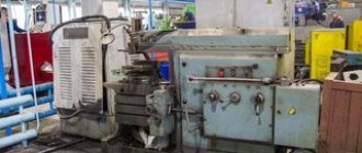
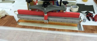
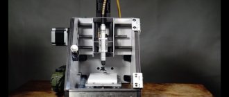
Cross-planing machine (Photo: Instagram / kubanzheldormash)
Construction of wood and metal working planing machines
Planing machine is equipment used for processing flat, shaped and ruled surfaces by chiselling, also called slotting machines.
Such units are used to form grooves, grooves and stamps on metal and wooden parts in individual and small-scale production. This article examines planing machines, we will study their design features, operating principles and varieties, and also learn how to make a simple planing machine with your own hands.
Types of planing units
After analyzing the geometric dimensions of the workpiece, as well as the properties of the metal from which it is made, the surface finishing is carried out on a longitudinal or transverse planing unit.
The fundamental difference between these metal cutting machines is determined by the method of moving the cutter. A table moves on the longitudinal planing unit, with the workpiece fixed on it.
Large blanks are processed in this way. When cross planing is performed, the cutter moves and the workpiece is fixed on the table. This method is used when processing medium-sized parts. In each specific case, cutters of the appropriate configuration are selected.
The same class of metal processing equipment includes slotting, broaching and shaped-planing mechanisms.
Using cutters of various shapes, such machines perform operations of selecting recesses and grooves, turning channels and cutting holes.
One of the features of a metal planer is the number of cutting tools installed.
Some models are designed for simultaneous fastening of several cutters at once.
The following machine models are produced according to these parameters:
- one-sided;
- double sided;
- four-sided.
The more cutting tools installed on a planer-type device, the higher its productivity.
Construction of a longitudinal planing unit
As prescribed by the technical characteristics, longitudinal planing machines are used for processing surfaces on body and asymmetrical parts cast from cast iron or alloys of non-ferrous and ferrous metals.
The dimensions of the workpiece being processed are determined by the technical capabilities of the planing unit. The initial workpiece to be processed is placed on the table.
The table is capable of performing reciprocating movements. In this case, the cutter fixed in the support remains motionless.
When the table is idling, the support moves to the side, allowing the table to move freely to its starting point.
This complex movement allows you to process large workpieces with several cutters at once.
A longitudinal planing machine for the production of metal products is composed of a frame, a table, supports, a cross member, electrical equipment, a lubrication system and other components.
Each model has its own length and width of the working surface of the table. A common element for all models is the control panel.
When processing parts with complex geometric dimensions, several cutting tools can be installed on the support. This technique reduces the time for processing the product.
Design of a cross-planing unit
A cross-type metal planing machine is installed in production lines where small and medium-sized parts are processed.
The unit is used for planing horizontal, vertical and inclined surfaces.
As in any metalworking machine, the main elements of the cross-planing unit are the bed and the base.
All components and devices that are designed to ensure fastening and movement of the corresponding elements are attached to this support. The part is fixed on the table at the specified coordinates.
The support, with the cutter fixed in it, is given movement within certain limits.
In the process of metal processing, parts assemblies and structural elements perform complex movements, the purpose of which is to carry out a given program.
The planing unit for metal of the cross type can operate under manual control or according to a given program.
The main one is the reciprocating movement of the slider on which the cutting tool is attached.
Auxiliary is the movement of the table on which the workpiece is fixed. The speed of movement of the slider is controlled using a special gearbox, like in a car.
Before processing any part, all mechanical components of the unit must be lubricated with machine oil.
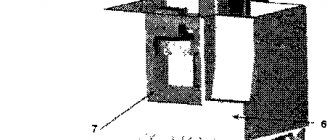
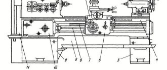
Arrangement of the components of the cross-planing machine 7e35
List of components of the cross-planing machine 7E35
- Bed - 7E3510000
- Caliper - 7E3531000
- Automatic caliper feed mechanism* - 7E3533000
- Slider - 7E3530000
- Electrical equipment - 7E3580000
- Gearbox - 7E3520000
- Gearbox shift mechanism - 7E3521000
- Centralized lubrication - 7E3570000
- Feed box - 7E3550000
- Rocker mechanism - 7E3540000
- Cross member* - 7E3560000
- Universal table** – 7E3561000
12. Table*** - 7E3562000
*On special order.
**Only for machines with a universal rotary table.
***Only for machines with a rectangular fixed table.
Types of cutters for planing equipment
Cutters used for processing parts on a metal planing machine are divided according to a number of characteristics:
- In the direction of delivery; (left and right)
- According to the shape of the head; (straight, bent, with a retracted head)
- By manufacturing method; (solid and composite)
- By type of work performed (through roughing and finishing, shaped, cutting, grooving, etc.)
The process of planing metal occurs only with a working cutter, or on tables with a firmly fixed workpiece.
At the moment when the cutting tool is tightly fixed in the folding holder, its process of wear and exhaustion will take much longer, since during the return stroke it begins to fold back and move freely over the entire surface.
Main criteria for choosing a cutter model:
- type of equipment - for longitudinal or transverse operations;
- cutting edge material. Affects the speed and accuracy of work;
- cutter shape. Depending on this parameter, grooves, holes or grooves will be formed on the surface of the part.
There are several types of operations carried out on a longitudinal planing machine. They can be pass-through, finishing, shaped, trimmed or cut-off. To increase the service life of cutters, it is recommended to use equipment with a folding locking head. After initial processing, the cutter returns to its original position. During the return stroke, it should not come into contact with the surface of the workpiece.
The most common are longitudinal planing machines. They are characterized by relatively small dimensions and ease of operation. Particular attention should be paid to the quality of cutting tools. To ensure an uninterrupted technological process, it is necessary to have a small supply.
Device
To perform the functions assigned to it efficiently, planing machines must include the following components:
- bed;
- a support with one or more tool holders;
- frame (on large machines the frame has a portal configuration, on smaller ones it is in the form of a console);
- mechanism for moving the table and/or support;
- work table with T-shaped slots for precise positioning of the product;
- electric motor;
- pumping station for supplying lubricating and cooling media to the planing zone;
- a cross member that connects the elements of the frame and gives it the necessary rigidity;
- control unit.
For working movements of the cutter in longitudinal planing machines, a crank drive is used. Numerous options for setting it up allow you to perform operations with metal on vertical, horizontal and even inclined planes.
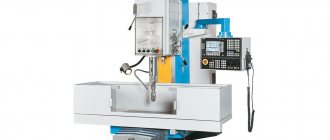
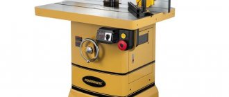
Chinese machine model
The speed of movement of the moving parts is changed by a gearbox, which contains a set of several gear pairs. By including (manually or according to a program) a certain pair in the work, a new speed of movement of the workpiece or tool is obtained. The choice depends on the mechanical characteristics of the metal being processed. For less ductile materials, power cutting is used with increased feed rates, and ductile workpieces are planed at reduced speeds to prevent chips from sticking to the cutter, reduce friction losses and reduce thermal deformation of the workpiece.
Scope of application
This equipment is not highly productive; due to the idle reverse motion and the inadmissibility of high cutting speeds due to inertia, the dimensions of the workpieces processed are limited; longitudinal planing machines are practically not used for mass production of metal products. But they are the best when it is necessary to form complex grooves and profiles using cutters or the use of rotating cutters is inadmissible.
A wide variety of working tools are fixed in the support assembly of such machines, including passing, trimming, slotting and shaped cutters, which allow roughing and finishing planing operations to be performed with their inherent accuracy (average deviations do not exceed 0.03 mm per 300 mm length of the metal workpiece).
In particular, the cross-planing machine is successfully used:
- When planing horizontal planes with the help of universal cutters, vertical ones with scoring cutters complete with stops.
- Processing of parallel planes with division of the process into two stages and sequential execution of work
- When planing inclined planes by installing the support at an angle and ensuring its feed in a parallel direction. The maximum effect is achieved when it is necessary to process a narrow strip (10-30 mm); with such parameters, all the advantages of fixing a wide and non-rotating cutter are manifested.
- When making grooves and grooves, including keyways.
- When planing chamfers using concave, convex and similar cutters. In the manufacture of gears, couplings and cams (subject to the use of additional specialized and dividing devices).
Inferior to milling and turning models in productivity and price, this equipment wins in the low cost of the attached working tool and in the ease of sharpening it. For this reason, such machines are recommended to be purchased if you need to remove scale or form precise grooves and grooves in flat and shaped workpieces in a minimum number of passes.
Types of devices
A planing device for a metal surface can be of two types at once: longitudinal planing and transverse planing. The principle of processing such parts on equipment will differ significantly .
Longitudinal planing machines are designed to work with a fairly short surface. That is why in them the movement occurs on the table to which the part being processed is attached. While the cutter itself will be installed by the cutting head of the support, and also relative to the bed, the machine will not carry out any movement.
In a cross-planing machine, the work occurs in a completely different way: the cutter produces movement, and the semi-finished product installed on the table remains stationary.
Planing types of machines are significantly inferior to milling machines in their functioning, since they have an idle stage, while the workpiece or the same cutter moves to a new position. In this case, the drive will not be very energy-intensive , since the process of rotational movement of the working device (as in a milling machine) will require significantly greater costs from the drive electric motor.
Overview of the machine range
The main developer and manufacturer of planing equipment of this group is the Orenburg SZ; many domestic companies offer to purchase ready-made, repaired or modernized devices, Pressmash, Stanochny Mir); among used machines, the products of the Gomel SZ have good reviews. The models have a generally similar design, the differences are manifested in the dimensions, power and parameters of the workpiece being processed. The main indicators of the most common of them are presented below:
7305T
The basic model of a cross-planing machine, supplied without a slotting head at a price of 680,000 rubles and used for processing flat and shaped metal products in all planes, including inclined.
| Characteristic | 7305T | 7307GT |
| Slider stroke, mm: | ||
| largest for planing | 500 | 710 |
| largest for chiselling | 200 | 250 |
| Dimensions of the upper working surface of the table, mm | 500x400 | 710x450 |
| Slider stroke frequency, stroke/min | 13,2-150 | 10,6-118 |
| Table feed, mm/double stroke: | ||
| Horizontal | 0,2-5,0 | |
| Vertical | 0,04-1,0 | |
| Main drive power, kW | 5,5 | |
| Weight 7305T machine (without accessories) kg, max | 1980 | 2770 |
| Overall dimensions of the machine, mm | 2380x1085x1560 | 2790x1375x1665 |
| Overall dimensions of packaging, mm | 2400x1306x1620 | 2800x1400x1740 |
This equipment is distinguished by its increased rigidity of the frame and guide and has a good power resource (up to 5500 W), facilitating the precise performance of finishing, roughing and fine planing.
The machine is equipped with a 500×400 rotary table with 25 feeds and three T-shaped slots for gripping workpieces with a slide stroke of up to 510 mm and an outreach of up to 560; the maximum distance between the horizontal plane and the guides is 40 cm.
7307TD
Expanded modification 7305T with a slotting head and a slider stroke increased to 710. By analogy with the previous one, this cross-planing machine is recommended to be purchased when processing flat and shaped workpieces made of hard materials (the permissible cutting force reaches 19.6 kN); with equal power and table movement speed, it wins in functionality and increased working space.
This affects the price; in new condition, this model can be purchased from 800,000 rubles and above. At the same time, its optimal scope of application is enterprises with single and small-scale production conditions.
7B35
Planing equipment for processing with a cutter workpieces with a length of up to 500 mm inclusive and forming grooves and grooves in them with different shapes and depths within the cross-section of the working tool 20×32 mm. The model was developed for installation in repair, mechanical and tool shops of mechanical and instrument manufacturing enterprises with relatively small production volumes (single and small-scale production of metal parts).
In the basic version, 7B35 has a fixed table with 20 feeds and manual, mechanical and root movement; models with universal rotary structures are made to order. The machine is equipped with a centralized lubrication unit and a chip collector; the estimated costs for purchasing it in basic configuration and in good condition are 600,000 rubles.
7M36 and 7M37
The cross-planing machine of the Gomel SZ is the base for models with a universal rotary table and copying devices, used for processing their metal surfaces with a slide length of up to 700 mm inclusive. At the moment, the model has been discontinued from main production and replaced with improved slotting analogues, but thanks to the reliability of the components and hydraulic drive, it is still used in machine shops of machine-building enterprises and is sold in used condition at a price of 140,000 rubles and above.
The machine has 2 electric motors (the main one ensures the start of all components, the auxiliary one ensures rapid movement of the worktable with dimensions of 450×700 and 560×1000 mm, respectively), the lubrication of its frame and slider guides is carried out automatically, the same applies to the feed of the support and cutter.
General classification
Metal processing equipment is divided into 11 groups:
- Metal lathes. External and internal surfaces of rotation are processed. They have one thing in common: rotation of the part around its axis.
- Drilling machines. This group also includes boring machines. Used for passing through and blind holes. They are united by the rotation of the working tool and its simultaneous feeding. In horizontal boring mechanisms, feeding occurs due to the movement of the work table with the fixed part.
- Grinding machines. All such machines use an abrasive grinding wheel as a working tool.
- Polishing and finishing machines. A common feature is the use of abrasive wheels and polishing pastes.
- Gear processing machines. Designed for cutting gear and wheel teeth. This also includes grinding machines.
- Milling machines. In this group, the working tool is a multi-edge milling cutter.
- Planing machines. For these machines, the working stroke is a reciprocating movement of the cutter or workpiece.
- Slitting machines. They are used for dividing into parts by cutting a metal profile (angle, channel, rod, etc.).
- Broaching machines. The working tools are special multi-blade broaches.
- Thread processing machines. This includes equipment specifically designed for thread cutting. This group does not include lathes.
- Auxiliary and miscellaneous machines. They belong to a separate group and perform various auxiliary operations.
Classification by type
Equipment of the same type may have different layouts. A milling machine can be called horizontal or vertical - based on the location of the spindle axis. Kinematic schemes for transmitting movements, control systems, and cutting accuracy parameters differ.
Machines of the same type with a similar layout and kinematics, but having different sizes, will be combined into a size range. For example, gear hobbing machines are divided into 12 standard sizes depending on the parts being manufactured (from 80 mm to 12,000 mm). Each standard size of a machine designed for a specific processing of parts is called a model. Each model has its own designations: a combination of numbers and letters indicating the machine group, the maximum dimensions of the workpiece, the difference from the base model.
Classification by versatility
Processing mechanisms of the same group can perform different tasks:
- Universal ones process a wide range of products. The dimensions of the blanks may vary. Capable of performing any technological operations provided for this group.
- Specialized ones produce parts of the same type (body parts, shafts, similar in shape, but different in size).
- Special ones perform operations on one part of various sizes.
Classification by degree of accuracy
The degree of processing accuracy on a given machine is indicated by the letter included in its designation:
- N - normal accuracy;
- P - increased accuracy;
- B - high accuracy;
- A - particularly high accuracy;
- C - especially precise master machines.
Example: 16K20P - a lathe with increased accuracy.
Classification by degree of automation
Processing equipment is divided into automatic and semi-automatic. The working cycle of the machines is completely autonomous. In semi-automatic machines, loading of workpieces and removal of processed products is carried out by the operator. It also launches the next processing cycle.
Integrated automation of large-scale production of metal products involves the installation of automatic production lines from separate automatic machines. Products are produced in small batches using flexible production modules.
Machines that produce products under CNC control are designated by the letter C (cycle) or F. The numbers indicate a feature of the control system:
- F1 - digital display and preliminary selection of coordinates;
- F2 - positional control system;
- F3 - loop control system;
- F4 is a universal control system.
For example, the range of CNC metal lathes from the StankoMashKompleks company can be viewed at the link provided.
Classification by weight
Depending on the mass of manufactured parts, machines are divided into:
- lightweight, weighing up to 1000 kg;
- medium, weighing up to 10,000 kg;
- heavy, weighing from 10,000 kg, which, in turn, are divided into large (16,000-30,000 kg) and actually heavy (up to 100,000 kg);
- especially heavy - over 100,000 kg.
Machine numbering
Identification of any metalworking machine is based on assigning an alphanumeric code to it.
The numbers indicate which group the machine belongs to (lathe, milling, etc.), indicate the type and nominal size of the equipment. By deciphering the numbering, you can find out the height of the centers, the maximum dimensions of the workpieces or the drilling diameters of the workpieces.
Machining machines of the same size but with different characteristics are identified by the letter entered between the first and second digit. For example, lathes models 162 and 1K62 differ in maximum rotation speed. The first one has 600 rpm, the second one has 2000 rpm.
The difference between modifications of machines of the same model can be determined by the letter at the end of the number. If the numbering of the basic model of a horizontal milling machine is 6N82, then the simplified modification of this machine is 6N82G.
Numbering occurs when the fourth digit identifies an improved version of a machine of the same standard size. Thus, the horizontal boring machine model 262 has a modern modification, designated 2620.
Assigning alphanumeric indices to metalworking machines makes it easy to find the corresponding equipment in special catalogs. Indexing also makes it possible to quickly find the necessary spare parts.
Schemes of metal processing by planing
The last two digits of the marking indicate the main technological parameter of the equipment. As a rule, this is the largest dimension of the processed product in decimeters. For example, brand 7310 will indicate that this unit is a cross-planing unit and is intended for processing metal with a maximum plane length of up to 1000 mm. The letter in the designation (for example, 7A110) indicates a modification of the base model (for example, the presence of a hydraulic drive, an additional clamping unit, etc.). The presence of the letter F in the designation indicates that this equipment is equipped with a CNC system.
Planing equipment should be used in technological campaigns for the processing and production of various types of parts. The initial types of workpieces undergo a multi-stage processing process on machines of a certain type. The equipment produced at a machine-building enterprise uses parts of different configurations and dimensions.
Operating principle of a deep vibrator
Uncured concrete mixture has a very thick consistency. Due to the fact that the material is dense and heavy, and also has low fluidity, air bubbles from the lower layers cannot rise to the top.
Vibration makes wet concrete more flexible, temporarily giving it the properties of a liquid. Thanks to this, air can leave it freely, and the mixture itself is further compacted.
How do deep vibrators work? The equipment consists of several structural elements:
- Drive unit
. An electric, motor or pneumatic motor creates vibrations, which are then transmitted to the concrete mixture. - Balancer
. This structural element converts the rotation of the motor into vibration of the desired frequency. - Transmission shaft. A flexible cable transmits vibrations to the tip, which is immersed directly in the solution. The depth to which the vibrating mace can be lowered depends on its length.
- Vibrating tip. Through this node the material is affected. They come in different types - bayonets, shovels, rods. The shape of the tip determines the volume of concrete processed, as well as the time required to compact each section.
The principle of operation of construction equipment is simple: motor rotations are converted using a balancer into vibrations, which are then transmitted through a flexible shaft to a tip, which is immersed in the concrete mixture for the time required to process a section of the concrete block.
A large area (screed, foundation or slab) is processed sequentially - from section to section. The processing time depends on the thickness of the layer, the grade of concrete and the power of the vibrator.