The jointer's job is to make the workpiece smooth and flat. To do this, you need to know how the jointer works, how to set it up correctly and how to use it, and also know the rules for keeping the tool in working condition. Planer, a device designed to level the surface of a workpiece with sharp blades. The device has two separate tables: a receiving table and a feeding table. It is probably clear that the feeder is the table where the workpiece material moves to the cutting part of the tool - the cutting head, and the receiving table is the table where the material is placed after passing the cutting head.
Knife
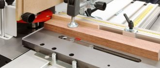
Next you should check the knives. The height should be equal to the height of the receiving table. Incorrect knife adjustment will result in roughness or chipping of the workpiece. The pictures show how a ruler is used to check the placement of knives on the same level. To do this, use a wrench, loosen the knife bar, straighten and tighten the nuts. Check the height of the knives. The figure shows the final result of the adjustment. By rotating the cutting head, make sure that each of the knives makes light contact at the top point.
Planing depth
After adjusting the height of the knives, you need to go to the planing depth settings, which means how deep the jointer will plan the wood. The planing depth is set by moving the feed table up or down. The next step is to check the jointer stop.
Emphasis
The stop must be adjusted at an angle of 90° in relation to the feed and take-out tables. This is a simple procedure. Adjustment of the stop is done using a square and the tables must be clean.
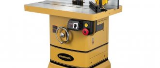
Wood planer for home workshop
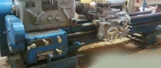
A jointer is used to process wood mechanically using a cutting tool.
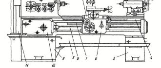
It produces planing in a straight direction of wooden parts along the surface or edges. Based on the number of cutting mechanisms, a distinction is made between double-sided and single-sided machines; the first version of the equipment is designed for jointing two adjacent surfaces simultaneously. The supply of the workpiece to work is organized mechanically or manually. For mechanical movement of parts, an automatic feeding device attached to the machine or a conveyor built into the unit is used. to remove dust and chips.
Joining workpieces
Fiber direction
To connect two workpieces, the workpieces must be parallel and square. There are several tips to get a good result. Determining the direction of grain in wood, i.e. You need to feed the workpiece to the knives with the narrow part of the wedge. See the photo in the figure with illustrations of the direction of the fibers.
Cutting depth
The cutting depth is set to no more than 1.7 mm. This promotes smooth processing of the material and maintains the durability of the knives. An exception can only be when planing uneven surfaces.
Edge jointing
The workpiece must be held facing the stop. You need to start by applying pressure to the leading edge of the wood as you move towards the cutting part. The pressure then moves to the middle and to the edges. Those. the workpiece must have constant contact with the stop and the receiving table. The last pass should be slow to obtain a smooth surface. When splicing workpieces, it is necessary to adjust the edges and make sure that there are no gaps, and also take into account the direction of the fibers in order to hide the joint. The process of selecting fiber direction is not easy.
Post Views: 3,659
Making a machine yourself
To begin with, determine the number of functions of the future unit . It could be:
- just a planer with one planing operation;
- a combination of a jointer and a circular saw, which doubles the usefulness of the equipment;
- they add grinding, sharpening and drilling functions, but for your own workshop, making a complex set of equipment with your own hands is a difficult task.
Often, craftsmen independently make a jointing machine with a sawing function, while the torque is transmitted from one electric motor, which includes structural elements:
- The bed can support the weight of the work plane and installed electrical and mechanical equipment. In a workshop, a channel with a shelf thickness of at least 10 mm is used to make the frame. The structure can be made stationary (welded) or provided with bolted components for disassembly if necessary. The first option is more reliable and is used if a portable machine is not needed. Sometimes the desktop itself acts as a bed.
- Working tools include knives and saws; the work of processing and sawing workpieces depends on their quality. Reliable and strong steel is used for cutting blades; the saw teeth must be equipped with Pobedit tips.
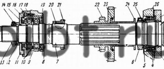
- Without a rotor, to which all the tools are attached, not a single woodworking machine will function, so attention is paid to its selection. Most often it is made by a specialist turner according to the drawings offered to him.
- The design of a jointing unit with a sawing function provides three working surfaces - one serves as a table for the circular saw, the other two feed and receive the workpiece during the jointing process. Multilayer plywood, the thickness of which is at least 5 mm, or sheet metal, is used as a covering. Typically, the feed surface is made 2-3 mm below the receiving side to facilitate the process and reduce vibration load.
Electric drive of the machine
The operation of the jointer and saw is based on rotational functions, which is why the drive is called the heart of the unit.
A three-phase motor is suitable as an electric motor; sometimes the wiring is re-equipped for this in the workshop. Three-phase units with a voltage of 380 V are characterized by high power and suitable torque. The minimum permissible engine power is 3 kW, the maximum is not limited. The transmission of rotation from the engine to the shaft is carried out by means of a belt drive. V-shaped double-ribbed belts work well in such conditions; they are reliable in operation. The electric motor is mounted using a console inside the frame structure of the bed; the installation method helps to regulate the tension of the belts. Another way is to mount it using a slide - this still allows for adjustment, but the engine itself is more firmly fixed.
To accelerate the rotation of the shaft, two pulleys of different diameters are used. The larger one is placed on the electric motor, the smaller pulley is placed on the shaft. To supply electrical power, choose a cable with four cores; such wiring reduces the danger of operation.
Wood and metal processing
The quality of parts processing is significantly influenced by the geometric accuracy of the machine, the correctness of its adjustment and settings.
Woodworking machines, according to the accuracy of the work performed on them, are divided into four classes: special precision (O), manufactured with strict requirements for the quality of assembly units and parts and ensuring processing accuracy of 10 ... 12 qualifications (machines for the manufacture of high-precision drawing instruments, pianos and etc.); increased accuracy (P), ensuring during normal operation processing accuracy according to the 11th...12th qualifications (milling, four-sided, moulding, etc.); medium precision (C), providing processing according to the 13th...15th qualifications (lathes, drilling machines, circular saws for finishing, etc.); normal accuracy (N), ensuring processing accuracy according to 14...18 qualifications (band saws, circular saws, etc.).
There are the following main causes of errors during mechanical processing of wood.
Geometric inaccuracy of the machine and its wear. Machine parts are manufactured with certain errors. In the process of assembling machine components, these errors are added up and thus general errors appear, which characterize the accuracy of the location of the operating surfaces of the machine. In addition, wear of parts during operation of the machine reduces its initial accuracy.
Inaccuracy of the cutting tool. The processing accuracy is affected by the distortion of the shape of the cutting edge of the cutter during sharpening, the error when installing and securing the cutting tool, as well as its runout.
Fixture inaccuracy. The clamping and installation elements of the fixture have errors even with the most careful manufacturing. When installing a workpiece into a fixture, alignment errors occur. Elastic deformations occur in the fixture elements under the action of clamping and cutting forces, which also reduce the accuracy of the part.
Insufficient rigidity of the machine-fixture-tool-part system (AIDS). The rigidity of the AIDS system is its ability to provide the necessary processing accuracy under the loads that arise during the operation of the machine.
When processing a batch of workpieces, the cutting forces change depending on the amount of processing allowance, the degree of dullness of the tool and the mechanical properties of the wood. This change causes elastic deformation of the AIDS technological system. The resulting deformations disrupt the location of the machine's mounting surfaces, which leads to a decrease in processing accuracy.
Errors when setting up the machine. Such errors arise due to incorrect readings on a scale or dial, measurement error of test parts, and inaccuracy of the control and measuring instrument. Errors arising due to these reasons form the resulting machining error.
The task of the machine operator is to promptly identify the causes of processing errors and eliminate them through proper setup and adjustment of the machine.
Setting up a machine is a set of labor techniques performed with the aim of regulating and coordinating the interaction of all elements of the machine, establishing processing modes, test run and control of machined parts.
Dimensional adjustment of a machine is a set of labor actions to ensure the required accuracy of the location of the cutting tool relative to the installation elements of the machine (tables, guides, stops).
Upon completion of the commissioning and tuning work, the machine must ensure that the specified functions are performed with the required productivity and quality of processing.
Depending on the type of tools used, the following types of settings are distinguished.
Static adjustment using measuring devices built into the machine (manually driven adjustment mechanisms equipped with built-in devices in the form of scale dials, verniers or digital reading devices) consists in the fact that the machine operator moves the working element to the required adjustment size and at the same time visually controls the amount of movement along reading device.
Static adjustment of the machine according to the standard (template) consists of adjusting the position of the tool until its blades touch the working surface of the template. The template is made of light metal, wood-laminated plastic or hardwood. The permissible deviation for the setting size must be less than the permissible deviation for the size of the part to be processed. Often a part previously made on a machine is used as a standard. It is advisable to use standards when setting up multi-spindle machines, as well as in cases where several adjustment dimensions or relative positions of cutting tools processing a part of complex shape are taken into account simultaneously. Setting up machines according to a standard in some cases does not provide the required accuracy and is not final. After processing a certain number of parts, additional adjustments and adjustments of the machine are necessary.
Features of operation
Woodworking equipment, like any other, requires attentiveness and caution, compliance with certain operating rules:
- Regular inspections and preventive repairs are carried out, blades are sharpened, saw blades are changed;
- Preventative injection of bearings, control check of engine operation, inspection of belts, tightening of sagging, cleaning of contacts and other work are carried out;
- The engine is provided with a protective casing; operation without it is prohibited;
- The machine operator's workplace must be well lit, the floor covering is made of rough materials that prevent slipping;
- an assistant is invited to work with long and large parts, this will protect the master from injuries and machine breakdowns;
- keep the workplace clean, promptly remove chips from the floor and inside the unit (after turning off the electricity), remove unnecessary objects from the workspace around the machine.
Operating rules are shown in the video.
The use of electrical wood processing is effective compared to manual planing and jointing. To obtain high-quality workpieces without injuries and accidents, follow safety precautions and equipment operating rules.