Setting up a lathe for thread cutting
When cutting threads, the equations of kinematic chains are compiled based on the condition that during one revolution of the spindle the tool must move in the feed direction by the pitch Pp of the thread being cut.
Let us write the kinematic balance equation for cutting metric threads with a minimum pitch:
When cutting a modular thread with a minimum pitch, instead of replacement wheels z = 40-73, 73-64, wheels z = 60-73, 86-36 should be substituted into this equation. The kinematic balance equation for cutting inch threads in general form:
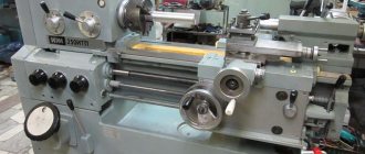
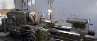
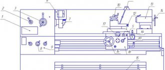
Setting up a modern universal screw-cutting lathe 1K620
for thread cutting comes down to setting up the drives of the main movement and the feed movement.
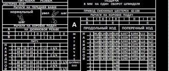
Setting the feed box to the pitch of the thread being cut is in most cases carried out using a table mounted on the machine, or according to a passport.
The feed box control handles are set to the position indicated in the table, and the reverse of the lead screw is set to the position corresponding to cutting a right-handed or left-handed thread, and, if necessary, turn on a link for increasing the thread pitch.
Rotation from the feed box is imparted to the lead screw, and the longitudinal movement of the caliper with the threaded cutter is activated when the split nut is closed.
When cutting high-precision threads or with a non-standard pitch, adjusting the longitudinal feed chain requires preliminary calculations, sometimes quite complex (for example, when adjusting a screw-cutting chain not with a feed box, but with a guitar of interchangeable wheels). Modern universal lathes provide the ability to completely disable the feed box; The driven shaft of the guitar is connected directly to the lead screw of the machine. In these cases, it is necessary to select replacement wheels from those included with the machine or make additional ones. The number of teeth on replacement wheels can be selected in two ways.
In the first method, the feed box levers are placed in a position in which the cut pitch is equal to the pitch of the machine lead screw. Thus, the gear ratio is equal to the pitch of the threaded screw divided by the pitch of the lead screw. In cases where the numerator or denominator of the gear ratio of a simple fraction will have factors that are inconvenient for converting them into the number of teeth of replacement gears, the calculation should be carried out using tables of gear ratios.
In the second method, the selection of replacement wheels is carried out according to one of the gear ratios of the replacement wheels available (even from other machines), or according to the gear ratio of the feed box.
If it is necessary to produce a thread with small pitch tolerances, and the machine lead screw has a manufacturing error, then the selection is performed using approximate methods.
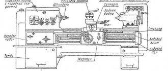
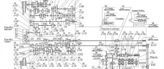
Kinematic diagram of a screw-cutting lathe 16k20
Kinematic diagram of a screw-cutting lathe 16k20
Main parameters and areas of application
The parameters that determine the characteristics of the pitch thread include:
- coil profile (its geometric shape and angle of inclination);
- thread pitch (distance between points of the same name);
- dimensions of the three main circles (middle, inner and outer);
- thread progress and cutting.
Each of the parameters has its own notation system. A distinctive feature is the step unit. For example, a modular thread has a designation called module. In a pitch system, it is measured in pitches. For example, a step equal to two pitches corresponds to 6.28 decimeters. Pitch is equal to the ratio of the number of teeth of the wheel being cut to its diameter. To systematize existing sizes and convert them into the most understandable systems, a special table is used.
Both types of thread (modular and pitch) have several types of thread profiles:
- in the shape of an Archimedean spiral;
- involute (a second-order curve, each point of which is tangent to a given circle);
- trapezoidal shape.
Thread cutting on a screw-cutting lathe 16K20
The main movement chain (see kinematic diagram) sets the rotational movement of the machine spindle (shaft VI). From the electric motor M (N = 10 kW, n = 1460 rpm, through a V-belt transmission and gearbox, the spindle can receive 24 different rotation speeds in the range 12.5 ... 1600 min -1 (Table 4.1) and at the same time have direct and reverse rotation.
The screw-cutting chain (longitudinal feed chain) coordinates the rotational movement of the workpiece and the translational movement of the thread cutter along the axis of the workpiece so that during one revolution of the workpiece the cutter moves one step (if the thread is single-start) or one stroke (if the thread is multi-start). The initial link of this chain is the machine spindle, then the movement goes through the feed box. The final link is the machine lead screw with a pitch of Px = 12 mm (see Fig. 4.2). Adjustment to the pitch of the thread being cut is carried out using a set of replaceable gears (K, L, M, N) and a feed box (see Fig. 4.6).
The equation for the kinematic balance of a screw-cutting chain has the form
1 rev/shp · (60/60) · (30/25) · (25/45) · (K/L) · (M/N) iк.п Px = Pн
Where:
ik.p – gear ratio of the feed box.
This equation is used to derive calculation formulas for selecting replacement guitar wheels for threads with a pitch Pn equal to or different from the tabulated Pt.
The feed box (see kinematic diagram) has two main kinematic chains. One chain is used for cutting metric and modular threads, as well as longitudinal and transverse mechanical feed. In this case, clutches M2 and M6 are turned off, and clutches M3, M4 and M5 are turned on:
Another chain is designed for cutting inch and pitch threads. In this case, movement is transmitted to the lead screw when clutches M2, M3, M4 and M6 are turned off and clutch M5 is turned on:
When cutting metric and inch threads, install a standard set of replacement guitar gears:
(K/L)·(L/N) = (40/86)·(86/64)
and when cutting modular threads:
(K/L)·(M/N) = (60/73)·(86/36)
When cutting threads with a pitch Px different from the tabulated Pt, replaceable guitar gears are selected by calculation. The selection of wheels is carried out according to a pre-selected value of the feedbox gear ratio (let us take the feedbox gear ratio equal to one).
Setting up a 16k20 machine for thread cutting
Setting up the machine for thread cutting is carried out in the following order:
1) based on the given cutting speed, we calculate the spindle rotation speed:
n = ν 1000 60/d rpm,
Where:
ν – specified cutting speed, m/s;
d – workpiece diameter, mm.
The resulting value n is adjusted according to the Table of threads and feeds;
2) according to table. 4.2 we determine whether the given pitch of the thread being cut corresponds to the table value;
3) if the given pitch corresponds to the table one, then the thread can be cut without special settings, using the instructions on the position of the feed box handles located on the machine;
4) if the given pitch does not correspond to the tabulated one (see Table 4.2), then for thread cutting it is necessary to perform a special adjustment, using the calculation formula to determine the gear ratio of the replacement wheel guitar.
For example, for a metric thread the calculation formula is:
(K/L)·(M/N) = (5/8)·(Pn/Pt)
Where
Pn – pitch of the thread being cut,
Pt – table value of the pitch closest to the pitch of the thread being cut.
Based on the calculation results, replacement wheels are selected from the following set:
36, 40, 44, 45, 46, 48, 50, 52, 54, 56, 57, 60, 64, 65, 66, 70, 72, 73, 75, 80, 86, 90, 127
(all gears have the same module m = 2mm).
Thread cutting, depending on the pitch Pn, is carried out in several passes.
There are even and odd threads:
An even thread is a thread in which the ratio of the pitch (stroke) to the pitch of the machine lead screw (or vice versa) is an integer.
Odd – the one for which the indicated ratio is fractional.
This division determines the machine setting techniques that are used when cutting threads.
When cutting even threads, at the end of the pass, the cutter is moved to its original position manually or mechanically (accelerated) with the split nut of the lead screw open. The kinematic connection between the spindle and the lead screw makes it possible to engage the split nut of the lead screw at any position of the cutter relative to the thread and guarantees that it fits accurately into the thread groove being cut.
When cutting odd threads, after each working pass, the cutter is moved away from the workpiece in the transverse direction, the caliper is switched to reverse and, without opening the split nut, the cutter is moved back to its original position. The cutter is then set to the specified depth of cut and the next pass is made.
Let's look at setting up a machine using an example.
Example.
It is required to cut a metric thread with a pitch of Pн = 5.5 mm.
Outer diameter of the workpiece D = 40 mm. The workpiece material is structural steel. The cutter material is high-speed steel. Cutting speed v = 0.33 m/s.
Solution:
1) based on the given cutting speed, we calculate the spindle rotation speed:
nshp = 1000 60 v / (πD) = 1000 60 0.33 /( 3.14 40) = 159 rpm
The resulting value nshp = 159 rpm is corrected according to the table. 4.1. To set up the machine, we take the table value closest to the calculated value - nshp = 160 min–1;
2) according to table. 4.2 we determine the correspondence of the given pitch Pn of the cut thread to the table value Pt;
3) the specified thread pitch Pn does not correspond to the tabulated Pt.
We carry out a special adjustment using the calculation formula to determine the gear ratio of the guitar of replacement wheels for metric threads.
The Pt values closest to the pitch of the thread being cut are 5 or 6 mm. We select Pt = 6 mm and substitute this value into the calculation formula:
The number of teeth of the replacement wheels is selected from the set of replacement wheels:
K=50, L=80, M=66, N=72
We check the adhesion condition of the selected replacement gears (Fig. 4.7)
For design reasons, guitar gears should have the following number of teeth:
K ≤ 88, N ≤ 73; K + L + M ≥ 260
4) install the replacement wheels selected by calculation on the machine. In this case, we adjust the feed box using the handles to a step Pt = 6 mm.
Slicing technology
Cutting modular and pitch shapes is carried out on metal-cutting machines in the following ways:
- cutter on screw-cutting lathes;
- modular cutter on milling machines;
- special finger cutters.
The first method of pitch cutting provides high accuracy, but has low productivity. With its help, pitch threads are cut on worm shafts that require high precision motion transmission. This method is used in enterprises with individual or small-scale production.
The second and third methods are considered more productive. The cutter is installed so that its axis of rotation intersects the longitudinal axis of the workpiece shaft strictly at an angle of 90 degrees. To ensure high quality threads (modular or pitch), several passes are made. The most convenient for cutting pitch joints are machines equipped with twin-shaft feed mechanisms or so-called Norton gearboxes.
Before cutting, the machine is set up based on data from special tables that indicate the pitch values. With their help, the required set of gears is installed on a screw-cut guitar with specified gear ratios.
Finger cutters are used for cutting pitch joints on products with large dimensions. To implement pitch cutting, special milling heads are installed that have an individual cutter drive. The first pass is carried out with a slotted finger cutter of a straight-through profile, with a profile angle of 35 degrees.
Techniques for cutting threads with cutters
After setting up the machine, securing the workpiece, installing and securing the cutter, turn on the machine and begin cutting the thread, slightly deepening the cutter into the metal. A screw mark is obtained on the surface of the part, the pitch of which is checked with a ruler, caliper or thread gauge. Before starting the next pass, the cutter is deepened along the limb by the required amount.
You can cut a triangular thread profile with cutters in the following ways.
First way.
The cutter is installed perpendicular to the axis of the part (Fig. 224, a), using a template, as shown in Fig. 219.
Before each new pass, the cutter is removed from the groove by moving the transverse slide towards itself. Then the machine is reversed, returning the longitudinal slide of the support to its initial position. Upon return of the longitudinal slide, the cutter is given transverse movement (Fig. 224, b). The counting is carried out along the dial of the cross-feed screw. All these techniques are repeated in this way until the thread is cut to the full depth of the profile.
As can be seen from Fig. 224, b, the thread in this case is cut evenly by both cutting edges. During rough cutting, the separated thick chips interfere with each other, so the cutter may jam and produce a rough, torn thread surface; during finishing cutting, when small chips are removed, the surface is clean.
This method of cutting the cutter is used for cutting threads with a pitch Sp less than 2 mm; both on roughing and finishing passes, the cutter is fed for each pass to a depth of t = 0.05.. 0.2 mm.
Second way . If the pitch of the thread being cut is more than 2 mm, the thread is cut with a special cutter (Fig. 225, a). It is installed in the upper part of the caliper, rotated at an angle α/2 equal to half the angle of the thread profile, and is fed by lateral cutting, moving the upper part of the caliper at an angle to the axis of the part in the direction indicated by the arrow. With this installation of the cutter, cutting is carried out mainly by the left cutting edge (Fig. 225, b); the right cutting edge removes very thin chips and therefore wears out slowly.
After each pass, the cutter is removed from the groove by moving the transverse support towards itself (the upper part of the support is not touched). Then the machine is reversed and the longitudinal slide of the support is returned to its initial position. Before each subsequent pass, move the transverse support to its previous position (along the dial or along the stop). The cutter is deepened by moving the upper part of the caliper along the limb.
To obtain a more accurate thread, the final cutting is performed using the first method (see Fig. 224).
Grooves for the exit of the thread cutter. When cutting both external and internal threads on parts with shoulders, it is necessary to provide grooves for the cutter to exit in order to protect it from breakage (Fig. 226 and 227). The depth of the groove should be slightly greater than the depth of the thread, and the width of the groove should be equal to 2-3 thread pitches.
Cutting right and left threads. When cutting a right-hand thread, the lead screw and spindle rotate counterclockwise, and the support with the cutter moves from the tailstock to the front (see Fig. 193, a). When cutting left-hand threads, the bit must be installed so that the lead screw rotates in the opposite direction, that is, clockwise in the normal direction of spindle rotation. In this case, the caliper should move to the tailstock (see Fig. 193, b), therefore, cutting the left-hand thread should begin from the left end of the part, i.e., closest to the headstock.
Cooling. The use of lubricants and coolants when cutting threads is mandatory. Abundant cooling protects the cutter from dulling and helps to obtain clean thread flanks. Emulsions and sulfofresol are recommended as coolants when cutting threads in steel and brass (gives better results); Cast iron parts can be cut dry or with kerosene.
Guitar differential on-line.
Go to the website at: sbestanko.ru/gitara.aspx and, if your machine model is present in the list of source data, then set the parameters of the wheel to be cut and the hob cutter and wait for the calculation result. Sometimes it takes a long time, sometimes it doesn’t find solutions.
For our example, the service did not provide solutions for precision of 5 and 6 decimal places. But for accuracy, 4 decimal places gave 136 options!!! Like - poke around!
The best results presented by the on-line service:
Z1=23 Z2=89 Z3=50 Z4=70
u'=(23*50)/(89*70)=0.184590690
δ=|(u-u')/u|*100=|(0.184584124-0.184590690)/0.184584124| *100=0.003557%<0.01%

