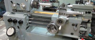
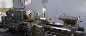
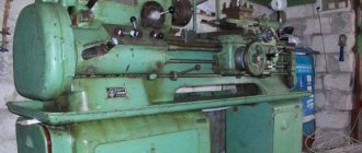
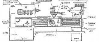
The 1M95 lathe is a typical representative of universal horizontal metal-cutting equipment. Designed for performing a variety of turning operations, as well as for cutting external threads on parts such as rotating bodies.
The most common operations are the production of stepped shafts, bushings and other axially symmetrical parts with holes, grooves and conical surfaces. The design of the unit allows its effective use in milling, slotting and drilling operations. The scope of practical use is repair and auxiliary shops and workshops.
History of creation and production
The combined turning-screw-cutting machine 1M95 was developed at the Design Bureau of the Alma-Ata Machine Tool Plant named after. 20 years of October (Kazakhstan). From the time of independence until 2011, the plant did not function, but has now resumed production of metal-cutting equipment.
The start of serial production of the 1M95 dates back to 1966, but 11 years later the machine was discontinued due to the creation of more modern models 1D95 and 1E95. At the production facilities of the enterprise, overhauls of turning and screw-cutting equipment of its own production, operating at machine-building enterprises of the republic, are also carried out.
In addition to Almaty, similar equipment was also produced sporadically at some defense enterprises of the former USSR under conversion programs, but mainly for their own needs.
Machine passport 1M95
This operating manual “ Passport of the 1M95 machine ” contains information necessary both for the maintenance personnel of this machine and for the employee directly involved in working on this machine. This manual is an electronic version in PDF format of the original paper version. This documentation contains the Passport and Manual (instructions) for operating the 1M95 screw-cutting lathe.
CONTENT
Purpose and brief technical characteristics
Transporting the machine
Foundation and installation of the machine
Preparing the machine for initial start-up
Machine passport
- Turning and milling unit
- Spindle
- Headstock
- Tailstock stand
- Support table
- Drilling unit
- Vertical milling head
- Slotting device
- Accessories and accessories
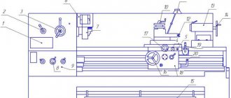
- General view of the machine with specification of controls
- Kinematic diagram
- Specification of gears, worms, screws and nuts
- Machine mechanics
- Mechanism of the main movement of the turning and milling unit
- Mechanism of the main movement of the drilling unit and vertical milling head
- Mechanism of movement of the slotting device
- Feed mechanism
- Setting up a thread cutting machine
- Bearing Specification
- Bearing layout
Description of the machine
Machine lubrication
- Lubrication scheme
- Lubrication map
Machine adjustment
Electric passport
Drawings of wearing parts
You can download the passport of the combined machine 1M95 in good quality from the link below.
Detailed description of the case
The body (bed) of the 1M95 lathe is characterized by the arrangement of two independent drives on a common base - for performing turning-milling and drilling transitions. The torque to perform these operations is provided by separate electric motors. That's why the machine is called combined.
The body was made of cast iron, so it has a complex box-shaped configuration. The internal cavities of the bed are reinforced with transverse stiffening ribs, which increase the stability of the 1M95 lathe when switching operating modes and reduce the deflection of the bed under operating loads.
There are two prismatic guides located in the upper part of the housing. The carriage with the working tool moves along the front, and the tailstock of the 1M95 lathe moves along the rear. Electric motors are mounted inside the hollow pedestals to operate the turning-milling unit and to control the drilling head. In addition to the main movement engine, the left cabinet also houses the gearbox control drive.
By means of a V-belt drive, the movement is transmitted to the gearbox. This unit contains a friction-mechanical unit, which, through a gear block, distributes movement to the desired feed chain, while simultaneously controlling the movement of the spindle. The control electric motor is of a reverse type, which allows you to obtain 6 different spindle speeds, respectively, in the forward and reverse directions.
To transmit torque, the feed box has coaxially installed gears that have different gear ratios. When connected to the desired pair of gears, the drive is switched to one or another rotation speed. This is used when setting up a 1M95 lathe to perform threading, turning or milling-slotting metalworking transitions.
The drive system for the drilling head of the 1M95 lathe is also installed in the left cabinet of the housing. From the electric motor, the torque is transmitted through a V-belt drive and a rigid cam clutch to the worm head.
Control of switching systems is achieved by using separate friction clutches. With their help the following is performed:
- Movement of the 1M95 lathe support in two mutually perpendicular directions;
- Automatic shutdown of drives in case of torque overload;
- Activation of the main movement mechanism of the drilling head.
The movements of the rest are made manually or by switching the corresponding handles, which are located on the control panel of the 1M95 lathe.
Control and feed of lathe 1M95, video
Dimensions
The 1M95 lathe has the following overall dimensions: Overall dimensions of the machine (length×width×height), mm - 2750×1255×1670, maximum working dimensions of the table (length×width), mm - 700×280.
Location of controls and their list
The control system for the 1M95 lathe includes automatic adjustment of cutting modes, control of the movement of the working tool during metalworking, and control of the operation of the lubrication system. This also includes mechanical overload sensors that disconnect the machine from the power supply.
The controls are located in the following areas. In the upper part of the left cabinet of the case there are handles for fixing and moving the lead screw, drilling table, adjusting and turning on the feed mechanism and gearbox.
In the central part of the body, on the support, there are handles designed to adjust the spindle speed and/or the number of strokes of the slotting device. There are also handles for engaging friction clutches, handwheels for manually moving moving parts, and buttons that control the operation of the lubrication station.
The right cabinet contains: adjusting screws for tensioning the V-belt drive belts, handles for reverse control of electric motors, handles that change the speed of the spindle.
In separate boxes, which are located at the bottom of the right and left stands, elements of the electrical control system for the 1M95 lathe are mounted. Grounding wires are laid along the rear of the housing.
List of controls
Landing and connecting bases
Device
The combined machine 1m95 has a classic layout with the usual arrangement of adjustment and mode settings. Certain types of additional equipment have individual installation rules. For example, according to the documentation, the sharpening device is recommended to be located separately from the main unit of equipment.
The 1m95 model bed provides high rigidity. It is made according to the classical design and has a box shape. The walls of the frame are reinforced with transverse ribs. The guides are of a prismatic type, one of them is designed to move the caliper carriage, the other moves the tailstock block. The frame is located on two base pedestals; the main drive, the electric motor itself and part of the electrical equipment for its control are mounted on the left.
The gearbox unit is capable of moving in a vertical direction. It is mounted on guides in the left area of the bed table. The rotational torque is transmitted to the gearbox via V-belts; the electric motor is located in the left base block.
The design of the gearbox ensures reliability, stable operation, fast switching, and provides familiar control mechanics using handles. It provides 6 switching stages for forward and reverse rotation, 12 speeds in total. The kinematics of torque transmission are familiar and standard, from the clutch platen and gear block to the feed chain and spindle.
The reliability and durability of the gearbox is achieved by using reliable materials. Gears are made of carbon steel that undergoes thermal hardening. In order for the structural elements to serve for a long time, you should not change the spindle speed during the working stroke.
The feed box when cutting threads can be easily adjusted using the appropriate handles. The choice of the desired type of thread can be made based on the table installed on the machine body (on the box panel).
The caliper block also has a familiar layout and design. It moves longitudinally along the bed table guides and transversely along the corresponding elements of the carriage structure. This can be done either mechanically or driven by a wheel, manually. The toolholder block has a permissible rotation angle of 45 degrees in each direction.
The mechanism is lubricated according to the instructions given in the equipment passport. The documentation indicates the types of oil, the frequency of maintenance and a description of the procedure, as well as the norms for filling technical fluid. Lubrication of individual components during operation of the machine is carried out either by natural splashing with intake from the bath (headstock), or by supply from a plunger pump (apron, guide carriages, etc.). A separate list of structural elements is lubricated only manually using an oil can.
Permissible spindle play
The permissible spindle play is determined by the characteristics of the installation location and the bearings operating in the structure. The recommended fit gap according to the accuracy class is 0.005 mm. The preload of the bearings is adjusted with a nut. The change in the fit gap is regulated by a detachable adjusting ring. It is ground until the desired value is achieved, then the bearing is installed and finally tightened with a second adjusting nut. You need to start work on adjusting the gaps with the inner ring, which must be ground according to the standard caliber KP-75.
Spindle and chuck runout tolerance
When installed on the spindle taper, the chuck can create backlash in three ways:
- lateral due to inaccurate positioning;
- lateral due to uneven pressure of the cams;
- end due to defects in flanges and spindle fit.
The tolerance of the chuck runout in combination with the structural runout of the spindle should be as small as possible. For accuracy class H, the limit is 50 microns. To achieve the required accuracy, it is necessary to bore the jaws, machine the landing cone, center and carefully adjust both the spindle and the chuck block separately.
Specifications
| Parameter name | 1M95 |
| Accuracy class according to GOST 8-82 | N |
| Maximum size/diameter of workpiece processed | 500 |
| The largest diameter of the workpiece above the caliper | 420 |
| The location of the centers relative to the frame guides, mm – adjustable | 235..355 |
| The height at which the spindle axis is located | 125..245 |
| Maximum length of the original workpiece (RMS) | 1000 |
| Maximum length of the workpiece area to be processed | 820 |
| Maximum weight of the workpiece that can be installed in the centers, kg | 100 |
| Headstock | |
| Maximum vertical movement of the headstock | 120 |
| Spindle | |
| Diameter of through hole in spindle | 35 |
| maximum outer diameter of the workpiece (strand) | 32 |
| Number of speed steps for direct spindle rotation | 12 |
| Spindle direct rotation frequency, rpm | 28..1250 |
| Number of spindle reverse rotation frequency steps | 12 |
| Spindle reverse rotation frequency, rpm | 28..1250 |
| Size of the inner cone in the spindle | №5 |
| Spindle braking | No |
| Support table. Submissions | |
| Dimensions of the working surface of the table | 280 x 700 |
| Maximum longitudinal movement of the caliper carriage | 820 |
| Maximum lateral movement of the caliper | 320 |
| Maximum lateral movement of the upper slide (cutting slide) | 110 |
| Number of longitudinal/transverse feed stages | 24/ 24 |
| Limits of longitudinal feed speed, mm/rev | 0,13..1,87 |
| Transverse feed speed limits, mm/rev | 0,072..1,016 |
| Speed of fast movement of the caliper, longitudinal/transverse, m/min | No |
| Longitudinal movement by one division of the dial | 1 |
| Transverse movement of the caliper by one division of the dial | 0,05 |
| Moving the cutting slide one division of the limb | 0,05 |
| Number of metric threads to be cut | 23 |
| Limits of pitches of cut metric threads | 1..12 |
| Number of inch threads to be cut | 24 |
| Limits of pitches of cut inch threads | 3..28 |
| Number of modular threads to be cut | 13 |
| Limits of pitches of cut modular threads | 0,25..35 |
| Number of cut pitch threads | 24 |
| Limits of pitches of cut pitch threads | 8..112 |
| Overload fuse | There is |
| Blocking longitudinal and transverse feeds | There is |
| Switching longitudinal stops | No |
| Surface roughness of a workpiece made of structural steel during finishing turning, microns, no more | Ra 2.0 |
| Tailstock | |
| The greatest length of movement of the tailstock along the bed | 820 |
| Maximum length of vertical movement of the tailstock | 120 |
| Maximum travel length of the tailstock quill | 165 |
| Maximum movement of the tailstock | ±20 |
| Inner cone size | №4 |
| Drilling unit | |
| Maximum diameter of the resulting drill hole | 25 |
| Maximum spindle stroke | 80 |
| Drill spindle axis overhang | 210 |
| Drill table diameter | 320 |
| Vertical movement of the drill table | 465 |
| Drill spindle inner cone size | №3 |
| Distance from spindle end to drill table | 40..540 |
| Overhang of the spindle axis of the milling head | 380 |
| Distance from the end of the spindle to the support table | 120..240 |
| Maximum longitudinal movement of the support table | 320 |
| Milling head inner cone size | №3 |
| Slotting device | |
| Cutter stroke length | 100 |
| Dolbyator caliper overhang | 310 |
| maximum depth of the resulting chiselling hole | 80 |
| Maximum chiselling length | 280 |
| Maximum dimensions of the area to be chiseled | 320 |
| Electrical equipment | |
| Number of electric motors on the machine | 4 |
| Main drive electric motor, kW | 4 |
| Drilling unit drive electric motor, kW | 1,1 |
| Grinding device electric motor, kW | 0,8 |
| Grinding device electric motor, kW | — |
| Cooling pump electric motor, kW | 0,12 |
| Total power, kW | |
| Dimensions and weight of lathe 1M95 | |
| Dimensions of lathe 1M95 (length width height) (RMC 1000) | 2750 x 1255 x 1670 |
| Weight of lathe 1M95 (RMTs 1000), kg | 2170 |
Length, diameter, depth are indicated in millimeters.
Kinematic diagram
Electrical diagram
Repair and restoration of turning machine 1M95
Repair and Restoration of turning 1M95
Mechanic repairman (January 22, 2014 — 22:47) wrote:
Remove the chuck and check the spindle runout and the bend.. For one and the PB near the chuck, check for the bend to see where there should be play.. I checked on the PB flanges there is practically no bend 0.002mm, the plan is not possible to unscrew the washer!
Post edited by Frezchik: 23 January 2014 — 02:46
Repair and restoration of turning machine 1M95
Frezchik (23 January 2014 — 02:41) wrote:
I can't unscrew the washer! Attached image: Photo-08804.jpgNow this is not necessary. Check the plan of the washer, then install the cartridge and check for the bend, the cartridge itself... Repair and Restoration of a 1M95 lathe The following measurements showed 1.- Runout of the plan of the front part of the washer where the cartridge sits 0.08mm. And the runout of the rear part of the washer is 0.08mm and also in the same place there is a runout as on the front part2. When measuring the outer surface of the neck, the plan of the washer where it is screwed onto the spindle, the arrow deviated by only 0.02..0.03mm3. The bending of the plan washer with a force of 25-30 kg, and about 400...500 mm long pipe inserted into the spindle, the indicator showed 0.04...0.05 mm in one direction, that is, if you press yourself, and the same amount in the other direction.4. When measuring the cartridge for bending, the indicator showed at a force of 25-30 kg within 0.05..0.06mm, but with a greater force it shows more clarity. If you pump with quick movements back and forth, the arrow jumps within 0.08...0.10mm
What are the conclusions, who will tell you in this situation?
Post edited by Frezchik: 23 January 2014 — 13:35
Repair and restoration of turning machine 1M95
Frezchik (23 January 2014 - 13:33) wrote:
Runout plan of the washer of the front part where the cartridge fits 0.08mm, the indicator showed 0.04...0.05mm in one direction. When measuring the cartridge on the bend, the indicator showed with a force of 25-30 kg within 0.05..0.06mm. Grind the faceplate definitely, but first tighten the bearings.. Bend measure in one direction.. Welded faceplate!? What cartridge? Repair and Restoration of a lathe 1M95 Frezchik, I had a similar problem. When cutting the workpiece there was severe crushing. I didn’t take measurements of the runout of the bearings, I decided to change all the spindle bearings with new ones. After disassembly, the thrust bearing was badly worn, the balls were almost square. Changed all bearings. After assembly and testing, the crushing decreased, but not by much. I lowered the headstock all the way, tightened the caliper wedges as much as possible, the crushing decreased further but did not disappear at all. Maybe this machine has weak frame rigidity. Regarding tightening the front bearing. On this machine, the preload in the bearing is produced by grinding the thrust half-rings and then tightening the nut inside the headstock. Tightening only the nut without grinding the half rings will not give any result. Repair and Restoration of a 1M95 Frezchik lathe. There, according to the passport, the bearing is assembled on the spindle and inserted into the machine. During bearing assembly, half rings are machined and the whole thing is clamped and only then inserted. There were also similar problems after I changed the bearing and reassembled it as stated in the passport, everything was fine. Well, it’s true that there are ripples when you cut a large diameter, but I don’t bother with that yet.
Post edited by Slonopotam7: 23 January 2014 — 23:25
Repair and restoration of turning machine 1M95
Farmer59 (23 January 2014 — 23:10) wrote:
Slonopotam7 (23 January 2014 — 23:24) wrote:
I also had similar problems after I changed the bearing.
Thank you very much guys, I even have a printed passport, here’s a small question, there should be a bearing like a high class (A) according to the passport, what kind of bearings did you install when you bought simple 3182115 without an accuracy class? Repair and restoration of turning machine 1M95
Farmer59 (23 January 2014 — 23:10) wrote:
Tightening only the nut without grinding the half rings will not give any result.
Yes, you are right, I tightened the internal nut but there was no change. So you will definitely have to sharpen and polish new rings? Repair and restoration of turning machine 1M95
Self-taught. Taught in the USSR. (13 January 2014 - 10:17) wrote:
Guys, we need help. When transporting the machine, they broke the plate (and lost the broken part) installed on the guitar, which is used when lifting the gearbox. So that the gears are engaged. Maybe someone can circle it on paper and send it to the post office.
Here is your plate Gennady, as promised! I posted it here, it might be useful to someone else! please forgive me for the incorrect spelling, I’m such a fucking draftsman
Post edited by Frezchik: 24 January 2014 — 04:02
Repair and restoration of lathe 1M95 at one time I had to work on such a machine. The impression is twofold. triune in three persons. Hence the mediocre characteristics of both turning and milling drilling. But an excellent machine for the home. the entire metal-cutting group at once + saving space in the home workshop. The main thing not to forget when working on it is that the spindle group is weak and processing large-diameter parts causes crushing, hence the frequent tightening of the clutches and carefully monitor the front support bearing (it has a tendency to collapse if there is excessive clearance) Repair and restoration of turning machine 1M95
Frezchik, Put here a picture of the spindle assembly, otherwise I have another machine downloaded, and I need to look for yours.. I’ll see what kind of bearings and rings are there..
Repair and restoration of lathe 1M95 mechanic repairman,
Mechanic repairman (January 24, 2014 - 05:00) wrote:
Put here a picture of the spindle assembly, otherwise I have another machine downloaded, and I need to look for yours.. I'll see what kind of bearings and rings are there..
Unfortunately, at the moment I can’t post a picture of the spindle, since I haven’t gotten around to it yet and haven’t disassembled it, I need to take measurements to get a detailed drawing. For the first time, the general drawing is in the passport; I printed the passport for myself a long time ago before purchasing the machine. And it’s useful to look for drawings of a spindle without any help; such a thing doesn’t exist on the Internet yet! Repair and restoration of turning machine 1M95
I started my 1M95 about a year ago, I also changed the spindle bearings, although I didn’t bother with ground washers, I threw them away, but the cleanliness of the processing did not improve from this, I started looking further, found out that there was play in the connection of the small longitudinal rotation flange (fastening the bolts pulled) I temporarily placed strips of copper foil under the back and front parts; I couldn’t get my hands around for grinding. I also noticed that when lowering the headstock to the end, the supporting protrusions on the front side do not come into contact with the frame, and it turns out that it hangs only on the column, and despite its apparent rigidity, it has some mobility, in order to limit it at least a little, I pressed the headstock with a crowbar (there is a gap where the roller for raising and lowering comes out) and slipped transformer iron plates under the supports. After this, cutting became normal, and when grinding the surface looked like chrome (not on St3).
Repair and restoration of turning machine 1M95
Frezchik, The front spindle bearing really has a higher accuracy class. I bought a Polish one in a store for 1.5 thousand, they said since the times of the USSR accuracy class 2, but according to rumors, one made in the USSR is more reliable but also more expensive. My machine doesn’t work well, I didn’t bother, I installed a Polish one.
Repair and restoration of turning machine 1M95
Farmer59 (24 January 2014 - 13:06) wrote:
I bought a Polish one in a store for 1.5 rubles, they said since the times of the USSR accuracy class 2,
Farmer59, Is it possible to find out where the 2nd accuracy class number was stamped on your bearing, why am I asking, I asked in one store where they sell bearings about the accuracy class, the seller’s eyes almost popped out of his head, he was talking about classes and I haven't heard! he showed me a similar bearing of some kind from our GPZ, only the last two numbers are different, there is a number (3) stamped on the inner race of the cone, it looks like the 3rd class, (1) or (2) most likely will not be found! Repair and restoration of turning machine 1M95
Frezchik, My bearing was in its original packaging in a box. On the box, in the marking column after the designation, the accuracy class is marked with a pen. But the inscription is very worn and cannot be read. The seller assured that it was definitely second class and pointed to the stamped number on the inner lens. In general, the accuracy class of the bearing used on this machine does not greatly affect the processing accuracy. In principle, any class can be used. But knowledgeable people told me that bearings produced by the GPZ of the former USSR are better than Polish ones. But keep in mind that when using a bearing of a certain class, for the accuracy of the mating, you need to use the table for the model of the installed bearing and the accuracy class of the bearing to find the preload value and calculate the thickness of the adjusting rings according to the example specified in the passport for the machine. The thickness of the rings is adjusted by grinding to the calculated size. Good luck.
Repair and restoration of turning machine 1M95
Frezchik, So I said that from the passport, otherwise I couldn’t find anything for this one...
Repair and restoration of turning machine 1M95
Farmer59, Well, wow, we have a Pole from storage 14 and 15, also one and a half pieces, Soviet, pulls a piece .. So you have it for nothing, with us for that kind of money you can buy some kind of remake ..
Repair and restoration of turning machine 1M95
Mechanic repairman (January 24, 2014 — 20:17) wrote:
So I said that from the passport, otherwise I couldn’t find anything for this one...
Here I posted a picture of the spindle as requested! It?
Post edited by Frezchik: 24 January 2014 — 22:13
Repair and restoration of turning machine 1M95
Oddly enough, I saw such rings on 1K62, but even without the Kashka ring it works perfectly.. You have one bearing on the back of the spindle, and for this reason, the designers had suspicions that the bearing would self-tension.. There is strong advice here I can’t, I need to ask the owners who removed the ring.. Or check without the ring, in turkey, how long the spindle goes, and before that check the same thing, but with the ring..
www.chipmaker.ru
Advantages and disadvantages
The advantage of the 1M95 lathe is its versatility and the ability to perform most metal cutting operations without significant changeovers, including turning (roughing and finishing), longitudinal and transverse milling, slotting, drilling and countersinking of vertical holes and cavities. When installing additional accessories, rough grinding of the surface is possible.
The presence of a universal thread-cutting head allows you to produce metric, inch and pitch threads on the 1M95 lathe, which is especially valuable when carrying out repair work and manufacturing spare parts for various pipelines.
The limitations of the unit are the relatively low durability of the switching systems. Friction clutches often fail due to wear of the working surfaces, and rigid clutches - due to chipping of the cam grooves. Restoring the latter is highly labor-intensive and often requires replacing the entire assembly. The reason for the intensive wear of control system elements is the high starting torque on electric motors and the stepwise principle of adjusting the speed of movement of moving parts.
To extend the period between overhauls and routine maintenance, it is recommended to use highly efficient lubricating and cooling media, which reduce the maximum temperatures in friction units, which reduces bearing wear.
Pros and cons, operating features of the 1M95 lathe, video
Combined machine 1M95
The combined machine model 1M95 is designed for work in mobile and stationary workshops. The machine consists of 2 main units: turning and milling and drilling, each with an independent drive.
Thanks to the variable height of the centers and the presence of a number of special devices: slotting, vertical and horizontal milling, sharpening, the versatility of the machine is achieved. It can be used for turning, milling, drilling, boring, slotting and cutting threads: metric, inch, modular and pitch; and also perform simple sharpening work.
Full set price
Since the 1M95 lathe is not mass-produced, only overhauled pieces of equipment are available for sale. It is advisable to purchase equipment through the marketing services of the relevant enterprises, which guarantee the operation of the machine and its compliance with current accuracy standards.
Depending on the region of the country, the cost of a 1M95 lathe ranges from 120...130 thousand rubles. Used machines are cheaper (from 50...60 thousand rubles), but since the actual resource of such equipment is unknown, it is not advisable to purchase it.
Electrical diagram of a 1A95 screw-cutting lathe
Electrical diagram of a 1A95 screw-cutting lathe
The electrical equipment of the machine (Fig. 3, 4, 5) is designed for a voltage of 380 or 220 volts of three-phase alternating current (Depending on the order) and consists of 5 electric motors with a squirrel-cage rotor, a control panel with buttons, a 1M electric motor switch, 2M electric motor switches, switches electric motors 3M, 4M, 5M and panels with equipment located in the right cabinet of the machine.
Local lighting is provided from the AC network through a step-down transformer 380/36 or 220/36 V. A bracket with fittings is provided for lighting fixtures.
The electrical equipment of the machine, which provides separate control of all electric motors and zero protection against overloads and short circuit currents, operates according to the scheme (Fig. 4):
