Purpose and scope
Due to its versatility, 1A62 lathes can be used to produce workpieces with cylindrical, conical and shaped configurations. And cut different types of threads - metric, inch, modular and pitch.
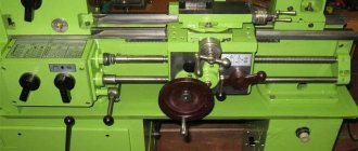
Experienced workers distinguish lathes by just one photo, but more complete information about the machine can be found by looking at the numbers in the name.
- “1” – designation of the group to which the lathe belongs.
- “A” – designation of the machine generation.
- “6” – designation of belonging to the screw-cutting group.
- “2” – this figure allows you to share the height of the center (above the bed), for this machine it is 22 cm.
Unlike other machines, 1A62 has expanded functionality and improved characteristics.
And the main improvements can be called:
- Increasing the spindle speed to 1200 rpm, plus the ability to choose from twenty-one forward rotation speeds and twelve reverse ones.
- Installation of a more powerful seven kilowatt engine.
- The main drive of the machine uses reliable wedge equipment.
- The friction clutch of the unit has a reinforced design.
- Installation of a reliable roller bearing in the spindle assembly.
- To prevent spontaneous detachment of the cartridges from the spindle assembly, which occurs when rotational movements in the engine stop, a special groove is provided to accommodate fuses.
- Precise threads are guaranteed by a gearbox with direct engagement of the lead screw.
- The front part of the machine apron has a dial, which is responsible for carrying out longitudinal feed through the support.
- Has a reinforced tailstock.
- The improved design of the tool holder allows it to be rotated in any direction, at any angle, without using the second hand.
- The machine has an improved cooling system, with an electric pump and reservoir located at the rear of the device.
- Installation of steady rests is possible to achieve the required rigidity when using long parts on a 1A62 lathe.
Manufacturer information
The 1A62 screw-cutting lathe was produced from 1948 to 1956 at the Moscow Machine Tool Plant named after. A.I. Efremova. Before the revolution, this enterprise belonged to the Bromley brothers and was engaged in the production of various metal products. The plant was nationalized in 1918, and four years later, at the request of the labor collective, it was renamed “Red Proletarian”. Along with the new name, the company received a new specialization: the production of machines for metal and woodworking. The plant began reconstruction and construction of new production facilities. And in 1923, the first turning equipment was produced - machines of the TN series of three standard sizes.
The key year for the “Red Proletary” was 1930, when the design of a more powerful standardized machine called DIP (“Let's catch up and overtake”) began. Just two years later the first machine was manufactured and tested, and by the end of 1932 the company produced the first 25 DIP-200. The next year, the company was already producing 300 machines per month, and in 1934 it began producing larger-sized DIPs with indices 300, 400, 500. At the end of the thirties, DIP-200, in accordance with the newly adopted ENIMS classification, received a new designation - 1D62. During the war, “Red Proletary” produced machine tools (including those specialized for the needs of the defense industry) and produced artillery shells.
After the war, “Red Proletary” not only produced new types of lathes, but also designed them for other factories, thus becoming the leading enterprise in the industry for turning equipment. In 1948, the plant began production of the 1A62 machine, which replaced the legendary DIP-200, and the following year mastered their mass production. In 1951 the enterprise was named after A.I. Efremov - Minister of Machine Tool Industry of the USSR in 1941-1949. In 1951, a prototype of the now famous 1K62 was created. Two years later, this model went into production and was produced until 1971. In total, more than two hundred thousand of these machines were produced during this period. In the sixties, the company mastered the production of specialized machines and CNC turning equipment.
Since 1971, “Red Proletary” began producing 16K20 machines, and two years later began mass production of them, and in various configurations: with copiers, indication, CNC, etc. In the seventies, the plant had the largest production volumes in its entire history and supplied machine tools not only to the CMEA countries, but also to foreign countries. Since 1983, the company began mass production of CNC machines. At the same time, the plant stopped production of 16K20 machines and switched to production of the MK6056 screw-cutting lathe.
In the early 90s, the company faced difficult times. First, the demand for CNC machines fell almost to zero, then for universal machines, and by the mid-90s, “Red Proletary” produces only a few hundred machines a year. In 1999, the plant moved to a new production site, but with only part of the previous equipment.
Over the next ten years, the plant made an effort to regain at least part of the domestic market, which during this time was filled with foreign products, but in general its efforts were not crowned with success. In 2011, the company stopped producing machine tools, and its new owners announced the leasing of production and office space as its main activity. In 2016, it was announced that the production of turning equipment (including CNC ones) would be resumed, but the plant has not yet recorded any significant success in this matter.
Technical capabilities
The lathe meets the standards of category “H”; the main technical characteristics of the device can be identified:
- Comes with a maximum diameter for workpieces - on the support -21 cm, above the bed - 40 cm.
- With a maximum length of workpieces that can be processed on a screw-cutting lathe of 75, 100 and 150 cm.
- With the maximum available weight for processing workpieces, when processing in a chuck - 500 kg, when processing using a center - 1500 kg.
Machine 1AT screw-cutting lathe
The 1A62 universal lathe is designed to perform a wide variety of turning, threading and drilling work. The machine allows you to cut metric, inch, modular and pitch threads.
This machine differs from the previously produced 1D62M machine in the following changes:
- The highest spindle speed has been increased to 1200 rpm. The spindle has 21 speeds in the forward direction of rotation and 12 speeds in the reverse direction.
- Main drive electric motor power increased to 7.0 kW
- Flat belt transmission replaced by V-belt
- The spindle speed is set by three handles
- Reinforced friction clutch
- The front spindle journal is mounted in a special adjustable double-row roller bearing
- At the front end of the spindle there is a groove for fuses that prevent the chuck from spontaneously falling off when the machine is stopped
- The feed direction of the caliper when cutting threads is changed using a reverse mechanism.
- The design of the feed box allows direct engagement of the lead screw for cutting precise threads
- To protect the feed mechanism from contamination and improve its lubrication, the groove for controlling the stepped cone is closed
- A longitudinal feed dial is installed on the machine apron
- The tailstock is significantly strengthened
- The design of the tool holder allows it to be rotated with one hand to any angle
- The design of the fixed stop is made more reliable
- An electric pump is installed on the rear leg of the machine to supply coolant from a reservoir located inside this leg.
This is interesting: How to correctly insert and remove a drill bit into a hammer drill, screwdriver and drill
Workspace dimensions
Overall dimensions of the machine suggest:
- Height – 121 cm.
- With a device area at RMC 750 – 251 by 158 cm.
- With a device area at RMC 1000 – 265 by 158 cm.
- With a device area at RMC 1500 – 317 by 158 cm.
- The machine weighs, not counting the electrical equipment at RMC 750 - 2,045 tons.
- Weight at RMC 1000, not counting electrical equipment - 2.105 tons.
- The machine weighs, not counting the electrical equipment at RMC 1500, 2,370 tons.
An example of a homemade lathe with drawings
Let's take a closer look at one of the working options for a lathe assembled on our own, the fairly high quality of which rightfully deserves the closest attention. The author of this homemade product did not even skimp on the drawings, according to which this device was successfully manufactured.
Of course, not everyone needs such a thorough approach to business; often simpler designs are built for home needs, but as a donor for good ideas, this machine is perfectly suited.
Controls
The front panel of the device contains the following unit controls:
- A handle that sets the required spindle rotation speed.
- The handle increases the thread of the workpiece.
- A handle that sets the left or right direction for threading.
- A handle that regulates the feed and thread pitch.
- A handle that operates a lead screw or a lead roller, which is used only for quiet running.
- A handle that regulates the forward or reverse rotation shaft of the motor on the main drive.
- A handle that changes the direction of the support when turning a part, switching between the longitudinal and transverse direction of feed.
- The organ that controls the apron.
- A handle that turns the mechanical feed mode on and off for using the flywheel, engaging the lead screw and moving the longitudinal slide.
- The handle, which controls the manual feed on the caliper, fixes the cutting heads, and moves part of the spindle.
- A handle that secures the tailstock, together with a flywheel that ensures its smooth movement.
Important!
Also, the presence of electrical switches to illuminate the workplace. Switch for the pump that cools the machine. And a button responsible for starting the engine.
Gearbox
There were 30 possible speeds for the gearbox, but due to a coincidence with the number of revolutions in the spindle assembly, their number was reduced to 21 different types.
The handle on the gearbox contains information about the number of revolutions of the spindle assembly and turns in different directions depending on the type of work until the pointer shows the required number of revolutions.
Reverse
Used for fixing parts.
Options:
- Comes with a diameter and size having a through shape - 3.6 cm.
- With an acceptable rod size of no more than 3.8 cm.
- With several stages of rotation (21 in forward rotation and 12 in reverse gear).
- With double-sided friction clutch.
Reverse is a defining tool for rotating the spindle head. In direct mode, the speed varies from 11.5 to 1200 rpm. With reverse rotation 18–1500 rpm.
Gearbox
The feed box provides metric, inch, modular and pitch cutting without the use of replaceable gears.
- Thread with metric pitch from 1 to 12 mm (19 steps).
- Thread with inch pitch from 2 to 24 threads per 1 inch (20 steps).
- Thread with modular pitch from 0.50 to 3 modules (10 steps).
- Thread with pitch pitch from 7 to 96 pitches (24 steps).
Apron
The apron is responsible for converting the rotational movements of the lead screw or roller into translational movements for the support (feed) along the direction of the bed.
The apron is located in the machine body, as standard facing the supports. Provides rotation of the worm wheel.
Caliper
Calipers 1A62, as on other similar models, are responsible for moving the cutting tools relative to the workpieces being processed. The condition of this part of the unit directly affects the precise performance of the work and the functioning of the machine.
The 1A62 support has the following technical capabilities:
- It will mix the longitudinal carriage at 65, 90 and 140 cm, the transverse carriage at 28 cm.
- It has longitudinal and transverse feeds in the amount of 35 pcs.
- The feed is made in the range of 0.082–1.59 mm/rev for longitudinal ones, and 0.027–0.522 mm/rev for transverse ones.
- Threads to be cut: metal 19 (pitch from 1 to 12 mm), inch - 20 (pitch - 2-24 threads/inch), modular - 10 (pitch - 0.5-3 modules), pitch - 24 (pitch - 7 –95).
Important!
The lathe uses a cutting slide to measure the accuracy in the movement of the cutting heads, which is controlled by several flywheels and special levers.
What has a positive effect on work performance:
- Maximum movement increases to 11.3 cm.
- With a maximum movement angle of 90 degrees, and a scale of one division indicates one degree.
- With a maximum holder cross-section of 2.5 by 2.5 cm.
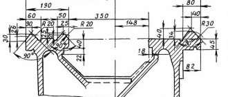
Purpose and design of the tailstock
The tailstock is a device that securely fastens the part when processing in the center or when installing a cutter.
The tailstock has the following characteristics:
- with a quill diameter securing the cutting tool – 70 mm;
- with an internal landing cone of category “Morse 4”;
- with a maximum movement of 15 cm, with one
- division of the dial quill moves by 0.1 mm;
- with a maximum lateral displacement (in both directions) – 15 mm.
Electrical equipment control
The levers of electrical equipment serve as a switch and switch from the network. Workplace lighting is also included. Responsible for the operation of the pump. They control the push-button station to turn the main engine of the machine on and off.
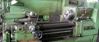
Design and operating characteristics of the main components of the machine
General view and layout of the 1K62 machine (Fig. 1)
The main components of the machine: bed 13, which serves to connect all components of the machine; headstock 2, which houses the spindle 4 of the machine and the gearbox; a support 11 on which the cutting tool is fixed; tailstock 15; feed box 3, transmitting rotation to the lead shaft 24 and the lead screw 23; cabinet 20 with electrical equipment of the machine; stands 22 and 29.
The machine bed 13 (see Fig. 1, a) rests on the left 29 and right 22 pedestals, to which it is rigidly fastened. The left cabinet contains the electric motor of the main drive of the machine. The right cabinet contains a pump that supplies coolant through a hose to the cutting tool. Liquid flows from trough 27 into the internal cavity of the cabinet. The most accurate position of the moving units of the machine is ensured by the combined frame guides - prismatic a and flat b (Fig. 1, b).
Headstock 2 is bolted to the left side of the frame. The inner part of the headstock contains a spindle 4 and a gearbox, covered with a lid on top.
If necessary, a rod processed on the machine can be passed through the through hole of spindle 4, and the front center can be installed in the conical socket of the spindle. At the right protruding end of the spindle there is a centering belt, a shoulder and a thread for precise alignment and fastening of the faceplate with chuck 5, into the cams of which the workpieces are installed.
The support 11 is designed to move the cutting tools attached to it and consists of the following main parts: a carriage 6, an apron 25, a transverse slide 7, a middle rotating part 8, an upper slide 10 and a quadruple tool holder 9 for installing and securing cutting tools.
Carriage 6 moves in the longitudinal direction along prismatic a and flat b guides (Fig. 1, b). Planks 1 and 2 of the carriage slide along the lower guides d and c. The carriage is moved manually in the longitudinal direction by rotating the flywheel 26 (Fig. 1, a).
The apron 25 is rigidly fixed to the carriage 6. It contains mechanisms that convert the rotational movement of the roller 24 and the screw 23 into the translational movement of the caliper.
To eliminate backlash in the screw drive, the screw nut consists of two parts, which are moved apart with a wedge. The middle part 8, together with the guides of the upper slide 10 located on it, which can be rotated relative to the axis of the machine at an angle and mounted on the transverse slide 7, is intended for processing conical surfaces of products.
The upper slide 10 is designed to move the cutter manually when rotating the handle 12. The exact amount of movement of the caliper is manually measured using dials with a division value of 0.05 mm
Feed box 3 serves to transmit rotation to the lead roller 24 or lead screw 23. The feed box is connected to the machine spindle by a transmission, which includes a set of interchangeable wheels located under the shield 1.
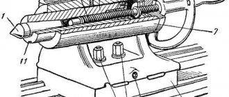
The tailstock 15 is designed to support the workpieces being processed with its rear center or to install and move axial tools. The main parts of the tailstock: plate 17, body 16, quill 14, clamping bar 1 (Fig. 1, c).
The tailstock moves along prismatic a and flat b guides (Fig. 1, c) of the machine bed. The movement is carried out either manually or using a caliper - if the tailstock is connected to it with a lock (Fig. 1, d). The lock consists of a bar 2 attached to the cross slide 1, a caliper and a bar 4 connected to the tailstock plate 3. By bringing the caliper to the tailstock and moving the slide 1 in the transverse direction, the protrusion of the bar 2 is inserted behind the protrusion of the bar 4. In this case, the tailstock is connected to the caliper and together with it will move in the longitudinal direction from the feed mechanism.
In order for the top of the rear center to be accurately located on the axis of the machine, the body 16 (Fig. 1, a) is moved in the transverse direction relative to the plate 17. To process conical surfaces of parts, the rear center is shifted with a screw 19 from the axis of the machine in the direction “toward” or "Push". Quill 14 has a tapered hole for mounting rear center or axial tools.
The electrical equipment of the machine is located in cabinet 20. On the front wall of the cabinet there is a panel 18 with an ammeter indicating the current of the main electric motor of the machine, and switches that turn on the machine to the electrical network, machine lighting and the electric motor of the pump supplying coolant.
Under cover 21 there is an electric motor for rapid movement of the caliper.
Recommendations for operating the equipment
In order for the unit to work efficiently, and for the produced parts to be of high quality and meet the parameters, the machine must be configured correctly.
The installation takes place on a specially prepared platform that can dampen vibrations from the load and withstand the weight of the machine.
The final setup of operating modes and rules of use are specified in the instructions included with the machine. Based on the experience of workers with these types of equipment, the accompanying documentation provides a clear procedure and instructions for operating the unit.
What are the main differences between the 1a62 model?
Before the manufacture of the 1a62g machine, there were other models, however, in the new model of the machine more functions and operations are available. Model 1a62 differs from the early release of model 1D62M in the following available functions:
- The maximum spindle speed has been increased to approximately 1200 rpm.
- Forward and reverse speeds are available.
- The power and strength of the electric motor is maximally improved to 7 kW.
- The transmission is proportionally replaced by a V-belt instead of the standard flat belt.
- The speed and number of revolutions can be easily set using three knobs.
- The front spindle is located in a special double-row bearing, which is adjustable.
- To prevent the gearbox and other mechanisms from becoming dirty, the groove is closed with a special device that helps improve lubrication.
- The operation of the tailstock has been improved, and thanks to this, the production quality is at the highest level.
- A dial is installed on a special apron, which stabilizes the longitudinal feed and improves the quality of its functionality.
- The gearbox consistently allows direct engagement, thanks to which cutting is carried out accurately and with virtually no mistakes.
- The fixed stop is strengthened much more powerfully and strongly, that is, the likelihood of damage and breakage is low.
- A cooler is installed at the rear of the machine, which cools the equipment and improves the quality of carving and overall production.
There is also a special groove for the fuse on the machine, which does not allow the cartridge to fall off even if the equipment itself stops.
Passport of the 1AT screw-cutting machine
This operating manual “Universal turning machine 1A62” contains information necessary both for the maintenance personnel of this machine and for the employee directly involved in working on this machine. This manual is an electronic version in PDF format of the original paper version. This documentation contains the Passport and Manual (instructions) for the operation of the 1A62 universal lathe.
CONTENT
Introduction Purpose of the machine Machine characteristics Kinematic diagram of the machine Machine design
- Stanin
- Headstock (gearbox)
- Tailstock
- Guitar
- Feed box (reversible)
- Apron
- Caliper
- Lunettes
Cooling of working tools Electrical equipment and control of electric motors
- Main drive motor
- Electric motor characteristics
- Electric pump
- Characteristics of the pump motor
- Electrical equipment
- Wiring
- Electrical circuit operation
Machine controls Lubrication of the machine Transportation, installation and test run of the machine Setting up the machine Setting up the feed chain Maintenance and adjustment of the machine Maintenance of the electrical equipment of the machine Specification of ball and roller bearings Specification of accessories for the machine 1A62 Spare parts of the machine Replacement gears for cutting particularly precise threads Instructions for adjusting the front bearing spindle of a screw-cutting lathe, model 1A62 Machine passport Download the first version of the machine passport 1A62. Screw-cutting lathe (95 pages) in good quality can be found at the link below:
This is interesting: Manual hydraulic press for car service - types of garage presses, their features and characteristics
1.3. Division of machines according to their masses
- Lightweight machines:
weight up to 1 t - Medium machines:
weight from 1 t to 10 t - Large machines:
weight from 10 t to 30 t - Heavy machines:
weight from 10 t to 100 t - Particularly heavy machines:
weight over 100 t
The technical characteristics of some heavy machines also contain the largest workpiece mass.
Accuracy indicators. The accuracy of metal-cutting machines is determined by three groups of indicators: characterizing the accuracy of processing of product samples; characterizing the geometric accuracy of machine tools; additional.
Indicators characterizing the processing accuracy of product samples include:
- accuracy of geometric shapes and location of processed surfaces of product samples;
- constancy of batch sizes of product samples;
- roughness parameters of processed surfaces of product samples.
Indicators characterizing the geometric accuracy of the machine include:
- accuracy of bases for installing workpieces and tools;
- accuracy of movement trajectories of the working parts of the machine, carrying the workpiece and tool;
- the accuracy of the location of the axes of rotation and the directions of linear movements of the working parts of the machine, carrying the workpiece and the tool relative to each other and relative to the bases;
- accuracy of interconnected relative linear and angular movements of the working parts of the machine, carrying the workpiece and tool;
- accuracy of dividing and installation movements of the working parts of the machine;
- accuracy of coordinate movements (positioning of the working parts of the machine) carrying the workpiece and tool;
- the stability of some parameters with multiple repetitions of the test, for example, the accuracy of approach to a hard stop, the accuracy of small approach movements.
Additional indicators of machine accuracy include the ability to maintain the relative position of the working parts of the machine carrying the workpiece and tool, provided:
- external load applications;
- exposure to heat generated when the machine is idling;
- machine vibrations that occur when the machine is idling.
Electrical diagram
Electrical wiring, automation and fuses are located on the electrical panel, which is hidden in a metal cabinet mounted on the machine bed . The electrical wiring diagram is divided into two parts: the primary power electrical circuit and the secondary control circuit. The primary circuit includes storage power equipment:
three-phase circuit breaker;- main engine switching contacts;
- contacts for switching on the rapid speed motor of the caliper;
- water pump switch;
- relay;
- circuit breakers.
Secondary circuit: transformer, start and stop buttons;