Tailstock
The tailstock is movable and is used to secure the part to the spindle. It consists of 2 parts: the lower one - the main plate and the upper one, which holds the spindle.
Sectional view of the tailstock
The movable upper part moves along the lower perpendicular to the horizontal axis of the machine. This is necessary when turning cone-shaped parts. A shaft passes through the headstock wall; it can be rotated by a lever on the rear panel of the machine. The headstock is fastened to the frame using ordinary bolts.
Tailstock
Each lathe is individual in its layout, the device and circuit may differ slightly in detail, but in small and medium-sized machines this option is most common. The layout and layout of heavy large lathes differs depending on their purpose; they are highly specialized.
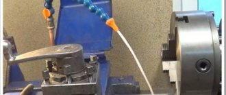
First start-up and equipment health check
To check the serviceability of the equipment, you must first run the machine at idle speed.
Each master configures the machine in his own way, depending on the intended work and functions performed. All elements must be checked sequentially; only after checking at idle speed can you turn off the machine and set certain parameters for operation. Before processing the workpiece, be sure to make sure that the wood is free of chips, deformations and cracks. The spindle should rotate without the slightest difficulty during operation. Be sure to check the coincidence of the centers of symmetry of the machine and the part.
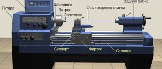
The device of the headstock of a screw-cutting lathe
The headstock or spindle headstock of a screw-cutting lathe is a cast iron box, inside of which the gearbox is located - the spindle speed switching mechanism.
The spindle is the main assembly of the headstock (spindle stock). The front end of the spindle has an internal conical bore with a No. 5 Morse taper, into which the front center and various fixtures for securing workpieces are inserted. At the front end of the spindle there is a landing cone along which chucks are installed to secure workpieces.
All gearbox shafts and the spindle rotate on rolling bearings, which are lubricated both by splashing (the gearbox is filled with oil) and by force, using a pump. The feed movement from the spindle is transmitted to the bit shaft and then to the feed mechanism.
Screw-cutting lathes have almost the same type of layout. The front spindle headstock is attached to the left end of the bed. It contains the machine's gearbox, the main part of which is the spindle. The movement is transmitted from the V-belt pulley. The interaction of gears is explained when describing the kinematic diagram. The spindle and all shafts are mounted on rolling bearings. The front spindle support contains a radial double-row roller bearing, in which preload is created by fitting the inner ring onto the tapered journal of the spindle. If you push the ring onto the cone with a nut, it expands and puts pressure on the rollers. The rear spindle support has two angular contact ball bearings that absorb radial and axial loads; The preload is adjusted with a nut tightening the inner rings. The gearbox shafts are mounted on tapered roller bearings, which is convenient for assembly and disassembly; Preload is adjusted using pressure screws. Since the shafts are long, they have a middle support.
On the left side of the friction clutch, which reverses the movement of the spindle, there is a large number of disks, since large torques are required in the forward direction of rotation. A special feature of gear blocks is the adhesive connections between the rims and the hubs. The wheel hub on the shaft is a band brake disc; The rod of the control mechanism, setting the clutch in the neutral position, turns on the brake (by pressing the roller). The wheel blocks are switched using flywheels and handles.
In some machines, the gearbox is located in the bed frame. In this case, it is connected to the spindle by a belt drive. Such machines are called split drive machines.
How the bed and headstock of the machine are arranged
The frame is a supporting element on which all other structural elements of the unit are installed and fixed. Structurally, the frame consists of two walls connected to each other by transverse elements that give it the required level of rigidity. Individual parts of the machine must move along the bed; for this purpose, it is equipped with special guides, three of which have a prismatic section, and one has a flat section. The tailstock of the machine is located on the right side of the bed, along which it moves thanks to internal guides.
The cast lathe bed is reinforced with stiffening ribs and has ground and hardened guides
The headstock simultaneously performs two functions: it gives the workpiece rotation and supports it during processing. On the front part of this part of the lathe (it is also called the “spindle head”) there are gearbox control handles. With the help of such handles, the machine spindle is given the required rotation speed.
In order to simplify the control of the gearbox, next to the shift knob there is a plate with a diagram that indicates how to position the handle so that the spindle rotates at the required frequency.
Speed selection lever for BF20 Yario machine
In addition to the gearbox, the headstock of the machine also contains a spindle rotation unit, in which rolling or sliding bearings can be used. The device chuck (cam or drive type) is fixed at the end of the spindle using a threaded connection. It is this unit of the lathe that is responsible for transmitting rotation to the workpiece during its processing.
The frame guides along which the machine carriage moves (the lower part of the support) have a prismatic cross-section. They are subject to high demands on parallelism and straightness. If these requirements are neglected, it will be impossible to ensure high quality processing.
Functional features and device
The tailstock and headstock of any lathe are important structural parts, each of which performs its own functions.
Headstock. The quality of the entire structure as a result depends on the precision of manufacturing of this part. A spindle is located on the headstock, which transmits torsional movement to the workpiece. The main elements of the headstock are:
- frame;
- spindle;
- bearings;
- design for controlling the direction of spindle movement;
- a device that controls the speed of the spindle;
- device for connecting and installing equipment.
Tailstock. This is the support unit of a woodworking lathe, which is designed to fix the workpiece. Main elements of the tailstock design:
- frame;
- quill;
- flywheel;
- flywheel handle;
- screw to move the tailstock laterally.
The tailstock has a hole in the quill into which a tool is inserted to process the part. During the working process, the headstock moves along the bed to select the optimal distance depending on the length of the workpiece being processed.
Node purpose
The tailstock of a metal lathe is a reliable support for securing the workpiece. In addition, it supports the second edge of the workpiece and ensures its stable rotation. During drilling, it is connected to the support with a grip. A drill of the required diameter is inserted into the quill chuck. In addition to drills, mounting is provided for: dies, taps, reamers, countersinks and other cutting tools. Such a wide range of tools used allows for a wide range of processing operations.
Adjustment
In order to maintain the tailstock on a lathe in proper working order, it must be periodically adjusted, and in case of malfunctions, it must be repaired in a timely manner.
First, you need to set the part as it should, adjust it and center it, and then adjust all the parameters of this unit. Periodic adjustment is needed for the following reasons:
- gaps may appear between the bearings and the spindle body (if we are talking about a turning unit where the quill rotates);
- the center of the assembly may shift relative to the quill, then adjustment will be needed;
- There may be play in the fastening of the headstock to the frame and other reasons.
The first time the tailstock is adjusted is when the machine is put into operation.
The tailstock is repaired as it fails, when its faults are clearly visible. Typical signs that a part needs to be sent for repair may include the following:
- the workpiece processing mode has changed;
- beats appeared during the rotation of the workpieces.
The spindle repair process is considered the most labor-intensive and costly. You can’t do this without turning skills, and the machine itself must be available. The difficulty lies in restoring the accuracy of the hole (boring followed by finishing) in which the quill is fixed.
The process is complicated by the fact that the outer surface is cylindrical, while the inner surface is conical. In addition, the quill itself is made of a very durable material - it is “hardened” alloy steel.
After repair, check the mechanism for radial runout: with proper troubleshooting, it should be zero, the tailstock will not “knock” and will restore all its original characteristics.
Step-by-step assembly and installation yourself
After studying the diagrams and drawings, you can proceed to the assembly and installation of both components of the lathe. Then you will need to set up and configure the equipment.
Headstock
Algorithm for making the headstock:
- Turn out a cylindrical body with a wall thickness of 10 mm.
- The channel, which will be necessary to make a drain for attaching the headstock to the frame, is welded to a corner of sheet steel.
- Attach the headstock to the stand.
The cylindrical body has the following dimensions:
- outer diameter – 56 mm;
- length – 18 cm;
- mounting sockets with a diameter of 24 mm for bearings;
- shaft diameter – 30 mm.
Tailstock
Tailstock manufacturing algorithm:
- weld 2 bolts together to increase the overall length;
- make a rotating center from a pipe of such diameter that the outer race of the bearings fits tightly into it;
- If necessary, you can make a 2-3 mm wide cut in the resulting sleeve;
- the future wall of the rotating center has the same diameter as the outer race of the bearing;
- scald the washer and nut on the right side;
- Tighten the left nut and cut the horses flush with the washer;
- cut off the head of the bolts, clamp the bolt itself into a drilling machine and refine it using an abrasive stone.
Then you need to make the spindle housing. For this:
- Take a piece of pipe with a diameter of ¾ inches, 6-7 cm long.
- Nuts are welded at both ends.
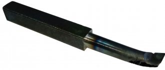
- The tailstock cone is also made from a bolt.
Before installation, first grind the cone shank to such an extent that it fits into the inner race of the bearings. To support the outer race, before installing the bearings, install a ring of bent wire with a diameter of 1-2 mm into the housing.
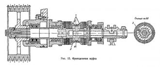
The device of the tailstock of a screw-cutting lathe
The general view and layout of the tailstock of a screw-cutting lathe is shown in Fig. 33.
The tailstock serves to support the workpiece during processing in the centers and represents a second support.
When drilling, the tailstock is connected to the caliper carriage with a special clamp and receives mechanical feed from it. The drill is inserted into the quill instead of the center.
The tailstock must satisfy the following conditions:
- under no circumstances move arbitrarily
- give the correct position of the center axis
- enable quick installation along the machine axis
- provide the ability to accurately position the workpiece on both center holes of the machine
- ensure reliable direction of the spindle (quill) of the tailstock and its clamping without disturbing the position of the axis
The stability and reliable position of the tailstock axis are necessary conditions for obtaining satisfactory results when machining on centers and eliminating the possibility of accidents due to the workpiece being pulled out of the centers. This depends on how the tailstock housing is secured to the frame.
The designs of tailstocks are very diverse, but their basic concepts have much in common. Therefore, knowing the basic structure of the tailstock of any medium-sized universal lathe, you can easily understand the design of the tailstocks of other lathes.
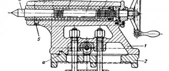
Let's look at the design of the tailstock of a lathe. The tailstock body of this machine, like most other types of machines, consists of two parts: the body itself 1 and the base (raft, bridge) of the tailstock 2.
The raft (bridge) is scraped along the frame guides, and the body is installed on its upper surface.
The planes of contact between the body and the raft are scraped so that the axis of the tailstock coincides in height with the axis of the machine spindle and is parallel to it. Parallelism of the axes is achieved by scraping the vertical edge of the guide bead on the raft. Lateral alignment of the axes is achieved by moving the body along the raft using a square-head screw and nut. The body is attached to the raft and at the same time to the frame using two bolts 4 and a lining 3.
Achieving coincidence of the axes of the spindles of the headstock and tailstock by scraping the supporting planes of the headstock body requires a significant investment of time. Therefore, as a rule, during a major overhaul, the coincidence of the axes of the headstock and tailstock is achieved by boring the hole for the tailstock spindle. In this case, it becomes necessary to replace the tailstock spindle, which is finally machined along the outer diameter only after boring the tailstock body.
The tailstock spindle (quill) 7 is a hollow cylinder, the front edge of which is made in the form of a Morse cone into which a center 6 or drill is inserted, and a nut 9 is inserted into the rear edge. Using this nut and a screw 8 with a flywheel 10, the spindle can move along the axis . Key 5 protects the spindle from turning. The spindle is clamped with a handle, which has right and left threads at the end for clamping nuts. When the spindle is retracted completely into the tailstock, screw 8 with its end rests against the end of center 6 and pushes it out of the spindle body. Thus, in this design, knocking the center out of the cone is very convenient.
In heavy machines, the spindle does not have a nut, the cutting is done directly on the spindle, and the flywheel bushing is a nut. It is impossible to knock out the center from the end of such a spindle. Therefore, ordinary centers are not suitable for such spindles; the centers should be threaded. A nut is screwed onto the thread, with which the center can be pressed out, or flats are made on the centers, which make it possible to turn the center with a key and thereby release it from the socket. The use of simple centers on these machines should be prohibited, since they are pressed in and can only be knocked out by hitting a sledgehammer or heating the spindle with blowtorches. This leads to damage to the spindle cone.
When processing flat cones, it is necessary to shift the center of the tailstock in the transverse direction. For this purpose, the tailstock body and the base are connected to each other by a transverse key. The transverse displacement of the headstock body relative to the base is made by screws and a nut.
Design and principle of operation
Despite the differences in the structure of the tailstocks of many machines, the scheme of their operation and production in most cases is approximately the same. Based on this, we can put together a general diagram of the structure of this part in most machines. The classic design of this structural element will look like this:
- Center shank is conical type.
- Control knob.
- Screw for rotation.
- Pinol. A movable hollow part, made in the shape of a cylinder, is designed to fix the rotary screw. Using a special key, the quill (spindle) is secured against rotation. The spindle is fixed using a special handle, which has direct and reverse threads. This part can be completely retracted into the tailstock assembly.
- Screw.
- Lever.
- The basis.
- Plate.
- Screw.
- Pins.
- Keyway type groove.
This unit has a hole in the spindle where tools for working with workpieces are installed. During operation of the machine, the unit is moved by the bed to select the appropriate distance depending on the size of the workpiece. Taking into account the specifics of the work performed, the spindle can be configured for both rotating and stationary parts. All movements of this unit are carried out as part of the preparatory work.
The assembly in the device moves by engaging the protrusion of the bars. In the same case, automatic movement of the caliper is activated. The unit can be moved parallel to the frame using a special handle. This is done if it is necessary to secure the workpiece in the centers, to bring the cutting surface to the part and to change the position of the turret head.
In machines with small parameters, the spindle moves using a special gear located in the bracket. On large machines, the unit is driven by an electric drive. The spindle moves in the direction of the axis, and it does not depend on what is fixed in it - the working tool or the workpiece.
Headstock spindle
The spindle is a hollow shaft made of carbon steel, into the hole of which long workpieces are passed. The spindle is installed in the headstock housing using front and rear bearing units.
The spindle end of foreign-made lathes complies with ISO 702/1. On modern CNC machines, depending on consumer requests, the geometry of the spindle end can be changed. A clamping device is installed at the end: a lathe chuck, a collet, a faceplate, and a thrust center.
The seating surfaces of the spindle end are processed at least grade 6 (in precision machines it is much higher), during manufacturing the surface is hardened and ground (Ra not lower than 1.25), and its outer diameter is strictly concentric with the axis of rotation. Otherwise, the radial and axial runout of the chuck or other clamping device installed on the spindle will exceed the permissible values. This will affect the processing accuracy of the workpiece.
In this regard, when replacing clamping equipment, the spindle seating surfaces must be protected from various types of damage, and the runout of the newly installed chuck or collet must be checked.
Accuracy check
The geometric accuracy of processing, for example, on CNC lathes is checked in this way: a workpiece with a diameter of 200 mm and a length of 500 mm is clamped into a lathe chuck and turned along a cylindrical surface without pressing the tailstock. The permissible deviation from cylindricity is 0.04 mm at a length of 300 mm from the end of the cartridge.
If the results are unsatisfactory, the headstock of the lathe is adjusted: setting optimal clearances in the angular contact and thrust bearings of the spindle, which absorb radial and axial force during operation of the equipment.
Tailstock device
In any lathe, the basis is the bed. The headstock of the lathe, the main controls, and the tailstock are mounted on it. The latter have quite varied designs. The main elements perform the same functions and are built according to identical circuit diagrams.
These elements are:
- the base on which all devices and controls are located;
- fastening element - quill;
- all-metal body;
- control handles (allow you to fix the quill and the body of the entire headstock);
- a wheel for moving the quill (also called a flywheel);
- adjusting screw (allows you to firmly fix the position of the tailstock relative to other elements of the lathe).
A drawing of the tailstock of a lathe allows you to understand the kinematic diagram and the interaction of all elements.
The base is an all-metal plate that rests on the right side of the frame. The housing is located on the base. It houses the tailstock chuck of the lathe. In the front of the quill there is a hole in which the tool is placed. It is made in the shape of a cone.
The center of the tailstock is connected to the caliper. Translational motion is transmitted through it. This is ensured by the presence of an independent feed drive. In certain types of units, rotational motion is produced. It is ensured by the design of the tailstock quill. The horizontal movement of the quill is carried out using an electric motor or a hydraulic mechanism. The choice of drive method depends on the tasks being solved and the modification of the machine.
All products must meet the following requirements:
- ensure the exact location of the center of the structure;
- facilitate quick installation along the horizontal axis of the machine;
- ensure precise direction of movement towards the spindle while maintaining alignment during rotational movement;
- securely fixed in the selected position.
Ensuring stability and reliability of fastening allows you to maintain a given class of processing accuracy.
The simplicity of the design and the availability of components allows you to make this part of the lathe yourself. With high-quality assembly, a homemade tailstock of a lathe will perform basic functions no worse than the factory one.
Podruchnik
This element conditionally consists of two parts. For both, you need one type of workpiece - a 50 mm corner, inside of which another, 30 mm wide, is inserted. They are welded along the edges, in the end you should get two sections of 260 and 600 mm.
The short part is the adjustable base of the hand rest. One of the shelves is cut off, but not completely, leaving a 110 mm long section with an inclined cut. The other shelf is cut at a right angle 60 mm from the rear edge. You need to make a counter frame from a thick steel plate that will clamp the guide of the tool rest.
To make a guide with a clamp, take a regular one-inch pipe and make a longitudinal cut in it with a grinder. The resulting sleeve should be about 150 mm long; we insert it into a 25 mm corner, orienting the slot outward perpendicular to one of the shelves. We tighten the parts with a clamp and weld along the entire length closest to the shelf slot. We cover the workpiece with a second corner of the same length and attach it to the tube from the back side.
The guide is welded flat to the protruding flange of the adjustment rail on its inner side. For fixation, a screw with a long handle and a nut welded to the rail are used. On the reverse side, the strike plate is fastened with a cotter pin or even a welded rod.
The handrail is mounted on a 20 mm smooth reinforcement rod, which is located centrally on the outside of the corner blank. The rod fits tightly into the tube of the guide system, and when the screw is tightened, it is securely pressed on all sides. A long corner piece 600 mm long is welded to the rod with a slight inclination toward itself and a slightly “sharpened” leading edge.
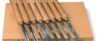
The best wood lathes
A tabletop wood lathe will perform operations such as turning, sanding, grooving and threading. The specificity is the use of hand cutters and shaped devices. To fix the working tool, a hand rest is used, which is installed between the front and rear support.
The VyborExperta.ru project team suggests paying attention to 4 models that will help you process wood with impeccable quality. The equipment is distinguished by good functionality and reliable electric motors, an easy-to-use format
Encore Corvette-74
Stationary wood lathe for the home workshop with a powerful electric motor. With a weight of 77 kg, it has good stability, which has a positive effect on the quality of processing of wooden workpieces. An asynchronous electric motor rotates the spindle at a speed of 500 to 2000 rpm. The distance between centers of 845 mm allows you to process balusters and other large parts. When working with compact workpieces, a faceplate is used.
The variator is responsible for smoothly adjusting the spindle speed. A belt drive helps reduce the load on the electric motor. The manufacturer's assortment includes a copier that can be purchased additionally to increase productivity. For processing parts with a diameter of more than 300 mm, the headstock has a rotating design.
Advantages:
- Adjustable tool holder;
- Reliable protection against spontaneous start-up;
- Base as standard;
- The engine is designed for intensive work;
- Low price.
Flaws:
Insufficient motor power for workpieces larger than 300 mm in diameter.
Einhell 1000/1
The development of German engineers attracted attention with its light weight, powerful engine and four-speed gearbox. The electric motor accelerates the spindle to 2600 rpm. The engine is designed for intensive, long-term operation, which allows the machine to be used in small workshops for the production of carpentry. The double frame ensures good stability of the equipment.
The dimensions of the machine are suitable for workpieces with a diameter of up to 280 mm. A special feature of the tailstock design is a rotating spindle, which simplifies the fixation of the part. A faceplate is provided for working with small workpieces.
Advantages:
- Low price;
- Easy to adjust caliper;
- Stop included;
- Low noise level;
- The maximum length of the workpiece is 1 meter.
Flaws:
It gets hot when working intensively with damp wood.
Skrab 57000
Tabletop machine with a powerful electric motor that spins the spindle at a speed of 5000 rpm. The speed control is stepless, the torque is transmitted using a toothed belt drive. The equipment can be used for processing wood and plastic. It is possible to connect a proprietary flexible shaft.
The maximum length of the workpiece to be processed is 300 mm, diameter – no more than 40 mm. This makes the equipment attractive for model designers, jewelers, and souvenir producers. The machine is attached to the coordinate tables via rubber supports, which reduce vibration. The guide has an ideal surface and is made of an aluminum-based alloy that is resistant to corrosion.
Advantages:
- Protective casing made of durable plastic;
- Low power consumption;
- The speed is regulated automatically;
- Designed for intensive work.
Flaws:
High price for its class.
Record Power DML 305
Desktop model with 370 W motor with stepwise spindle speed adjustment. The electric motor is designed for long-term operation under load, and 6 speeds allow you to solve problems of any complexity. This makes the equipment relevant for professional workshops. The heavy cast iron frame is durable and provides good stability when paired with two massive supports.
The tailstock spindle has a lock with a division scale. This guarantees the accuracy of the settings. Speed shifting is carried out using ergonomic pulleys, which are very easy to access. The model is designed for processing parts with a length of 393 mm, but it is possible to purchase a bed extension for workpieces up to 1 meter.
Advantages:
- Build quality;
- Workpiece diameter up to 305 mm;
- Good equipment;
- Wide range of additional options;
- Stable operation under load.
Flaws:
- Overcharge;
- There is no headstock rotation function.
Electric motor for machine
The basis of the lathe drive is the engine. When choosing this unit, it is important to pay attention to its main characteristic – power. For a home machine, models with a power from 1200 to 2000 W are suitable. The type of connection is important; there are single-phase and three-phase motors.
In a low-power table lathe, you can use a motor from a washing machine. It is unlikely to cope with the processing of large workpieces, but it will help produce small decorative elements and kitchen utensils.
Woodworking Machine
The woodworking equipment market offers an extensive line of wood lathes. Each consumer makes his choice taking into account his interests, but the main criterion is the drive power. For a home workshop where turning work is performed sporadically, a simple tabletop machine with an electric motor power of 1 kilowatt and a spindle speed of 3500 rpm is suitable.
The main components and mechanisms of a wood lathe correspond to the classic structure of a lathe, which processes workpieces by rotation. Three main mechanisms:
- drive - electric motor, single-phase or three-phase;
- transmission - a set of devices that transmit the rotation of the motor shaft to the spindle head;
- the executive is the support.
Four main nodes:
- bed - the body on which the mechanisms are fixed;
- front spindle headstock - for attaching a faceplate or lathe chuck;
- rear fixing headstock - for installing a rotating center or drill chuck.
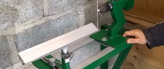
Design feature
You can assemble a wood lathe with your own hands from available materials. The design is simple and does not require much time to manufacture. The main part of the machine is a bed made of a channel, in which a groove is cut along the central center line with a grinder for fixing the tool rest and tailstock. The fixation principle is an eccentric mechanism.
Caliper structure
A lathe support is a unit that ensures the fixation of the cutting tool, as well as its movement in the inclined, longitudinal and transverse directions. It is on the support that the tool holder is located, moving with it due to a manual or mechanical drive.
Support with carriage for machine Optimum D140x250
The movement of this unit is ensured by its structure, which is characteristic of all lathes.
- The longitudinal movement, for which the lead screw is responsible, is performed by the caliper carriage, while it moves along the longitudinal guides of the frame.
- Transverse movement is performed by the upper - rotating - part of the support, on which the tool holder is installed (such movement, due to which the depth of processing can be adjusted, is carried out along the transverse guides of the support itself, which are shaped like a dovetail).
Quick-change tool holder MULTIFIX cartridge type
The tool holder, also called the cutting head, is installed on the top of the support. The latter can be fixed at different angles using special nuts. Depending on the need, single or multiple tool holders can be installed on lathes. The body of a typical cutting head has a cylindrical shape, and the tool is inserted into a special side slot in it and secured with bolts. There is a protrusion on the bottom of the cutting head that fits into a corresponding slot on the support. This is the most typical tool holder mounting scheme, used primarily on machines designed to perform simple turning work.
Making the front (back) headstock
headstock for a homemade drill machine
For a homemade machine, you can make a headstock with your own hands. Suitable:
- wooden board;
- thick plywood (10 mm);
- a metal sheet of small thickness that can be cut with metal scissors.
It is easier to make a headstock if a drill is chosen as the basis for the lathe. You need to make a stand with your own hands, where the drill will be fixed rigidly and its axis will be strictly horizontal.
Both centers of the headstocks must be firmly attached; this is an important condition. The tailstock should be able to move along the axis of rotation and be firmly fixed in the right place
The type of electric drive and its power are selected with your own hands, depending on the future purpose of the lathe. But the engine power should not be less than 250 W, otherwise nothing sensible can be turned on the machine.
Detailed video about the design of the headstock:
This is interesting: Safety valve - device, purpose, operation, types
DIY front and rear quill
The spindle head is a priori the most complex element of all equipment. During manufacturing, it is necessary to take into account that you will need a block of replaceable gears that transmit and change the speed of the rotational movement of the spindle and the torque directly from the gearbox shaft.
The tailstock is made with a movable or fixed center of rotation. For a movable version of the center, you will need to install a pair of bearings in the quill hole: the front edge with a conical roller, it will be thrust and the rear, radial, bored to a cone.
Installation and fixation of the rear center on the machine is carried out due to the conical hole of the sleeve. The spindle and thrust head are the basis of the design of any lathe.
Therefore, the master must know the principle of their operation, how to make such a part with his own hands and how to adjust it, and, if possible, repair it.
Repair cost
| Type of work | Price |
| Spindle Prevention | 9,000 rub. |
| Troubleshooting clamping devices | 19,000 rub. |
| Burnout (damage) of the stator winding | 30,000 rub. |
| Replacing bearings with rotor balancing | 50,000 rub. |
| Replacing spindle sensors | 10,000 rub. |
| Maintenance | 10,000 rub. |
| Non-standard work | 10,000 rub. |
| Major renovation | 50,000 rub. |
| Modernization of machine tools | 30,000 rub. |
Our main specialization is machine repair
If your machine does not work, our specialist will arrive as soon as possible and fix it. Call and consult by phone: 8
- Thanks to the use of modern devices, we can more accurately identify faults. And we save your money on repairs
- If your machine does not break down as usual. We will send it to our technicians and they will solve any problem
Read useful information:
Machine support repair
In the modern world, various machines are widely used, because... they allow you to perform many operations. This unit consists of many parts, where the main role is played by the machine support. And it often happens that the work of the tool freezes due to the breakdown of the caliper or other parts.
Further
Types of production machines, their setup and maintenance.
To work effectively with machine tools, you need to understand the types and purposes of machines, be able to carry out setup and independent maintenance. In this article we will analyze the main types of machines and general setup rules.
Further
Machine head repair
The headstock is an important element of the machine. If this part fails, it is very difficult to cope with the repair yourself and you have to contact specialized workshops
How to prevent breakdowns, what is important to know when doing your own repairs and how much the services of qualified craftsmen cost - all this can be found in the article
Further
Repair of coordinate machines
What is a coordinate machine? How to repair it yourself and is it worth it?
Further
Causes of machine gearbox malfunctions, methods for eliminating them, cost
The article talks about common failures of the gearbox of a lathe. Their causes and ways to eliminate them yourself are described. The approximate cost of repairing a machine gearbox in Moscow is also given.
Further
When concluding a long-term service agreement, you receive a discount of up to 20%. Don't forget, we have a guarantee on all types of work.
- engineer - mechanic
- CNC programmer
- Service engineer
- Electrician
- Electronics engineer
- Locksmith - repairman
Spindle as an element of a lathe
The most important structural component of a lathe is its spindle, which is a hollow metal shaft with a conical inner hole. What is noteworthy is that several structural elements of the machine are responsible for the correct functioning of this unit. It is in the inner conical hole of the spindle that various tools, mandrels and other devices are fixed.
Spindle drawing of screw-cutting lathe 16K20
In order to be able to install a faceplate or a lathe chuck on the spindle, its design includes a thread, and to center the latter there is also a collar on the neck. In addition, to prevent spontaneous unscrewing of the chuck when the spindle is quickly stopped, some models of lathes are equipped with a special groove.
The results of machining parts made of metal and other materials on the machine largely depend on the quality of manufacturing and assembly of all elements of the spindle assembly. In the elements of this unit, in which both the workpiece and the tool can be fixed, there should not be even the slightest play that causes vibration during the rotational movement. This must be carefully monitored both during the operation of the unit and when purchasing it.
What does cone 7 24 mean?
The main purpose of the 7:24 tool cone is CNC machines equipped with a unit for automatic tool change. This type of cone does not have the disadvantages inherent in the Morse taper, which is fixed by self-jamming, which is difficult for automatic installation into the machine spindle.
Interesting materials:
What is a complex sentence with coordinating and subordinating relationships? What is military service? What is a service contract and what are its forms? What is a tornado, its characteristics and consequences? What are adjacent? What is humility in the Bible? What's wrong with the Department of Internal Affairs? What are lexical archaisms themselves? What is the salinity of the waters of the World Ocean? What is salt nicotine?
Repair of turret lathe
Turret lathes are used in the continuous production of metal products. This common variety is used for almost all types of turning work. They are characterized by the presence of a turret head, which is a rotating unit with several positions for installing a cutting tool and the ability to perform various processes in automatic mode.
The mechanical, electrical and electronic parts of the machine are repaired. Repairs can be planned or unplanned. The first is due to the system of maintenance and repair of equipment and is carried out after a specified time or when a certain technical condition of the equipment is reached. The second type of repair is also included in equipment maintenance, but is carried out unscheduled.
There are two types of repairs to turret lathe equipment – routine and major. The first is a repair to ensure the operability of the equipment (or preventive) for a certain time. Individual parts or assemblies are replaced or repaired. The second type of repair is carried out to ensure long-term operation of the equipment and prevent breakdowns.
Types of breakdowns
The most common malfunctions of turret lathes include several.
- There is no normal rotation of the gearbox gears and gear shifting. The cause may be low oil pressure in the hydraulic system. To eliminate the malfunction, you need to adjust the pressure with a pressure spool. This malfunction also occurs in the absence of adjustment of the locking spool on the hydraulic friction cylinder rod (there is no pressure on the gear rotation mechanism). To eliminate this, it is necessary to set the clutch fork to the middle value and the locking spool to the position of supplying pressure to the mechanism for slowly turning the gears. The third reason may be a breakdown of the slow rotation mechanism. Eliminated by ensuring ease of movement of the spools and rack piston. Another reason is the breakage of the pins and screws on the gear coupling (characterized by the shearing of the pins and screws of the gear coupling when the gears are turned slowly). Eliminated by replacing the pins and screws on the gear coupling. Increased pipe connection leaks can also cause this problem. It can be eliminated by replacing the tube or tightening the fittings (the location of the leak is determined by the pressure drop on the pressure gauge in this area).
- The hum of the hydraulic system and lack of lubrication can be caused by air leaks in the suction line. The problem is eliminated by sucking in air (you need to tighten the connections) and adding oil to the specified level.
- An increase in spindle braking time occurs due to a decrease in pressure in the hydraulic system. It can be eliminated by adjusting the pressure to 25 kgf/cm (braking time must be at least five seconds).
- Increased wear of the clutch fork is caused by a lack of adjustment of the clutch fork travel limiting nut. Eliminated by adjusting the pressure to 25 kgf/cm. Braking time 5-6 sec during machining
Overhaul of turret lathes involves a large amount of work. The equipment is disassembled into components, which, in turn, are disassembled into parts. It is mandatory to diagnose the condition of components and parts, polish some of them, and replace some with new ones. After all repair operations are completed, the units are first assembled, and then general assembly is carried out. At the final stage, the operation of the machine is checked. At the same time, it must fully comply with electrical safety standards.
The work that is carried out during a major overhaul of a machine has a certain sequence. Before disassembling, the machine is checked and the wear of the rubbing surfaces is assessed. Then the machine components are completely disassembled, the condition is assessed and the parts are washed (a document of defective parts is drawn up). After this, either restoration or replacement of parts, repair of the cooling system, hydraulic unit, and electrical equipment are carried out.
If necessary, the lubrication system pumps are repaired or replaced, and the guide surfaces are polished. As a rule, guide cleaners and quills are replaced. At the end of the repair, the machine components are assembled, its operation is checked (consists of idling at all speeds and checking for accuracy/noise/heating). If necessary, all untreated surfaces are painted. It should be remembered that repairing the machine yourself can lead to adverse consequences.
Peculiarities
The area of use of any machine depends on its design features. This machine unit has the following main features:
- Multiple speeds and feeds. This allows the worker to select the optimal method for processing a particular part.
- You can carry out milling, end tool processing, and grinding (both inside and outside the part).
- The feed box is structurally similar to the unit with which milling machines are equipped. In addition, there is a speed change handle for convenient operation.
- The headstock has corners that are rounded. This is typical for devices that were produced in the sixties in the USSR.
- The guides of the device are quite strong, extremely accurate and durable. This is due to their careful grinding during the production of the device. In addition, the machine is equipped with an independent lubrication system powered by an electric hydraulic power station. It provides lubrication of the guides.
- The built-in gearbox makes it possible to cut different types of threads. The worker does not need to change gears every time.
- The preselectivity of the gearbox allows you to quickly and smoothly switch modes.
- Structurally, the device is designed in such a way that there is no need to service its rear part. This is especially convenient for industrial premises with a small area.
- There is a container with electrical equipment and a container for coolant and lubricant.
- The machine has a built-in container for metal filings. If necessary, it can be quickly emptied.
- There is a fuse that prevents the feed mechanism from overloading.
- The device is equipped with a vernier, which makes it possible to determine with high accuracy how transversely the caliper element has moved.
- Device speeds can be controlled mnemonically.
- The cutter head is fixed without gaps, which ensures high processing accuracy.
- The lead screw is automatically lubricated as the thread is formed.
- The spindle assembly is designed so that there is no need to dismantle it when changing drive belts.
We recommend watching a video review of the control handles:
Spindle
The name of this element comes from German and is translated as “spindle”. This part is a shaft that is equipped with a mechanism for fastening the workpiece that is being processed. Usually the shaft is made with a hole in which the rods are processed. The spindle neck is conical or cylindrical.
Basic standards for spindle operation:
- Wrapping accuracy - it is adjusted based on standards, and has a direct dependence on the purpose of the device itself, its accuracy.
- The rigidity of the spindle assembly itself - this requirement is also met based on generally accepted standards.
- Vibration resistance is in no way a determinant of the quality of the workpiece.
- Spindle speed - the higher the speed of this unit, the higher the quality of the finished product.
- Load-bearing capacity - this parameter almost entirely depends on the quality of the spindle supports and the fluid for lubricating the device.
- Durability - this item depends only on the quality of the bearings.
- Heat allowed for bearings.
One of the main conditions for the manufactured part to be processed as accurately and accurately as possible is the correct torsion of the spindle. It should rotate evenly and easily.