Tailstock of a lathe. Construction and repair of the tailstock
The device of the tailstock of a screw-cutting lathe
The general view and layout of the tailstock of a screw-cutting lathe is shown in Fig. 33.
The tailstock serves to support the workpiece during processing in the centers and represents a second support.
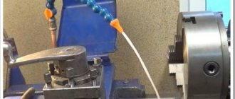
When drilling, the tailstock is connected to the caliper carriage with a special clamp and receives mechanical feed from it. The drill is inserted into the quill instead of the center.
The tailstock must satisfy the following conditions:
- under no circumstances move arbitrarily
- give the correct position of the center axis
- enable quick installation along the machine axis
- provide the ability to accurately position the workpiece on both center holes of the machine
- ensure reliable direction of the spindle (quill) of the tailstock and its clamping without disturbing the position of the axis
The stability and reliable position of the tailstock axis are necessary conditions for obtaining satisfactory results when machining on centers and eliminating the possibility of accidents due to the workpiece being pulled out of the centers. This depends on how the tailstock housing is secured to the frame.
The designs of tailstocks are very diverse, but their basic concepts have much in common. Therefore, knowing the basic structure of the tailstock of any medium-sized universal lathe, you can easily understand the design of the tailstocks of other lathes.
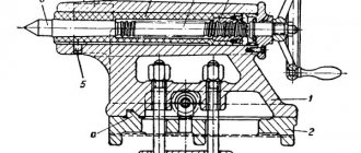
Let's look at the design of the tailstock of a lathe. The tailstock body of this machine, like most other types of machines, consists of two parts: the body itself 1 and the base (raft, bridge) of the tailstock 2.
The raft (bridge) is scraped along the frame guides, and the body is installed on its upper surface.
The planes of contact between the body and the raft are scraped so that the axis of the tailstock coincides in height with the axis of the machine spindle and is parallel to it.
Parallelism of the axes is achieved by scraping the vertical edge of the guide bead on the raft.
Lateral alignment of the axes is achieved by moving the body along the raft using a square-head screw and nut. The body is attached to the raft and at the same time to the frame using two bolts 4 and a lining 3. Achieving coincidence of the axes of the spindles of the headstock and tailstock by scraping the supporting planes of the headstock body requires a significant investment of time. Therefore, as a rule, during a major overhaul, the coincidence of the axes of the headstock and tailstock is achieved by boring the hole for the tailstock spindle. In this case, it becomes necessary to replace the tailstock spindle, which is finally machined along the outer diameter only after boring the tailstock body.
The tailstock spindle (quill) 7 is a hollow cylinder, the front edge of which is made in the form of a Morse cone into which a center 6 or drill is inserted, and a nut 9 is inserted into the rear edge. Using this nut and a screw 8 with a flywheel 10, the spindle can move along the axis . Key 5 protects the spindle from turning. The spindle is clamped with a handle, which has right and left threads at the end for clamping nuts. When the spindle is retracted completely into the tailstock, screw 8 with its end rests against the end of center 6 and pushes it out of the spindle body. Thus, in this design, knocking the center out of the cone is very convenient.
In heavy machines, the spindle does not have a nut, the cutting is done directly on the spindle, and the flywheel bushing is a nut. It is impossible to knock out the center from the end of such a spindle. Therefore, ordinary centers are not suitable for such spindles; the centers should be threaded. A nut is screwed onto the thread, with which the center can be pressed out, or flats are made on the centers, which make it possible to turn the center with a key and thereby release it from the socket. The use of simple centers on these machines should be prohibited, since they are pressed in and can only be knocked out by hitting a sledgehammer or heating the spindle with blowtorches. This leads to damage to the spindle cone.
When processing flat cones, it is necessary to shift the center of the tailstock in the transverse direction. For this purpose, the tailstock body and the base are connected to each other by a transverse key. The transverse displacement of the headstock body relative to the base is made by screws and a nut.
Tailstock of lathe 1k62. Assembly drawing
Tailstock of a lathe. Assembly drawing. View enlarged
Tailstock of lathe 16k20. Assembly drawing
Tailstock of a lathe. Assembly drawing. View enlarged
Repair and restoration of the tailstock of a lathe
When repairing the tailstock, the accuracy of the mating surfaces of the bridge with the frame and the body, the accuracy of the body opening and the height of the centers of the front and rear stock are restored, the quill, feed screw and other parts are repaired or remanufactured.
The most labor-intensive operations are to restore the accuracy of the hole in the body for the quill and restore the height of the centers.
The hole for the quill in the body is repaired by lapping, boring, followed by finishing, and using acrylic plastics.
Laps usually repair lightly worn holes. In this case, the height of the centers is restored by placing compensation pads on the guides and a new quill is made.
When repairing by boring, the height of the centers is simultaneously restored. After boring, the hole is usually finished with laps, and the quill is made of a larger diameter.
Acrylic plastics restore both the precision of the quill fit and the height of the centers. In this case, the quill is not manufactured, but repaired.
This repair method is the most effective, since it requires 3-5 times less time and money than the first two methods.
The two options for repairing the tailstock discussed below clearly confirm the profitability of repairs using acrylic plastics, in particular styracrylic of the TSh brand.
Repair of the tailstock housing and bridge without the use of acrylic plastic
The repair sequence is as follows:
- The surface of the 9th body is scraped (Fig. 60). The number of paint prints must be at least 10 on an area of 25 X 25 mm
- The surface 10 of the bridge 8 is milled and the cover is installed with glue or screws. If the bridge protrusion is tightly coupled with the housing groove, this operation is not performed
- The surfaces of the bridge mating with the hull are scraped (along the hull). The number of spots when checking for paint is at least 10 on an area of 25 X 25 mm. The protrusion of the bridge must fit tightly into the groove of the housing (without play)
- The surfaces of the bridge are scraped along the frame guides. The number of paint prints is 10-15 on an area of 25 X 25 mm. At the same time, when scraping, the surface mating with the body is ensured to be horizontal with an accuracy of 0.05 mm per 1000 mm of length. The check is carried out using a level installed on surface 9 along and across the frame guides. The frame is installed and leveled, while the plane for attaching the feed box must be positioned strictly vertically.
- Attach the bridge to the hull
- The bead rod is secured in the spindle of the machine headstock. The axis of the bead rod at the point where the cutter is attached must be 0.05 mm higher than the normal position of the spindle axis, for which: the measuring rod of the indicator, mounted on the machine support, is brought to the upper generatrix of the bead rod (at the point where the cutter is attached) and this position is fixed; loosen the front bolts securing the headstock (the spindle axis is already aligned parallel to the frame guides), use a lever to slightly raise the front part, place 0.02-0.05 mm thick foil under the front ends of the guides and secure the headstock to the bed; bring the indicator to the upper generatrix of the bead rod and notice its new position, in which the axis of the bead rod should be located 0.05 mm above the spindle axis.
- Install the tailstock in front of the caliper carriage and apply a weight for rigidity
- Boring the hole for the quill in the tailstock body (in 2-3 passes), spindle rotation speed 250 rpm; feed 0.1 mm/min. In this case, the surface finish must be no lower than V5, taper - no more than 0.02 mm, ovality - no more than 0.01 mm.
- Grind the hole in the body using an expanding mandrel mounted in the spindle and sandpaper. Spindle rotation speed 500-800 rpm, feed 10-15 m/min. Surface finish V7, taper - no more than 0.02 mm, ovality - no more than 0.01 mm
- The hole in the body is fine-tuned using a cast iron lap. Spindle rotation speed 200-300 rpm, feed - 5-8 m/min. In this case, a surface cleanliness of V 8 is achieved, the taper should be no more than 0.01 mm, and the ovality should be no more than 0.005 mm.
- Remove the foil from under the headstock guides and secure the headstock to the bed. The tailstock is assembled with a newly manufactured and fitted quill. The movement of the quill should be smooth, without backlash. The clamp should ensure reliable fastening of the quill.
- Check the position of the quill in relation to the bed guides and the coincidence of the centers of the front and rear stock, in accordance with the technical specifications in accordance with GOST 42-56.
The considered tailstock technological process is widely used in many factories, despite its significant labor intensity.
Restoring the tailstock with acrylic plastic
Restoring the tailstock with acrylic plastic is very simple and effective, since operations on precise boring and finishing of the housing hole are eliminated and it is possible to preserve the old quill. Bridge repairs are carried out in the same way as for repairs without acrylic plastic.
The technological process of restoring the hole in the tailstock housing includes the following operations:
- The hole for the quill in the body 4 of the tailstock (Fig. 60) is bored on a boring or lathe, and a layer of metal equal to 2-3 mm is removed. The cleanliness of the processing must correspond to V 1, taper and ovality are allowed no more than 0.5 mm.
- In the spindle 2 of the headstock 1 of the machine, the axis of which is adjusted to be parallel to the bed guides, a hollow mandrel with a plug 7 is installed. The outer diameter of the cylindrical part of the mandrel corresponds to the outer diameter of the repaired quill and has a size 0.01 mm larger than the quill. The mandrel is installed eccentrically relative to the spindle axis by 0.07-0.08 mm. To do this, a gasket shaped like a truncated cone with a thickness of 0.07–0.08 mm is placed in the conical hole of the spindle before installing the mandrel. The material for the gasket is paper or foil. The shape of the gasket (truncated cone) ensures uniform runout at both ends of the mandrel.
- By rotating spindle 2, check the runout of the mandrel, which should be no more than 0.15-0.18 mm, and install the spindle so that the generatrix of the mandrel with the largest positive deviation is located above the spindle axis. This arrangement of the mandrel ensures that the difference in height between the centers of the headstock and tailstock (0.05-0.07 mm) is established in accordance with the requirements of the technical specifications.
- In the body of the tailstock 4, three holes with a diameter of 6-8 mm are drilled above the hole for the quill; holes are located in the middle and along the edges of the body
- Degrease the bore of the housing and dry for 15-20 minutes until the solvent has completely evaporated.
- A thin, even layer of soap is applied to the mandrel, the tailstock body is installed and bolted to the frame.
- The hole for the quill (the space between the mandrel and the headstock body) is sealed with rings and plasticine 6; The holes of the quill fastening devices are also sealed, and three funnels 3 and 5 are installed from plasticine above the three drilled holes.
- Prepare an acrylic solution and pour it into the middle funnel. Filling is completed when the mass of styracrylic partially fills the outer funnels
- The flooded tailstock is kept in place for at least 2 hours at a temperature of 18-20 ° C
- They move the tailstock, protect the body from plasticine and tides of plastic, make lubrication grooves, drill holes, chisel the keyway and assemble the tailstock
Tailstock quill repair
This process involves grinding the outside diameter and restoring the taper bore by installing an expansion sleeve.
The compensation sleeve (Fig. 61, a) has a cylindrical shape on the outside and a cone on the inside. The bushing is often made from case-hardened steel, with the cone hardened to HRC 58-60. The wall thickness of the bushing near the largest diameter of the cone is taken to be 2 mm or more (depending on the diameter of the quill).
The outer diameter of the bushing is made according to the bored hole of the quill with a gap of 0.05 mm, the cleanliness of the machined surface is V5-V6.
The bushing is glued into the quill and after hardening (after 24 hours), the conical hole is ground.
As an example, we give the technology for restoring the tailstock quill of a screw-cutting lathe model 1E61, which consists of two stages:
- manufacturing an expansion sleeve (Fig. 61, a)
- quill repair (Fig. 61, b)
- The sleeve is machined with technological allowances, Morse taper No. 3, for grinding the interference is 7-8 mm, not counting the allowance of 5 mm. Cement to a depth of 0.8-1.2 mm. Remove technological allowances, leaving 1 mm per side. Kalat, HRC 58-62. The outer diameter and ends are machined according to the drawing (checked on a cone mandrel).
- Bore a hole in the quill Ø30A to a length of 90 mm (check for runout with an accuracy of 0.05 mm, finish V 5). Install the bushing with epoxy glue and keep it for 24 hours at a temperature of 18-20° C. Insert plugs on both sides, center them with an accuracy of 0.02 mm, grind the quill along the top to size and trim the front end, chamfering. Grind the outer diameter to size. The lubrication groove is milled according to the sketch. The numbers are engraved according to the sketch. Remove the plugs. Then the quill is aligned with an accuracy of 0.01 mm, the Morse taper No. 3 is ground on the cork and the front end is clean.
A quill repaired using this technology has increased wear resistance of the tapered hole, and the cost of repair is significantly lower than the cost of manufacturing a new quill.
Repair of the tailstock bridge of a screw-cutting lathe 1k62
Boring the tailstock of a screw-cutting lathe
Lapping the tailstock of a screw-cutting lathe
Adjusting the tailstock of a lathe
Literature
- Borisov G. S. and Sakharov V. L. A short reference book for a shop mechanic. M., publishing house "Machine Building", 1966.
- Gelberg B. T. Factory experience in modernizing machine tools. Lenizdat, 1960.
- Gelberg B. T. and Pekelis G. D. Issues of technology and organization of equipment repair. M., Proftekhizdat, 1960.
- Gelberg B. T. and Pekelis G. D. Repair of industrial equipment. M., publishing house "Higher School", 1967.
- A unified system of scheduled preventive maintenance and rational operation of technological equipment of machine-building enterprises. M., publishing house "Machine Building", 1967.
- Klyagin V.N. Technical conditions for the repair of metal-cutting machines of normal accuracy. M., publishing house "Machine Building", 1967.
- Pekelis G.D. and Minkin A.S. Repair of metal-cutting machines. Lenizdat, 1962.
- Pekelis G. D. and Gelberg B. T. Restoration and strengthening of process equipment parts. M., publishing house "Machine Building", 1964.
- Pekelis G. D. and Gelberg B. T. Mechanization of metalwork and repair work. M.-L., publishing house "Machine Building", 1967.
- Pekelis G. D. and Gelberg B. T. Repair of metal-cutting machines and forging and pressing equipment according to standard technological processes. M., publishing house "Machine Building", 1967.
- Pekelis G. D., Gelberg B. T. and Gordin Yu. N. Centralization and specialization of equipment repair in a production association, LDNTP, 1967.
- Pronikov A. S. Calculation and design of metal-cutting machines. M., publishing house "Higher School", 1967.
- Sheingold E. M., Nechaev L. N. Technology of repair and installation of industrial equipment. M.-L., publishing house "Machine Building", 1966.
- Shchebrov V. M. Repair of machines and mechanisms. M., publishing house "Higher School", 1964.
- Yakobson M. O. Machine tool technology. M., publishing house "Machine Building", 1968.
Useful links on the topic
Catalog directory of metal-cutting machines
Passports and manuals of metal-cutting machines
Directory of woodworking machines
Buy a catalog, directory, database: Price list of information publications
Pekelis G.D., Gelberg B.T. L., "Mechanical Engineering". 1970
stanki-katalog.ru
Lathe 1K62 - technical specifications, passport, device
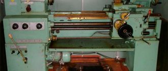
The 1K62 lathe, which was produced in Moscow for quite a long period (1956–1971), is well known to almost everyone involved in metalworking. After the end of production of this lathe model, which many can recognize in the photo below, it was replaced by the 16K20 unit.
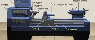
Universal screw-cutting lathe 1K62
Advantages of the model
The 1K62 machine, as follows from its characteristics, is included in the category of frontal type turning equipment. In other words, it is suitable for turning screw-cutting work with parts of large diameter and short length.
At the same time, the 1K62 screw-cutting lathe is a universal device, the technical capabilities of which ensure the execution of the entire range of turning operations. With such a device you can cut threads and turn disks and shafts of various configurations. What is important is that all operating modes of such a machine are very easy to configure. Due to the high rigidity of the lathe components of this model, ensured by the use of special bearings in its design, it can process parts that have undergone pre-hardening.
Main components of the 1K62 machine
The most significant advantages for which the 1K62 machine is especially appreciated by both professionals and novice specialists include the following.
- Feed and rotation speed can be adjusted over a wide range.
- The kinematic chains of the lathe in question, its individual components and structural elements are distinguished by high strength and rigidity.
- Using tools with mineral-ceramic and carbide cutting parts, such equipment can effectively cut workpieces.
- The design of the device, equipped with a powerful drive, is designed in such a way that it can effectively counteract vibration loads.
- This lathe comes standard with replaceable gears that drive the feedbox from the headstock.
- High-precision machining of parts on the 1K62 lathe can be carried out even in the presence of shock loads (their effect is compensated by special bearings).
- A special electric motor with a power of 1 kW is responsible for moving the unit’s support. The output shaft of such an electric motor, which ensures rapid movement of the caliper, rotates at a frequency of up to 1410 rpm.
- The tailstock of the equipment can move in the transverse direction, which allows the 1K62 screw-cutting lathe to be used for working with workpieces that have the shape of a shallow cone.
- The electrical circuit of the machine contains fusible links and thermal relays that protect it from short circuits and serious overloads during operation.
- The spindle assembly of the 1K62 lathe is equipped with heavy-duty bearings.
In situations where a drill is attached to the tailstock to form holes in workpieces, it can be rigidly connected to the bottom of the caliper using a special locking device, in which case it can be moved using a mechanical drive.
The 1K62 machine, the design of which was developed more than 60 years ago, can be equally effectively used to perform both power and high-speed turning operations (this cannot be said about every modern unit).
Controls of the 1K62 machine
Often, during turning operations, it becomes necessary to limit the movement of the machine carriage in the longitudinal direction. The technical capabilities of 1K62 also provide for this possibility; for this, a special stop is used, fixed on the shelf of the frame on its front side. When using it, the speed of movement of the caliper is limited (no more than 250 mm/min).
The standard equipment of the 1K62 lathe also includes two steady rests - movable and fixed. Such technical devices are known to be used to eliminate deformation of long workpieces during processing. Thanks to the movable steady rest, fixed on the machine carriage, workpieces with a cross-section from 2 to 8 cm are processed, and the fixed one, placed on the bed guides, allows you to work with parts with a cross-section from 2 to 13 cm.
Technical characteristics and passport of the machine 1K62
All technical characteristics of the 1K62 screw-cutting lathe are presented below in table format:
Characteristics of 1K62 - part 1 Characteristics of 1K62 - part 2 Characteristics of 1K62 - part 3
Download for free the passport of the screw-cutting lathe 1K62: Passport of the machine 1K62
Download repair and maintenance manual 1K62: Repair of machine 1K62
Design features of the machine
The tailstock of the 1K62 lathe, consisting of a plate, a body with a mounting hole and a retractable quill, can move along the bed guides. Adjustment of the reach, fixation of the quill and rear center, which are installed in the tailstock, are carried out using a special handle. The mounting hole in the quill has a conical shape, which allows you to fix various tools in it: drill, reamer, countersink, tap, etc.
Kinematic diagram 1K62 (click to enlarge)
The gearbox of the 1K62 machine and its tailstock are distinguished by the simplicity of their design, which is based on a number of shafts (one of them is frictional). A pulley is located on one of the gearbox shafts, to which torque is transmitted from the device’s electric motor. In addition, the box contains a friction clutch, various blocks (triple, intermediate, etc.), supports and rolling bearings. A special oil pump is responsible for lubricating all moving parts of the gearbox.
Gearbox mechanism
Tailstock 1K62
The longitudinal and transverse movement of the machine support occurs thanks to the lead shaft and lead screw, the rotation speed of which is regulated by the 1K62 feed box. In the design of this machine unit, which is responsible for the feed speed, the following elements can be distinguished: a three-stage Norton block, shafts, switchable couplings, interlocked gears, and bearings.
The feed box is located at the bottom of the equipment frame, which greatly facilitates its maintenance and repair. The shaft of this box is driven into rotation using replaceable guitar wheels, through which it is also connected to the spindle of the device, which ensures consistency between the rotation of the spindle and the feeds made by the support of the unit. A wheel moves along the feedbox shaft, at one end of which there is a gear, and at the second there is a handle that can be installed in one of ten positions.
Feed box device
The most important element of the lathe apron is the nut, which is in connection with the lead screw and ensures the longitudinal movement of the caliper. The nut, which often fails due to wear, has the ability to self-align relative to the lead screw, which ensures accurate movement of the caliper.
The machine apron, in which the rotation of the lead shaft and lead screw is converted into longitudinal movement of the carriage and transverse movement of the support, operates according to the following scheme.
- Rotation from the drive shaft is transmitted to the worm wheel through several successively arranged gears.
- The movement of the caliper, possible in four directions, is ensured by couplings with end teeth, which are engaged at the required moment.
To engage the queen nut and engage it with the lead screw, a handle located on the face of the machine apron is used. The simultaneous use of the drive shaft and lead screw to impart longitudinal movement to the caliper is eliminated, for which a special shaft with cams is responsible.
Apron of machine 1K62
The support, the most important device of a lathe, consists of such structural elements as:
- upper sled, which is also called incisor sled;
- cross carriage;
- bottom slide.
The movement of the carriage along the guides of the lower slide is ensured by a screw and a backlash-free nut. Rotation of the screw can be transmitted through a handle (manual control) or a gear wheel (automated control). On the upper surface of the carriage there are circular guides with a rotating plate. The design of this plate also provides guides on which a four-position tool holder is installed.
Machine support 1K62
The characteristics of such a unit and its design features make it possible to install a rotating plate and, accordingly, a tool holder with a tool at any angle to the longitudinal axis of the machine. To fix the rotary plate in the required position, special clamping bolts are provided in the carriage design. Even a novice turner can use such a device if he carefully studies the instructions for the equipment.
Other important components in the machine design
The design of the lathe also includes an electrical system, which can be familiarized with by studying the technical data sheet of the device. Such a system consists of three electrical circuits with different characteristics:
- a control circuit, the operation of which requires a voltage of 110 V and a current with a frequency of 50 Hz;
- power circuit operating from a voltage of 380 V and a current with a frequency of 3 to 50 Hz;
- the electrical circuit that is used to ensure the operation of the machine’s lighting equipment is voltage 24 or 36 V, current frequency 50 Hz.
Electrical diagram of the 1K62 machine (click to enlarge)
The drive of 1K62 lathes is a 10-kilowatt electric motor, the shaft of which can rotate at a frequency of 1450 rpm. Although the equipment passport describes how to start the machine and configure all its characteristics, it is not recommended to carry out such procedures without special knowledge and skills. This is explained by the fact that both the kinematic and electrical circuits of this equipment are considered quite complex in their design.
Certain models of lathes, which is necessarily indicated in their passport, are initially designed in such a way that their power circuit can be powered from an electrical circuit with a voltage of 220 V. It should be noted that this is rather an exception to the rule, since the basic models of the 1K62 lathe require voltage power supply 380 V. Before connecting the machine, it is very important to ensure that its neutral and solidly grounded wires are carefully insulated.
Article rating:
Loading…
Share with friends:
met-all.org
Caliper 1k62
| № | Name | Marking |
| 1 | Screw with caliper nut | 1K62-04-22/16 |
| 2 | Caliper wedge | 1К62-04-23 |
| 3 | Caliper (middle part) | 1K62-04-12 |
| 4 | Tool holder assembly | 1K62-04-21 SB (Ø 90) |
| 1K62-04-300 SB (Ø 110) | ||
| 5 | Caliper assembly | 1K62-04-001SB |
| 6 | Cam clutch | 1K62-04-24 |
| 7 | Upper part of the caliper | 1K62-04-17 |
Apron 1k62
| № | Name | Marking |
| 1 | Nut uterine | 1К62-06-63 |
| 2 | Shaft - gear of the 9th axis | 1K62-06-310 |
| 3 | 5th axis shaft | 1К62-06-118 |
| 4 | 7th axis shaft | 1K62-06-113 |
| 5 | 11th axis shaft | 1K62-06-112 |
| 6 | 12th axis shaft | 1K62-06-179 |
| 7 | 13th axis shaft | 1K62-06-110 |
| 8 | 14th axis shaft | 1K62-06-115 |
| 9 | 16th axis shaft | 1K62-06-116 |
| 10 | 17th axis shaft | 1K62-06-117 |
| 11 | Roller | 1K62-06-232 |
| 12 | 10th axis roller | 1K62-06-103 |
| 13 | 12th axle fork | 1K62-06-28 |
| 14 | 14th axle fork | 1К62-06-29 |
| 15 | Peephole | 1K62-06-253 |
| 16 | Dividing ring | 1K62-06-315 |
| 17 | Copier (drum) 13 axis | 1K62-06-82 |
| 18 | Handle body | 1K62-06-83 |
| 19 | Handle body | 1K62-06-81 |
| 20 | Apron cover | 1K62-06-250 |
| 21 | Apron limb | |
| 22 | Oil pump assembly | 1К62-06-600Р |
| 23 | 8th axis flywheel | 1K62-06-254 |
| 24 | Clutch (z-72; m-1.75) | 1K62-06-106 |
| 25 | Apron plunger pump | 1К62-06-25 |
| 26 | 4th axis axis | 1K62-06-111 |
| 27 | Lever | 1К62-06-207 |
| 28 | 17th axis lever | 1K62-06-85 |
| 29 | 17th axis lever | 1K62-06-33 |
| 30 | Sector 18th axis | 1K62-06-86 |
| 31 | Apron assembly | 1K62-06-000SB |
| 32 | 4th axis gear | 1K62-06-95 |
| 33 | 6th axis gear | 1K62-06-92 |
| 34 | 6th axis gear | 1K62-06-93 |
| 35 | 7th axis gear | 1K62-06-90 |
| 36 | 9th axis gear | 1K62-06-312 |
| 37 | 9th axis gear | 1K62-06-91 |
| 38 | 10th axis gear | 1K62-06-94 |
| 39 | 11th axis gear | 1K62-06-89 |
| 40 | Worm gear | 1K62-06-35 |
| 41 | Gear-clutch of the 2nd axis | 1K62-06-97 |
| 42 | Gear-clutch of the 5th axis | 1K62-06-96 |
| 43 | Gear-clutch of the 8th axis | 1K62-06-98 |
| 44 | Gear-clutch of the 10th axis | 1K62-06-99 |
Feed box 1k62
| № | Name | Marking |
| 1 | Norton shaft assembly | 1K62-07-340 |
| 2 | Drum | 1K62-07-17 |
| 3 | 1st axis shaft | 1K62-07-110 |
| 4 | 2nd axis shaft | 1K62-07-113 |
| 5 | 3rd axis shaft | 1K62-07-112 |
| 6 | 5th axis roller | 1К62-07-115 |
| 7 | 1st axis coupling shaft | 1К62-07-108 |
| 8 | Gear shaft | 1K62-07-106 |
| 9 | Gear shaft | 1К62-07-178 |
| 10 | 1st axis gear shaft | 1К62-07-107 |
| 11 | Gear shaft of the 2nd axis | 1К62-07-109 |
| 12 | Fork | 1К62-07-157 |
| 13 | Fork | 1K62-07-30 |
| 14 | Fork | 1K62-07-32 |
| 15 | Fork | 1К62-07-29 |
| 16 | Screw | 1K62-16-37 |
| 17 | casing | 1K62-50-01 |
| 18 | Copier | 1K62-07-71 |
| 19 | Copier | 1K62-07-73 |
| 20 | Copier | 1K62-07-74 |
| 21 | Copier | 1К62-07-75 |
| 22 | bracket | 1K62-07-19 |
| 23 | Oil pump assembly | 1К62-07-600Р |
| 24 | Overrunning clutch | 1К62-07-430Р |
| 25 | Pump | 1K62-07-26 |
| 26 | 2nd axis axis | 1K62-07-120 |
| 27 | 3rd axis axis | 1К62-07-123 |
| 28 | Lever | 1К62-07-204 |
| 29 | Feed setting handle | 1К62-07-203 |
| 30 | Lever arm | 1K62-07-33 |
| 31 | Lever arm | 1K62-07-34 |
| 32 | Traction | 1К62-07-117 |
| 33 | 4th axle traction | 1К62-07-116 |
| 34 | Gear | 1К62-07-101 |
| 35 | Gear | 1K62-07-102 |
| 36 | Gear | 1K62-07-103 |
| 37 | Gear | 1K62-07-105 |
| 38 | Gear | 1К62-07-77 |
| 39 | Gear | 1K62-07-78 |
| 40 | Gear | 1K62-07-79 |
| 41 | Gear | 1K62-07-80 |
| 42 | Gear | 1K62-07-81 |
| 43 | Gear | 1K62-07-82 |
| 44 | Gear | 1K62-07-83 |
| 45 | Gear | 1K62-07-84 |
| 46 | Gear | 1K62-07-85 |
| 47 | Gear | 1K62-07-86 |
| 48 | Gear | 1K62-07-87 |
| 49 | Gear | 1K62-07-88 |
| 50 | Gear | 1K62-07-90 |
| 51 | Gear | 1K62-07-93 |
| 52 | Gear | 1K62-07-94 |
| 53 | Gear | 1K62-07-95 |
| 54 | Gear | 1K62-07-97 |
| 55 | Gear | 1K62-07-98 |
| 56 | Gear | 1K62-07-99 |
| 57 | Gear | 1K62-16-39 |
| 58 | Gear clutch | 1K62-07-89 |
| 59 | Rear box cover | |
| 60 | Pulley | 1K62-15-41 |
Gearbox 1k62
| № | Name | Marking |
| 1 | Friction clutch assembly | 1K62-02-310 SME |
| 2 | 2nd axle shaft assembly | 1K62-02-320 SB |
| 3 | 3rd axle shaft assembly | 1K62-02-330 SB |
| 4 | 4th axle shaft assembly | 1K62-02-340 SB |
| 5 | 5th axle shaft assembly | 1K62-02-350 SB |
| 6 | 7th axle shaft assembly | 1K62-02-370 RSB |
| 7 | 6th axis spindle | 1K62-02-501 |
| 8 | Plunger pump | 1K62-02-76 |
| 9 | Friction disc | 1K62-02-205/206 |
| 10 | Brake band | 1К62-02-253 |
| 11 | Roller-rail 10 axis | 1K62-02-141 |
| 12 | Gearbox gasket | 1K62-02-288 |
| 13 | Main drive pulley | 1К62-02-362 |
| 14 | Spindle | 1K62-02-130 |
Tailstock assembly 1K62D.030.000. Tailstock spare parts.
Tailstock assembly for screw-cutting lathe 1K62D
For the 1K62D screw-cutting lathe you can order from us a carriage assembled with a support, a tool holder, a friction shaft assembly, running screws and shafts, as well as much more you can always find on the pages of our catalog of spare parts and equipment, and if you If you haven’t found it, you can always contact me by phone or by email.
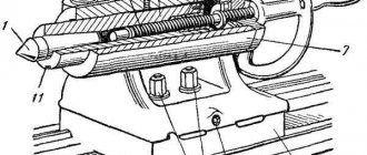
We provide a guarantee of up to 12 months on a number of components. Delivery is carried out throughout Russia and the CIS countries through transport companies. Tailstock. At high cutting speeds, which are used on modern lathes, non-rotating centers, which have sufficient rigidity, become inoperable due to rapid wear of the surfaces of the center recesses and the centers themselves. Plug-in rotating centers have insufficient rigidity. Therefore, on a number of models of lathes, a rotating spindle on rolling bearings is built into the tailstock quill, into the socket of which the center is inserted. This design has high rigidity and allows operation at high speeds.
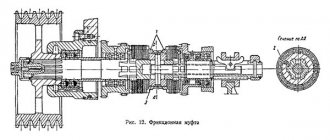
The design of tailstocks in which the quill passes through the body is also common (see figure). In this case, the body 2 has a through bore through which the quill 1 passes. The latter has a screw 5 and a flywheel 10 mounted on the right side. In the middle part the quill has a slot through which a nut 6 passes, secured with screws 7 in the headstock body. When the flywheel rotates, not only the quill moves, but also the screw and the flywheel itself. This design ensures a constant size of the supporting surface of the quill in the headstock body, regardless of its overhang, which creates greater rigidity of the system. The mechanism for securing the headstock to the machine bed is also original. When turning the handle 9, the eccentric 8 lifts up the tie 13 and the bar 17, connected to the tie by a bolt 14 with a spherical washer 15. The bar, through a spherical pin 18, presses the clamp 16 to the frame guides and securely fastens the tailstock. The rolling pin is secured in the headstock body by handle 3 using a roller 11 and a threaded bushing 12. The rear center is squeezed out of the rolling pin with a screw 5 using insert 4. In medium-sized lathes, the tailstock is moved along the bed guides by turning a small gear located in the headstock bracket and interlocking with the machine rack. In heavy machines, to facilitate the movement of the tailstock, compressed air is supplied under its guides. Thermal expansion of workpieces can cause axial overload on the rotating center of the tailstock and machine spindle. To avoid this phenomenon, a number of companies and, in particular, Czechoslovakian and TOZ companies install thermal elongation compensators and devices for determining the actual axial force acting on the center of the tailstock on the tailstocks of lathes.
equips some models of lathes with drilling tailstocks, which, along with the usual purpose, can be successfully used for drilling work. The headstock is equipped with a stepless feed drive that is independent of other machine mechanisms, which also provides the possibility of fast idle movement of the quill. The feed mechanism has an adjustable stop to limit the drilling depth. The highest quill feed force for drill heads of DK model machines is 1800 kg, which makes it possible to drill holes with a diameter of up to 50 mm in medium-hard steel.
sar-snab.ru
Gearbox 1k62
| № | Name | Marking |
| 1 | Bend | 1K62-78-11 |
| 2 | Replacement gear Z=97 | 1K62-78-31 |
| 3 | Replacement gear Z=64 | 1К62-78-33 |
| 4 | Replacement gear Z=40 | 1K62-78-34 |
| 5 | Replacement gear Z=42 | 1K62-78-35 |
| 6 | Replacement gear Z=50 | 1K62-78-36 |
| 7 | Replacement gear Z=60 | 1K62-78-37 |
| 8 | Replacement gear Z=72 | 1K62-78-38 |
| 9 | Replacement gear Z=75 | 1K62-78-39 |
| 10 | Replacement gear Z=96 | 1K62-78-40 |
| 11 | Replacement gear Z=108 | 1K62-78-41 |
| 12 | Replacement gear Z=70 | 1К62-78-42 |
| 13 | Replacement gear Z=72 | 1K62-78-43 |
| 14 | Replacement gear Z=90 | 1K62-78-44 |
| 15 | Replacement gear Z=96 | 1K62-78-45 |