If you are the happy owner of a 1k62 screw-cutting lathe, then we can help you in the following matters:
- Assistance in the selection and identification of components and spare parts for the machine (We provide oral consultation, accept photographs and drawings of the necessary parts);
- Delivery of new and storage of spare parts from our warehouse;
- Manufacturing of new parts;
- Departure for troubleshooting of the machine to your enterprise;
- Overhaul of the machine;
- Selection and sale of modern equipment and tools;
- We send an electronic passport 1k62 free of charge to your email;
- Free delivery to the transport company terminal.
- Free delivery for orders over 50,000 rubles to the transport company terminal in your city.
Additional information about the 1k62 machine. The 1k62 screw-cutting lathe was produced by the Moscow Machine Tool Plant; the machine was discontinued in 1971.
The standard list of spare parts is listed below. Price and availability available upon request.
Brief description of the main components of the 1K62 lathe
Headstock
The headstock serves to communicate to the spindle various rotation speeds when cutting, drilling, threading and drives replaceable tilt gears. The headstock mechanism allows:
- a) cut threads with an increased pitch of 4 and 16 times, the gear ratio between the feed chain and the spindle increases by 8 and 32 times;
- b) cut right-hand and left-hand threads;
- c) cut multi-start threads divided into 2, 3, 4, 5, 6, 10, 12, 15, 20, 30 and 60 starts.
The headstock is installed on the center line in a horizontal plane with two set screws and two locking screws 1 (Fig. 5).
The spindle speed is set by two handles 5 and 9 (see Fig. 3). By turning the handle 9, which, through a mechanism with a lantern gear and the shift fork, moves the gear blocks 17-18, 19-20 and 24-25 (see Fig. 4), the required number of revolutions is selected according to table 6, placed under the handle. By rotating handle 5, which, using a flat copier with a closed curve, a lever mechanism and shift forks, moves gear blocks 9-10 and 11-12-13, the required number of spindle revolutions is set from the range selected by handle 9. When setting a number of revolutions 630 —2000 handle 9 must be tilted forward away from you and then turned to the left. The switching device allows you to obtain 23 different speeds of forward rotation of the spindle and 12 speeds of reverse rotation.
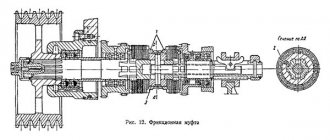
The friction clutch, as well as the main drive band brake, is turned on and off using handles 28 and 37 (Fig. 3). When you turn on the forward rotation of the spindle, one of the handles should be raised up, when you turn on the reverse one, lower it down. When handles 28 and 37 return to the middle position, the band brake is activated.
Gearbox
The feed box mechanism allows, through a lead screw with a pitch of 12 mm (without a pitch increasing link), to obtain the following threads:
- a) metric in increments from 0.87 to 12 mm;
- b) inch from 2 to 24 threads per 1″;
- c) modular from 0.5 to 3 modules;
- d) pitches from 1 to 96 pitches.
Using the mechanism for increasing the pitch, at spindle speeds from 12.5 to 40, it is possible to obtain threads with an increased pitch, 32 times larger than normal, and at speeds from 50 to 160, 8 times in accordance with the data in the table on handle 38 (see Fig. Fig. 3).
Through the running roller, the caliper at any number of spindle revolutions receives longitudinal feeds from 0.07 to 2.08 mm/rev and transverse feeds from 0.035 to 1.04 mm/rev, and at speeds from 50 to 630 per minute - longitudinal feeds from 2 .28 to 4.16 mm/rev and transverse from 1.14 to 2.08 mm/rev.
To cut more precise threads in the feed box, handle position 2 is provided (Fig. 3), in which the lead screw is engaged directly, bypassing the feed box mechanism. In this case, the required pitch is selected using interchangeable gears of a special set.
By turning handle 38, the choice of a number of threads or feeds is determined. To obtain the required value from the selected row of threads or feed, it is necessary to pull the drum disk out of the handle towards you, turn until the marks of the disk coincide with the corresponding column of the drum table, and then move the disk forward to its previous position.
To carry out rapid movements of the caliper, an overrunning clutch is mounted in the feed box on the output shaft.
Apron
The apron has four cam clutches, allowing for forward and reverse movement of the carriage and support. The movements of the carriage and the lower part of the support are controlled by the mnemonic handle 16 (see Fig. 3). The direction in which the handle is turned on coincides with the direction in which the caliper moves. The inclusion of fast movements of the caliper in the indicated four directions is carried out by additionally pressing the button 15, built into the handle 16. This pressing turns on the high-speed electric motor, which, through a V-belt drive, communicates movement to the drive shaft.
The apron has a blocking device that prevents the simultaneous activation of the longitudinal and transverse feeds of the caliper, and the simultaneous activation of the lead screw and the lead roller. as well as a safety cam clutch, which is activated under the influence of forces generated when the apron is overloaded.
To cut a thread, use handle 31 to turn on the lead screw nut and disengage the rack and pinion gear by pulling button 35 toward you.
Feed drive of a lathe, using the example of 1K62
The feed drive of a lathe is designed to provide relative movements of the workpiece and tool in the mode of turning a part or in the mode of installation movements. The purpose of the feed chain of a screw-cutting lathe is to ensure the automatic movement of a cutter mounted on a support relative to a rotating workpiece during turning and threading. The source of movement (initial link) of the feed chain is the spindle, therefore the feed speed in screw-cutting lathes is measured and indicated in millimeters per spindle revolution (mm/rev). mechanism of a lathe must allow: turning the feed on and off without stopping the rotation of the spindle; reversing the feed while maintaining the same direction of spindle rotation; feed reversal simultaneously with spindle reversal; regulation of feed amount; manual movement of the cutter relative to the workpiece.
In the 1K62 lathe (see Drive of the main movement of a lathe-type machine, Fig. 1), the feed chain (shaft VII) receives movement either directly from the spindle (block B6, shifted to the left), or through a search of the main movement chain (block B6 is shifted to the right and its wheel z = 45 is engaged with a gear z = 45 on shaft III). In the latter case, shaft III, depending on the positions of the search blocks B4 and B5, can rotate with a number of revolutions that is 2, 8 or 32 times greater than the number of spindle revolutions. Gearing (blocks) B4 and B5, main movement drives and block B6 are used in this case in the feed chain as a link in increasing the pitch of cut threads or feed values.
The triple sliding block B7, on shaft VIII, is a snaffle, which forms two forward and one reverse gears. It is controlled by handle 3 (see Metal lathe: purpose, layout, parameters, Fig. 2).
When switching blocks B3, B4, B5, B6 and B, shaft VIII can rotate with a number of revolutions equal to the number of revolutions of the spindle, exceed ero by 2, 4, 8, 16 and 32 times, be less by 1.51, 2 or 3, 02 times.
box of the lathe through replaceable gears C1 and C2, (see Drive of the main movement of a lathe, Fig. 1) of the tuning guitar. In the general case, the guitar (Fig. 1) consists of four interchangeable wheels A, B, C, D and a lever 2, which has two grooves - radial 4 and circular 1.
Groove 1 makes it possible to rotate lever 2 around the axis 5 of the shaft and firmly secure it with nut 3. In the radial groove, you can move guitar pin 6, on which the block of replaceable gears B and C rotates freely. Pin 6 is also secured with a nut. Turning the lever and radially moving the guitar finger makes it possible to couple four interchangeable wheels with different numbers of teeth in pairs. In the 1K62 lathe, to obtain longitudinal feed and for cutting metric and inch threads, set C1 = 42 and C2 = 50, and when cutting modular and pitch threads, C1 = 64 and C2 = 97. In both cases, one idler gear z is installed on the guitar finger = 95.
In the feed box of a lathe there are a number of gear couplings, sliding blocks and gears, as well as a Norton cone - a device consisting of a stepped cone of gears mounted on shaft X, with which a block (carriage) of B9 gears sliding along shaft XI can engage. When cutting threads, the feed box transmits rotation to the lead screw XV; When turning and cutting face (flat) threads, the running roller XVI rotates. Using a lead roller for feed during turning allows you to maintain the accuracy of the lead screw longer, which is necessary when cutting threads.
Kinematic diagram of the 1V62G machine
The kinematics of the 1V62G screw-cutting lathe makes it possible to set into motion both the main drive (spindle rotation, support feed) and auxiliary ones: accelerated support approach, speed reverse, and others. Spindle rotation is achieved by V-belt transmission from motor 1 through pulleys 2 and 3 to the spindle pulley, then the spindle rotates through the gearbox gears. The caliper moves through shaft 12 from the feed box and is synchronously connected to the gearbox through a series of gears and intermediate shafts.
Kinematic diagram of the 16v20 machine
In the left cabinet of the bed there is an oil reservoir in which an oil pump is built in to supply oil to the machine components. The right cabinet contains a pump for water, which drains and collects in the lower niche of the machine. It also serves as the basis for installing the bed. The engine for transmitting the accelerated movement of the caliper is mounted on the side of it using brackets. The caliper moves through the running shaft 5 and screw 4, and they are covered with casings 1 and 14. When processing parts above the cavity, it is possible to move the upper carriage in the desired direction. Before you start processing a workpiece with a diameter of 445 mm, you need to remove the protective bridge (22). It is mounted on the frame guides with countersunk bolts (23) and pins (24).
When installing the adapter strip in place, you need to tighten the bolts carefully, crosswise, so that there is no distortion. Under the guide there is a rail assembled from parts, and through it the caliper moves during operation.
Under the guide there is a rail assembled from parts, and through it the caliper moves during operation.
Such machines are used in industrial and agricultural enterprises, and also, due to their relatively low weight (2430 kg), in repair shops.
Electrical circuit of the machine 1V62g
Spindle 1K62D 1K62D.020.224
Spindle assembly for screw-cutting lathe 1K62D 1K62D.020.224. You can also purchase spindle bearings 1K62D.020.224.
Spindle is the shaft of a metal-cutting machine that transmits rotation to the tool fixed in it or the workpiece being processed. The choice of spindle material is very important. Medium-load spindles are usually made from steel 45 with improvement (hardening and high tempering). For increased power loads, 45 steel with low tempering is used. For spindles requiring high surface hardness and a tough core, steel 45 with high-frequency hardening and low tempering is used. For increased requirements, steels 40Х, 38ХМУА (high-speed machine tool spindles), 20Х with carburization, hardening and tempering, 12ХНЗ (high-speed and heavily loaded spindles) and other low-alloy steels are used. Steel 65G is used for large spindles.
The structural shape of the spindles depends on the method of fastening the clamping devices or tools on it, the fit of the drive elements and the types of supports used. Spindles, as a rule, are made hollow for the passage of the rod, as well as to reduce weight. The front ends of the spindles of general purpose machine tools are standardized.
Supports. Rolling and sliding bearings are used as supports for machine tool spindles. Since spindles require high precision, the rolling bearings used in spindle supports must be of high accuracy classes. The choice of bearing accuracy class is determined by the runout tolerance of the front end of the spindle, which depends on the required processing accuracy. Usually, more precise bearings are used in the front support than in the rear one.
The design of spindle units is very diverse. In Fig. Figure 2.12 shows the spindle assembly of a screw-cutting lathe with a double-row roller bearing with a tapered hole in the inner ring as a front support. When the inner ring of the bearing moves axially, the conical neck of the spindle deforms the ring, and its diameter increases. This eliminates the radial gaps between the rollers and rings and creates a preload.
Preload is carried out in various ways. In angular contact ball bearings and tapered roller bearings, when installed in pairs, the preload is obtained by adjustment during assembly, and in radial ball bearings, by shifting the inner rings relative to the outer ones. In Fig. Figure 2.13 presents constructive methods for creating preload of ball bearings by grinding the ends of the inner rings (Fig. 2.13, a), installing spacers between the rings (Fig. 2.13, b), and using springs that ensure constant preload (Fig. 2.13, c). In Fig. 2.13, d shows a method for creating preload due to deformation of the inner ring when installing it on the conical neck of the spindle in roller bearings with cylindrical rollers. Sliding bearings used as spindle supports can be unregulated (they are rarely used, with almost complete absence of wear over a long service life), with radial, axial clearance adjustment, hydrostatic (they provide for the supply of oil under pressure into several pockets, from which it is forced out through the gap between the spindle journal and the bearing), hydrodynamic and gas-lubricated.
Precision machines use hydrostatic bearings, which create high precision spindle rotation. Their load-bearing capacity, rigidity and accuracy depend on the size of the gaps, pressure, and support pattern. In Fig. Figure 2.14 schematically shows the design of a hydrostatic support. Oil under pressure is supplied to pockets 1 through holes 2. During rotation, oil is forced out of these pockets through the gap between the journal and the bearing and from hole 3 into the reservoir. As the external force increases, tending to reduce the gap, the oil pressure in the reservoir increases and the gap is restored. Hydrostatic bearings stabilize the friction mode with the lubricant at the lowest rotation speeds.
A self-aligning hydrodynamic plain bearing used in grinding machines is shown in Fig. 2.15. In the holder 4 there are five self-aligning liners 5. Each liner has one spherical support in the form of a pin 3. The pins are secured in the holder with screws 2 and 8 with washers 1 passing through the cover 7. O-rings 6 are provided between the cover and the holder.
The inserts are self-aligned by spherical supports in the direction of rotation of the spindle and in the direction of its axis. This creates reliable friction conditions with the lubricant in the support and stable oil wedges, and also avoids edge pressures caused by misalignment of the working surfaces, elastic or thermal deformations of the spindle. The design of the bearings ensures high precision of spindle rotation due to its centering by hydrodynamic pressures that arise in several zones around the circumference.
Spindle bearings must be reliably protected from contamination and lubricant leakage. Lip seals (Fig. 2.16, a) made of leather, plastic or oil-resistant rubber are placed in a metal casing and pressed against the shaft with a bracelet spring. In machine spindles, it is more advisable to use labyrinth seals (Fig. 2.16, b), which do not have rubbing surfaces and can operate at high rotation speeds. They provide bearing protection by resisting fluid flow through narrow slots. In Fig. 2.16, c shows seals for vertical shafts, seals with piston-type rings and a combined felt seal with a baffle ring that rejects oil.
Rules of operation and care
There are rules for caring for the unit so that it does not break down and is always ready for use. The equipment must be regularly inspected and checked for damage.
Engine operation is determined by sound. After starting, listen. If there are no extraneous sounds, oil is supplied, then the engine is working. If there are extraneous sounds, you need to disassemble the mechanism and find out the reason.
Care must be taken to ensure that the safety shield is holding the workpiece. Even if there is a minor malfunction, you must stop working and take the parts for repair.
From time to time, clean pipes and equipment, change cutters so that the load on the engine is less.
Design and operating characteristics of the main components of the machine
General view and layout of the 1K62 machine (Fig. 1)
The main components of the machine: bed 13, which serves to connect all components of the machine; headstock 2, which houses the spindle 4 of the machine and the gearbox; a support 11 on which the cutting tool is fixed; tailstock 15; feed box 3, transmitting rotation to the lead shaft 24 and the lead screw 23; cabinet 20 with electrical equipment of the machine; stands 22 and 29.
The machine bed 13 (see Fig. 1, a) rests on the left 29 and right 22 pedestals, to which it is rigidly fastened. The left cabinet contains the electric motor of the main drive of the machine. The right cabinet contains a pump that supplies coolant through a hose to the cutting tool. Liquid flows from trough 27 into the internal cavity of the cabinet. The most accurate position of the moving units of the machine is ensured by the combined frame guides - prismatic a and flat b (Fig. 1, b).
Headstock 2 is bolted to the left side of the frame. The inner part of the headstock contains a spindle 4 and a gearbox, covered with a lid on top.
If necessary, a rod processed on the machine can be passed through the through hole of spindle 4, and the front center can be installed in the conical socket of the spindle. At the right protruding end of the spindle there is a centering belt, a shoulder and a thread for precise alignment and fastening of the faceplate with chuck 5, into the cams of which the workpieces are installed.
The support 11 is designed to move the cutting tools attached to it and consists of the following main parts: a carriage 6, an apron 25, a transverse slide 7, a middle rotating part 8, an upper slide 10 and a quadruple tool holder 9 for installing and securing cutting tools.
Carriage 6 moves in the longitudinal direction along prismatic a and flat b guides (Fig. 1, b). Planks 1 and 2 of the carriage slide along the lower guides d and c. The carriage is moved manually in the longitudinal direction by rotating the flywheel 26 (Fig. 1, a).
The apron 25 is rigidly fixed to the carriage 6. It contains mechanisms that convert the rotational movement of the roller 24 and the screw 23 into the translational movement of the caliper.
To eliminate backlash in the screw drive, the screw nut consists of two parts, which are moved apart with a wedge. The middle part 8, together with the guides of the upper slide 10 located on it, which can be rotated relative to the axis of the machine at an angle and mounted on the transverse slide 7, is intended for processing conical surfaces of products.
The upper slide 10 is designed to move the cutter manually when rotating the handle 12. The exact amount of movement of the caliper is manually measured using dials with a division value of 0.05 mm
Feed box 3 serves to transmit rotation to the lead roller 24 or lead screw 23. The feed box is connected to the machine spindle by a transmission, which includes a set of interchangeable wheels located under the shield 1.
The tailstock 15 is designed to support the workpieces being processed with its rear center or to install and move axial tools. The main parts of the tailstock: plate 17, body 16, quill 14, clamping bar 1 (Fig. 1, c).
The tailstock moves along prismatic a and flat b guides (Fig. 1, c) of the machine bed. The movement is carried out either manually or using a caliper - if the tailstock is connected to it with a lock (Fig. 1, d). The lock consists of a bar 2 attached to the cross slide 1, a caliper and a bar 4 connected to the tailstock plate 3. By bringing the caliper to the tailstock and moving the slide 1 in the transverse direction, the protrusion of the bar 2 is inserted behind the protrusion of the bar 4. In this case, the tailstock is connected to the caliper and together with it will move in the longitudinal direction from the feed mechanism.
In order for the top of the rear center to be accurately located on the axis of the machine, the body 16 (Fig. 1, a) is moved in the transverse direction relative to the plate 17. To process conical surfaces of parts, the rear center is shifted with a screw 19 from the axis of the machine in the direction “toward” or "Push". Quill 14 has a tapered hole for mounting rear center or axial tools.
The electrical equipment of the machine is located in cabinet 20. On the front wall of the cabinet there is a panel 18 with an ammeter indicating the current of the main electric motor of the machine, and switches that turn on the machine to the electrical network, machine lighting and the electric motor of the pump supplying coolant.
Under cover 21 there is an electric motor for rapid movement of the caliper.
Causes of turning errors on a 1K62 screw-cutting lathe
The following factors can affect the accuracy and purity of processing:
- Incorrect level installation of the machine on the foundation;
- The presence of a gap between the carriage clamping strips and the bed; the presence of a gap between the guides and wedges (it is necessary to tighten the clamping bars and wedges);
- Non-rigid spring mounting of the cutter;
- The part fixed in the chuck has a large overhang (it should be supported by a steady rest or pressed in with the center);
- The chuck faceplate is poorly secured, the chuck mounting screws are not tightened enough;
- Presence of dirt in the conical hole of the spindle;
- The mass of the chuck or workpiece is unbalanced (needs to be balanced);
- Incorrect cutting modes selected (high cutting speed or feed);
- The spindle bearings are not adjusted correctly. (for adjustments, see section “Adjusting the Machine,” page 43).
General design and operating principle
The design features regulatory bodies that are familiar to experts, and a simple control scheme is used. The model consists of nodes:
- bed;
- front, rear cabinets;
- headstock;
- chuck;
- tailstock;
- tool holder;
- apron with caliper feed mechanics;
- drive shaft;
- gearbox.
The design is designed for high vibration resistance and rigidity. The base is pedestals, and to increase their rigidity, vertical ribs are used on the walls.
On the left side of the unit there is a headstock, inside it is a gearbox, a spindle with a chuck. On the right side is the tailstock. The caliper can move in different directions due to the apron.
Installation procedure
Before installing it, you should carefully check the condition of the surfaces of the spindle and chuck. Surfaces should not have nicks, scratches, burrs or contaminated areas.
Identified defects are eliminated point by point with a file or scraper. You should check the runout of the end and cone of the spindle landing base, which should not exceed three microns.
Place a metal rod or pipe with a diameter of about 20 mm into it. clasp it with your fists. With a partner, grasp the rod on both sides, or using lifting mechanisms, through the mounting loop, move the cartridge onto the mounting stand fixed to the machine support.
Install the guide in the tailstock. The chuck should be shifted by rolling towards the spindle axis.
Using a longitudinal feed, move it to the spindle flange so that the chuck studs do not reach the mounting holes of about 10 mm. The machine should be set to neutral speed to allow the spindle to rotate freely.
Move the tailstock with the quill completely retracted forward towards the chuck so that the guide extends over the entire width of the cam prisms and fix the tailstock.
Read also: Is it possible to fill the compressor with engine oil?
Clamp the jaws of the chuck to transfer the weight to the guide. Align the key on the spindle flange with the mounting hole. Set the rotary washer to the position of the open holes. Using the quill, push the cartridge forward until it stops.
After making sure that all the stud nuts are out of the back of the spindle flange, turn the rotary washer to the locked position. Tighten the top nut with enough force to transfer the weight of the chuck onto the spindle. Open the cams and move the tailstock back. Compress the nuts according to the rule crosswise, evenly distributing the force between the studs.
After installation is completed, the chuck should be checked for axial and axial runout. If the standards are exceeded, it should be removed and all mating parts of this assembly should be carefully inspected.
Video: installation of a lightweight cartridge on a threaded fastener.
Design Features
The design features of 1K62 include the versatility of its functionality and well-organized workspace. The ease of setting up the operating modes of the machine is especially noted.
The increased rigidity of all its working units is ensured by the use of heavy-duty bearings in the design. Due to the significant drive power on the 1K62, it is possible to process workpieces that have undergone long-term hardening.
Please note: The design of the bed provides the ability to change the position of the rear beam, allowing you to grind cone-shaped parts. The beam itself is connected to the lower plane of the caliper with a special lock, which expands the range of drilling operations
The main structural components of this product include:
The beam itself is connected to the lower plane of the support with a special lock, which expands the range of drilling operations. The main structural components of this product include:
- A bed with two cabinets located at the edges.
- Two headstocks (front and rear placement).
- Caliper with tool holder and apron mechanism.
- Gearbox (Gearbox).
Let us next consider the organization of the workplace.
Workspace dimensions
The characteristics of the 1K62 workplace are as follows:
- the height of the frame with superstructures is one and a half meters;
- the total length of the base is from 2.5 to 3.5 meters (with a width of 1.2 meters);
- the permissible size of the part placed above the support is up to 22.4 cm, and above the bed - up to 43.5 cm
- permissible incisal section - within 2.5 cm;
- the maximum size of the blank fixed during processing is within the range from 75 cm to 150 cm;
- through size (diameter) of the shaft – 5.5 cm;
- free movement of the working carriage – up to 1330 mm.
Under certain operating conditions of machine tool equipment (when fixing a workpiece in a chuck, in particular), the weight of the processed blank can reach 300 kg. When installing workpieces in a centered position, its weight can reach 1300 kg.
Headstock and tailstock
The main purpose of the headstock is to provide the specified parameters for shaft rotation in various operating modes when performing the entire range of work operations. Switching elements for replaceable gearbox gears are also located here. The mechanisms located in it allow:
- make threads with a pitch that is a multiple of 4 and 16 units; in this case, the gear ratio increases by 8 and 32 times, respectively;
- provide right and left cutting;
- prepare threads in multi-start mode (from 2 to 60 starts).
Technical data and characteristics of the screw-cutting lathe 1K62
| Parameter name | DIP-200 (1d62m) | 1A62 | 1K62 | 16K20 |
| Main settings | ||||
| Accuracy class according to GOST 8-82 | N | N | N | N |
| The largest diameter of the workpiece processed above the bed, mm | 410 | 400 | 400 | 400 |
| The largest diameter of the workpiece processed above the support, mm | 210 | 210 | 220 | 220 |
| Maximum length of workpiece processed in centers (RMC), mm | 750, 1000, 1500 | 750, 1000, 1500 | 710, 1000, 1400 | 710, 1000, 1400, 2000 |
| Maximum turning length, mm | 650, 900, 1400 | 650, 900, 1400 | 640, 930, 1330 | 645, 935, 1335, 1935 |
| Height of the center axis above the flat guides of the frame, mm | 202 | 215 | 215 | |
| The greatest distance from the axis of the centers to the edge of the tool holder, mm | 228 | 228 | 240 | |
| Height from the supporting surface of the cutter to the axis of the centers (cutter height), mm | 23 | 25 | 25 | 25 |
| The largest cross-section of the cutter holder, mm | 25 x 25 | 25 x 25 | 25 x 25 | 25 x 25 |
| Maximum mass of workpiece processed in the chuck, kg | 500 | 200 | ||
| Maximum mass of workpiece processed in centers, kg | 1500 | 460, 650, 900, 1300 | ||
| Spindle | ||||
| Diameter of through hole in spindle, mm | 38 | 36 | 38/ 47 | 52 |
| The largest diameter of the rod passing through the hole in the spindle, mm | 37 | 34 | 36/ 45 | 50 |
| Number of speed steps for direct spindle rotation | 18 | 21 | 24 | 24 |
| Spindle rotation speed in forward direction, rpm | 11,5..600 | 11,5..1200 | 12,5..2000 | 12,5..1600 |
| Number of spindle reverse rotation frequency steps | 9 | 12 | 12 | 12 |
| Spindle rotation speed in reverse direction, rpm | 18..760 | 18..1520 | 19..2420 | 19..1900 |
| Size of the internal cone in the spindle, M | Morse 5 | Morse 5 | Morse 5/6 | Morse 6 |
| Spindle end flanged | M90x6 | M90x6 | M90x6/ 6 | 6K according to GOST 12593-72 |
| Spindle braking | There is | There is | There is | |
| Spindle material | Art.45 | Art.45 | ||
| Caliper. Submissions | ||||
| Maximum movement of the longitudinal carriage of the caliper by hand, mm | 650, 900, 1400 | 650, 900, 1400 | 640, 930, 1330 | |
| Maximum movement of the longitudinal carriage of the caliper along the roller and along the screw, mm | 650, 900, 1400 | 650, 900, 1400 | 640, 930, 1330 | 645, 935, 1335, 1935 |
| Maximum movement of the transverse carriage of the caliper by hand, mm | 280 | 280 | 250 | 300 |
| Maximum movement of the transverse carriage of the caliper along the roller and along the screw, mm | 280 | 280 | 250 | |
| Longitudinal movement per dial division, mm | No | 1 | 1 | 1 |
| Transverse movement per dial division, mm | 0,05 | 0,05 | 0,05 | 0,05 |
| Transverse movement per one revolution of the dial (transverse caliper screw pitch), mm | 5 | 5 | ||
| Number of longitudinal feed stages | 35 | 35 | 49 | |
| Limits of longitudinal working feeds, mm/rev | 0,082..1,59 | 0,082..1,59 | 0,07..4,16 | 0,05..2,8 |
| Number of cross feed stages | 35 | 35 | 49 | |
| Limits of working cross feeds, mm/rev | 0,027..0,522 | 0,027..0,522 | 0,035..2,08 | 0,025..1,4 |
| Speed of fast movements of the caliper, longitudinal, m/min | No | No | 3,4 | 3,8 |
| Speed of fast movements of the caliper, transverse, m/min | No | No | 1,7 | 1,9 |
| Maximum permissible speed when working on stops, m/min | 0,25 | |||
| Number of metric threads to be cut | 25 | 19 | 44 | |
| Limits of metric thread pitches, mm | 1..12 | 1..12 | 1..192 | 0,5..112 |
| Number of inch threads to be cut | 30 | 20 | 38 | |
| Limits of pitches of inch threads, threads/inch | 24..2 | 24..2 | 24..2 | 56..0,5 |
| Number of modular threads to be cut | 12 | 10 | 20 | |
| Limits of modular thread pitches, module | 0,25..3 | 0,5..3 | 0,5..48 | 0,5..112 |
| Number of cut pitch threads | 24 | 24 | 37 | |
| Limits of pitches of cut pitch threads | 96..7 | 95..7 | 96..1 | 56..0,5 |
| Longitudinal switch stops | There is | There is | There is | There is |
| Transverse switching stops | No | No | No | |
| Overload protection | There is | There is | There is | There is |
| Blocking the simultaneous activation of longitudinal and transverse movement of the caliper | There is | There is | There is | There is |
| Thread indicator | No | |||
| Outer diameter of lead screw, mm | 40 | 40 | ||
| Lead screw pitch, mm | 12 | 12 | ||
| Running shaft diameter, mm | 30 | 30 | ||
| Cutting slide | ||||
| Maximum movement of the cutting slide, mm | 100 | 113 | 140 | 150 |
| Movement of the cutting slide by one division of the dial, mm | 0,05 | 0,05 | 0,05 | 0,05 |
| Movement of the cutting slide per one revolution of the dial (screw pitch of the cutting slide), mm | 5 | 5 | ||
| Maximum angle of rotation of the cutting slide, degrees | ±45° | ±90° | ±90° | ±90° |
| Scale division of the tool slide rotation scale, deg | 1° | 1° | 1° | 1° |
| Number of cutters in the cutting head | 4 | 4 | 4 | 4 |
| Tailstock | ||||
| Tailstock quill diameter, mm | 65 | 70 | ||
| Cone of the hole in the tailstock quill according to GOST 2847-67 | Morse 4 | Morse 4 | Morse 5 | Morse 5 |
| Maximum movement of the quill, mm | 150 | 150 | 150 | 150 |
| Movement of the quill by one division of the dial, mm | No | No | 0,05 | 0,1 |
| The amount of lateral displacement of the headstock body, mm | ±15 | ±15 | ±15 | ±15 |
| Electrical equipment | ||||
| Number of electric motors on the machine | 1 | 2 | 4 | 4 |
| Main drive electric motor, kW | 4,3 | 7 | 10 | 11 |
| Electric motor for fast movements, kW | No | No | 0,8 | 0,75 |
| Electric motor of hydraulic station, kW | No | No | 1,1 | 1,1 |
| Cooling pump electric motor, kW | No | 0,125 | 0,125 | 0,12 |
| Cooling pump (pump) | PA-22 | PA-22 | PA-22 | |
| Dimensions and weight of the machine | ||||
| Machine dimensions (length width height) (RMC = 1000), mm | 2650 x 1315 x 1220 | 2650 x 1580 x 1210 | 2812 x 1166 x 1324 | 2795 x 1190 x 1500 |
| Machine weight (RMC = 1000), kg | 1750 | 2105 | 2140 | 3005 |
Machine diagram 1A62. Screw-cutting lathe. Kinematic
A kinematic diagram is a graphical diagram of the display of working units and blocks of a structure mechanism. The basic kinematic diagram shows the sequence of transmission of motion from the engine through the intermediate mechanism to the working parts of the product and their relationship. Kinematic diagrams specifically depict only those elements of the assembly structure that take part in the transmission of motion, these include intermediate gears, running rods and clamps, shafts, drive pulleys, couplings, etc. The design of any assembly mechanism that has moving parts is drawn in in the form of graphics on the diagram with solid lines alternating with dotted lines, respectively marking each element with numbers and subsequent decoding. There are spatial kinematic diagrams of mechanisms, which are usually depicted in the form of expanded diagrams. They are obtained by combining all axes in one plane and then projecting them onto the plane. Such diagrams make it possible to understand the sequence of motion transmission. On a kinematic diagram it is possible to display individual elements of other types of circuits that directly affect its operation, for example, electrical ones. The kinematic diagram begins to be read from the engine, which is the source of movement of all parts of the mechanism. By installing each element of the kinematic chain shown in the diagram sequentially according to the symbols, its purpose and the nature of the transmission of motion are revealed.
Machine device
The front of the lathe, shaped like a cabinet, is actually the gearbox. On the top surface of the cabinet there is a peephole for checking the oil. If oil flows like a fountain during operation, it means that the pump is working correctly and provides lubrication to the rubbing parts.
On the front panel of the headstock there are two gear shift levers, which are located at the edges. The right lever lowers the spindle speed and has four positions: optimal speed for turning. high speed for finishing cylindrical surfaces. Intermediate position for cutting threads with a cutter or die. The left gearshift lever has six positions, respectively, six speeds.
Between the speed shift levers there are two other levers for setting the thread cutting operation. The design of the machine allows you to cut right-handed and left-handed threads.
At the bottom of the headstock there is a feed box equipped with two levers. The lever on the left switches the feed and thread type. Located on the right, it is used to adjust the feed of the caliper depending on the depth of cut and the hardness of the material being processed. The K-62 machine is equipped with two motors: main and rapid feed. The front apron is equipped with two flywheels:
- one for feeding along the bed;
- the second is for serving across.
Main nodes
The rotating spindle of the 1k62 screw-cutting lathe ensures surface treatment of cylindrical and conical workpieces.
The caliper performs the longitudinal and transverse movement of the tool holder with the cutter for removing chips, cutting threads, facing or cutting off the workpiece. The installed feed mechanism drive is used to configure thread cutting modes. By means of the screw-nut transmission, the lateral movement of the tool holder is carried out.
The machine control levers are installed on the headstock. To change cutting modes, a mechanism for switching spindle rotation speeds is installed. The direction of movement will be changed by a special friction clutch and a reversing mechanism.
The apron is used to change the feed modes, and for control there are levers on the headstock. The apron mechanism feeds the caliper during turning and threading.
The main parameter that determines the size of a lathe is the height from the plane of the bed to the axis of rotation of the spindle. This height is half the largest diameter of the part that can be machined above the bed. The largest diameter of the product above the bed and the distance between the chuck and the tailstock quill determine its capabilities and are included in the main technical characteristics of the 1k62 machine. Before work, the turner checks the dimensions of the workpiece according to the given characteristics.
The machine is equipped with an additional electric motor with a power of one kilowatt for accelerated movement of the support carriage; it is turned on by pressing a special button located at the end of the control lever. During drilling work, you can mechanically feed the tailstock with a drill by attaching it to the support.
Specifications
The weight of the K62 lathe is 2.5 tons.
Dimensions:
- length - 2500 millimeters;
- width - 1200 millimeters;
- height - 1500 millimeters.
The maximum diameter of the workpiece above the machine support is 224 millimeters. The workpiece for processing is no more than 1500 millimeters in length. Spindle speed 2420 rpm.
A screw-cutting lathe is a complex technological machine with 24 spindle rotation speeds and 48 support feeds. The controls are located on the front panels of the gearboxes and feeds.
To set a given spindle rotation speed, you must first disable the clutch and turn off the electric motor, and then move the handle to set the required frequency range (for example, 630...2000, 50...160). The gear shift knob should be moved smoothly, without jerking, ensuring that it is fixed in each of the four positions, setting the specified spindle speed (for example, 630 rpm).
Spindle 1K62 1K62-02-130
Spindle assembly for screw-cutting lathe 1K62 1K62-02-130 . You can also purchase spindle bearings 1K62-02-130.
Spindle is the shaft of a metal-cutting machine that transmits rotation to the tool fixed in it or the workpiece being processed. The choice of spindle material is very important. Medium-load spindles are usually made from steel 45 with improvement (hardening and high tempering). For increased power loads, 45 steel with low tempering is used. For spindles requiring high surface hardness and a tough core, steel 45 with high-frequency hardening and low tempering is used. For increased requirements, steels 40Х, 38ХМУА (high-speed machine tool spindles), 20Х with carburization, hardening and tempering, 12ХНЗ (high-speed and heavily loaded spindles) and other low-alloy steels are used. Steel 65G is used for large spindles.
The structural shape of the spindles depends on the method of fastening the clamping devices or tools on it, the fit of the drive elements and the types of supports used. Spindles, as a rule, are made hollow for the passage of the rod, as well as to reduce weight. The front ends of the spindles of general purpose machine tools are standardized.
Supports. Rolling and sliding bearings are used as supports for machine tool spindles. Since spindles require high precision, the rolling bearings used in spindle supports must be of high accuracy classes. The choice of bearing accuracy class is determined by the runout tolerance of the front end of the spindle, which depends on the required processing accuracy. Usually, more precise bearings are used in the front support than in the rear one.
The design of spindle units is very diverse. In Fig. Figure 2.12 shows the spindle assembly of a screw-cutting lathe with a double-row roller bearing with a tapered hole in the inner ring as a front support. When the inner ring of the bearing moves axially, the conical neck of the spindle deforms the ring, and its diameter increases. This eliminates the radial gaps between the rollers and rings and creates a preload.
Preload is carried out in various ways. In angular contact ball bearings and tapered roller bearings, when installed in pairs, the preload is obtained by adjustment during assembly, and in radial ball bearings, by shifting the inner rings relative to the outer ones. In Fig. Figure 2.13 presents constructive methods for creating preload of ball bearings by grinding the ends of the inner rings (Fig. 2.13, a), installing spacers between the rings (Fig. 2.13, b), and using springs that ensure constant preload (Fig. 2.13, c). In Fig. 2.13, d shows a method for creating preload due to deformation of the inner ring when installing it on the conical neck of the spindle in roller bearings with cylindrical rollers. Sliding bearings used as spindle supports can be unregulated (they are rarely used, with almost complete absence of wear over a long service life), with radial, axial clearance adjustment, hydrostatic (they provide for the supply of oil under pressure into several pockets, from which it is forced out through the gap between the spindle journal and the bearing), hydrodynamic and gas-lubricated.
Precision machines use hydrostatic bearings, which create high precision spindle rotation. Their load-bearing capacity, rigidity and accuracy depend on the size of the gaps, pressure, and support pattern. In Fig. Figure 2.14 schematically shows the design of a hydrostatic support. Oil under pressure is supplied to pockets 1 through holes 2. During rotation, oil is forced out of these pockets through the gap between the journal and the bearing and from hole 3 into the reservoir. As the external force increases, tending to reduce the gap, the oil pressure in the reservoir increases and the gap is restored. Hydrostatic bearings stabilize the friction mode with the lubricant at the lowest rotation speeds.
A self-aligning hydrodynamic plain bearing used in grinding machines is shown in Fig. 2.15. In the holder 4 there are five self-aligning liners 5. Each liner has one spherical support in the form of a pin 3. The pins are secured in the holder with screws 2 and 8 with washers 1 passing through the cover 7. O-rings 6 are provided between the cover and the holder.
The inserts are self-aligned by spherical supports in the direction of rotation of the spindle and in the direction of its axis. This creates reliable friction conditions with the lubricant in the support and stable oil wedges, and also avoids edge pressures caused by misalignment of the working surfaces, elastic or thermal deformations of the spindle. The design of the bearings ensures high precision of spindle rotation due to its centering by hydrodynamic pressures that arise in several zones around the circumference.
Spindle bearings must be reliably protected from contamination and lubricant leakage. Lip seals (Fig. 2.16, a) made of leather, plastic or oil-resistant rubber are placed in a metal casing and pressed against the shaft with a bracelet spring. In machine spindles, it is more advisable to use labyrinth seals (Fig. 2.16, b), which do not have rubbing surfaces and can operate at high rotation speeds. They provide bearing protection by resisting fluid flow through narrow slots. In Fig. 2.16, c shows seals for vertical shafts, seals with piston-type rings and a combined felt seal with a baffle ring that rejects oil.
Advantages of the unit
Despite its long history, the unit we are considering is still common in metalworking plants and repair shops. The undoubted advantages of the model are due to the following criteria.
- The components and structural parts of the equipment have increased strength and increased rigidity, as well as special support parts, which allows you to work with hardened material.
- The special design of the machine allows it to better withstand vibrations during the manufacturing process of parts.
- The factory equipment includes replacement gears for advanced customization of the headstock guitar to increase the range of threads that can be cut.
- A well-thought-out power supply system for the machine, including several thermal relays and fuses to protect against short circuits and overloads.
- The presence of special support elements that compensate for excessive dynamic loads. Thanks to this, it becomes possible to produce parts with increased precision.
- Possibility of transversely shifting the tailstock by 15 mm in forward and reverse directions for turning flat cones.
- Wide range of adjustment of spindle speeds and working feeds.
- One of the main advantages of the 1K62 screw-cutting lathe and its technical characteristics is the ease and simplicity of setting operating modes, which undoubtedly makes it easier to control the machine in the production process and relieves the worker of unnecessary physical stress.
- Availability of additional equipment and accessories, included with the machine or purchased separately. It significantly expands the working functionality.
Despite the long-discontinued production of machines of this model, improved versions of machines manufactured on the basis of 1K62 continue to be produced. The wide capabilities, versatility, ease of maintenance and control of modern mechanisms are developed based on many years of experience in using the 1K62 machine in various conditions. Until now, it remains one of the best metalworking machines.
Adjusting the bearing supports of the spindle of a screw-cutting lathe 1K62
Supports for the front and rear ends of the spindle of the machine 1K62
When repairing, adjust the bearings as follows:
The front spindle bearing is adjusted by nut 11 (Fig. 18), located inside the headstock housing, in the following order: release screw 4 and turn the nut in the required direction. By turning this nut, axial movement of the inner ring of the bearing 10 on the conical neck of the spindle 9 is carried out.
When the nut is turned to the right, the inner ring of the bearing is tensioned onto the conical journal of the spindle. In this case, the ring is deformed, its outer diameter increases, ensuring a tight fit of all rollers to the surface of the inner and outer rings of the bearing, which reduces the radial clearance in the bearing. After adjustment, tighten screw 4 again.
The radial thrust bearings of the rear spindle support are adjusted outside the headstock housing with nut 13 through thermal compensator 1. The tension regulates the axial clearance and is carried out by turning the nut to the right at an angle of 18-20° before the gaps are selected at the joints between the bearings and spacers. The outer rings are installed close to the stop using nut 3.
Spindle of screw-cutting lathe 1K62
Technical characteristics of bearing 3182120
You can buy factory bearings, the long-term performance of which is guaranteed by the manufacturer, with minimal trade margins from official representatives of EPK (the estimated price is about 6,500 rubles, and the accuracy class does not affect it much), illiquid products and bearings from storage can be purchased from companies located in major industrial centers of the past.
Imported bearings of this size are designated NN3020K (the presence of the letter K in the number is mandatory, as it indicates a tapered fit). In Russia, the most common products are from the following manufacturers: FAG, SKF, NACHI, IBC. Just like domestic bearings, imported ones are also widely sold as non-liquid items, primarily these are products of Eastern European manufacturers - URB (Romania) and FLT (Poland), produced and imported into the country during the existence of the Union. Chinese bearings CX, SZPK, ZWZ and others can also be sold under the guise of imported ones.
Dimensions and characteristics of bearing 3182120 (NN3020K)
Bearing diagram 3182120
Photo of bearing 3182120
Technical characteristics of bearing 46215
Bearing 46215 single-row angular contact ball bearing, one-piece, with a bevel on the outer ring GOST 7634-56.
The bearing is a single-row angular contact ball bearing with a contact angle of 26°. This angle is nothing more than the angle between the straight line passing through the center of the ball and the point of contact with the raceway. As the name of this type suggests, the acting loads are both radial and axial. A pair of such bearings ground to each other in a “tandem” arrangement is supplied as a set and has the number 446215.
This type is produced in Samara at SPZ-4. However, higher quality and more expensive angular contact bearings are produced by Saratov (formerly 3 GPZ). Its product range includes several modifications of this type: T-46215E5, 4-46215E5, 6-46215E5, 46215E5, T-46215L, 4-46215L, 6-46215L (they differ in the degree of accuracy and separator material). If they offer you 1 GPZ, then rest assured: these are old bearings, the quality of which can be unpredictable.
Dimensions and characteristics of bearing 46215 (7215A):
Bearing diagram 46215 (7215)
Photo of bearing 46215 (7215)
Russian marking system for rolling bearings. Main and additional digital designation:
Bearing symbols
Explanation of the digital designation of bearing No. 4-3182120:
The decoding of the designation should always start from the right edge of the marking:
— designation of the series of diameters of the outer ring together with the seventh character (3000100), indicating the series of widths (heights), determines the dimensional series (dimension) of the bearing, GOST 3478
— design of the bearing in accordance with GOST 3395. In our case: (182000) Radial roller bearing with short cylindrical, double-row with a tapered hole 1:12, with flanges on the inner ring, GOST 7634
— Designation of the width series (3000100). Together with the third character, indicating a series of diameters, it determines the dimensional series (dimension) of the bearing.
Simplified table of bearing accuracy classes
The modern bearing marking system (GOST 520-2002), adopted in our country, distinguishes the following accuracy classes (in order of decreasing tolerances and increasing accuracy):
8, 7, 0, normal, 6X, 6, 5, 4, T, 2
Bearings of higher accuracy classes 4, T, and 2 can cost several times more than lower classes - 5, 6, 0.
Electrical equipment of the machine
Electrical diagram of the machine
Connection for further operation of the 1K62 machine is made to a three-phase power supply. A grounded or insulated neutral wire is required.
To operate the machine, a power circuit of 380 V, 50 Hz is required. In special cases, the electrical circuit can be adapted for connection to a standard 220 V network. The operation of the control circuit occurs due to the supply of 110 V electricity. The lighting unit operates from a 36/24 V network.
The operation of the equipment is carried out by 4 electric motors. The main power is 10 kW. For fast movements, a 0.8 kW power unit is used. The hydraulic station operates from a 1.1 kW electric motor. Also in the electrical circuit there is a 0.125 kW cooling pump.
In addition, the design of the 1K62 machine contains the following electrical components, described in the data sheet:
- thermal relays type RT-1;
- pump control unit;
- transformer for organizing local lighting;
- fuses;
- lighting.
Protection of electric motors from thermal overloads occurs through the installation of thermal relays. They are mounted in the electrical circuits of the main unit and pumping station.
The video describes in detail the rules for lubrication of machine components described in the passport:
Machine design
All components of the machine, the diagram of which is shown in Figure 14, are mounted on the frame
made of
gray cast iron
.
The bed is equipped with horizontal prismatic guides
.
The electric motor
is mounted in the front cabinet .
In the rear cabinet
there is a tank for storing
cutting fluid
and
a pumping station
for supplying it to the cutting zone.
In the headstock
are located:
– spindle
– a hollow shaft on which devices for fastening the workpiece are placed (chucks, centers, faceplates, etc.)
– gearbox
, with the help of which the spindle rotation speed is
in steps
. The gearbox control panel is located on the front panel of the headstock.
a feed box on the front side of the bed
, which allows for
stepwise
adjustment by moving
the longitudinal
and
transverse calipers
.
On the left end side of the frame there is a set of replaceable
gears
, which are rearranged when setting up the machine for cutting different types of threads.
A longitudinal slide moves along the guides of the frame
, which provides
longitudinal feed of the cutter
.
carriage is placed on the longitudinal support - a transverse support
, which ensures
the transverse feed of the cutter
.
The upper rotary caliper
is located on the transverse caliper .
With its help, the cutter can be installed at any angle to the workpiece axis
.
A four-position tool holder
is mounted on it , in which
four cutters
.
Figure 14 – Screw-cutting lathe 1K62
1 – front cabinet; 2 – bed; 3 – feed box; 4 – guitar of replaceable wheels; 5 – control panel; 6 – front headstock; 7 – longitudinal support; 8 – rotary support with tool holder; 9 – transverse support; 10 – apron; 11 – tailstock; 12 – bed
roller comes out of the feed box
and
a lead screw
, the latter is used when cutting precision threads.
The rotational movement of the lead shaft and lead screw in the apron
fixed to the longitudinal support is converted into
translational movement of the supports
.
Read also: Magnetic starter PME 211 connection diagram
Tailstock
is located on the right side of the bed and moves along its guides.
A rear (movable
) center or tool for machining holes
in the tailstock quill .
The tailstock
body move
transversely relative to its base, which is necessary when turning
external conical surfaces.
Review of screw-cutting lathe 1K62
Well known to those whose occupation is related to turning and other processing of metal blanks, the 1K62 screw-cutting lathe was produced in Moscow for 15 years. Being one of the popular models, it was known throughout the Soviet Union as a device that makes it possible to create parts of a wider range of standard sizes.
The machine is designed for processing complex surfaces: cylindrical, internal, end, conical and external, and for thread cutting - using cutters, drills, reamers, taps, dies and countersinks of various shapes and sizes. The alphanumeric indicator of the 1K62 model means the following: “1” – lathe, “6” – screw-cutting lathe, “K” – generation of the machine, “2” – height of the centers.
- Advantages of the machine
- Lathe 1K62: technical characteristics
- Design features of the machine
- Other design nuances
Adjusting the bearing supports of the spindle of a screw-cutting lathe 1K62
Supports for the front and rear ends of the spindle of the machine 1K62
When repairing, adjust the bearings as follows:
The front spindle bearing is adjusted by nut 11 (Fig. 18), located inside the headstock housing, in the following order: release screw 4 and turn the nut in the required direction. By turning this nut, axial movement of the inner ring of the bearing 10 on the conical neck of the spindle 9 is carried out.
When the nut is turned to the right, the inner ring of the bearing is tensioned onto the conical journal of the spindle. In this case, the ring is deformed, its outer diameter increases, ensuring a tight fit of all rollers to the surface of the inner and outer rings of the bearing, which reduces the radial clearance in the bearing. After adjustment, tighten screw 4 again.
The radial thrust bearings of the rear spindle support are adjusted outside the headstock housing with nut 13 through thermal compensator 1. The tension regulates the axial clearance and is carried out by turning the nut to the right at an angle of 18-20° before the gaps are selected at the joints between the bearings and spacers. The outer rings are installed close to the stop using nut 3.
Spindle of screw-cutting lathe 1K62
Technical characteristics of bearing 3182120
You can buy factory bearings, the long-term performance of which is guaranteed by the manufacturer, with minimal trade margins from official representatives of EPK (the estimated price is about 6,500 rubles, and the accuracy class does not affect it much), illiquid products and bearings from storage can be purchased from companies located in major industrial centers of the past.
Imported bearings of this size are designated NN3020K (the presence of the letter K in the number is mandatory, as it indicates a tapered fit). In Russia, the most common products are from the following manufacturers: FAG, SKF, NACHI, IBC. Just like domestic bearings, imported ones are also widely sold as non-liquid items, primarily these are products of Eastern European manufacturers - URB (Romania) and FLT (Poland), produced and imported into the country during the existence of the Union. Chinese bearings CX, SZPK, ZWZ and others can also be sold under the guise of imported ones.
Dimensions and characteristics of bearing 3182120 (NN3020K)
Bearing diagram 3182120
Photo of bearing 3182120
Technical characteristics of bearing 46215
Bearing 46215 single-row angular contact ball bearing, one-piece, with a bevel on the outer ring GOST 7634-56.
The bearing is a single-row angular contact ball bearing with a contact angle of 26°. This angle is nothing more than the angle between the straight line passing through the center of the ball and the point of contact with the raceway. As the name of this type suggests, the acting loads are both radial and axial. A pair of such bearings ground to each other in a “tandem” arrangement is supplied as a set and has the number 446215.
This type is produced in Samara at SPZ-4. However, higher quality and more expensive angular contact bearings are produced by Saratov (formerly 3 GPZ). Its product range includes several modifications of this type: T-46215E5, 4-46215E5, 6-46215E5, 46215E5, T-46215L, 4-46215L, 6-46215L (they differ in the degree of accuracy and separator material). If they offer you 1 GPZ, then rest assured: these are old bearings, the quality of which can be unpredictable.
Dimensions and characteristics of bearing 46215 (7215A):
Bearing diagram 46215 (7215)
Photo of bearing 46215 (7215)
Russian marking system for rolling bearings. Main and additional digital designation:
Bearing symbols
Explanation of the digital designation of bearing No. 4-3182120:
The decoding of the designation should always start from the right edge of the marking:
— designation of the series of diameters of the outer ring together with the seventh character (3000100), indicating the series of widths (heights), determines the dimensional series (dimension) of the bearing, GOST 3478
— design of the bearing in accordance with GOST 3395. In our case: (182000) Radial roller bearing with short cylindrical, double-row with a tapered hole 1:12, with flanges on the inner ring, GOST 7634
— Designation of the width series (3000100). Together with the third character, indicating a series of diameters, it determines the dimensional series (dimension) of the bearing.