Modern computer technologies, if not completely eliminated the need to use manual labor, have definitely reduced it to a minimum. The use of laser machines is also gaining more and more fans every year.
CNC laser machines refer to a whole range of devices designed for processing various surfaces. Management is carried out using computer programs.
Dear machine tool builders, we have selected a large number of models for you in dxf format, you can download them for free HERE.
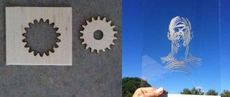
What materials can be processed?
The device is used for processing and creating patterns on many types of surfaces:
- Mirror.
- Glass.
- Stone.
- Acrylic.
- Leather.
- Paper.
- Cardboard.
- Tree.
- Veneer.
- Plywood.
And this is not a complete list of possibilities for using CNC cutting. The use of non-contact technologies will make it possible to process even materials of small thickness. Recently, automation of such work was considered impossible in principle. As well as simple creation of drawings for a CNC laser.
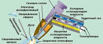
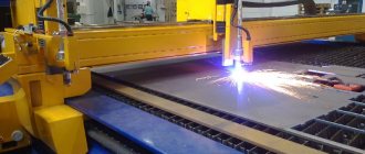
Operating principle of the device
Currently, any laser equipment has an acceptable price level. That’s why it is gaining popularity and is used not only in large but also in small businesses. The drawings with templates presented in this section will also be indispensable assistants. At the same time, high-quality work and high productivity are characteristic of even the most budget models.
To correctly use drawings using cutting, you need to understand what the machine consists of:
- One-piece frame.
- A table located in a horizontal plane.
- Mobile portal. It is equipped with a special head that emits a laser beam.
A stepper motor allows you to set the equipment in motion. A numerical program circuit organizes the adjustment of all parameters. A Numerical Control device installs the laser at certain positions along with other devices that perform work operations.
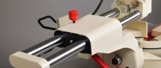
The assembly optics unit also has several components.
- Laser tubes.
- Emitter in the form of a head.
- Reflective devices with the shape of mirrors.
- Focusing mechanism.
- Focus lens.
Making a retro game from the 80s or how to prepare layouts for laser cutting
Habr, hello! It so happened that I have long been asked to make an old board game from the USSR - “Battle”. Now the time has come to fulfill the promise, at the same time I decided to show how to create layouts for laser cutting and what happens in the end. There is no great difficulty in this, but there are some nuances.
Many Habr articles on the topic of DIY contain complaints: about the lack of skills in working with a jigsaw, the low rigidity of cardboard, and the difficulty of creating a case. Everyone chooses the way to implement their ideas, but it is important for me to show how easy it is to make a layout in Inkscape, send it to work and receive ready-made parts.
The game “Battle” itself was released in the USSR in the 80s and was clearly based on the Western game “Stratego”. We restored the game using photos from the Internet.
Equipment with capabilities
This equipment has a laser base as its main working tool. It is distinguished by a high power rating. This makes it possible to process materials with different types of parameters. Thanks to such technologies, it is possible to obtain parts with different characteristics and dimensions.
The capabilities of laser installations are worth considering in more detail in order to correctly use patterns with templates.
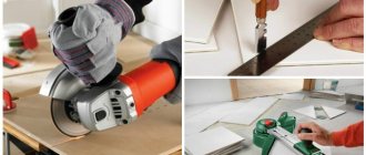
- Cutting.
This is an affordable technology option, although not the most effective. A laser cutter uses less energy than a plasma cutter to do the same job. Even when using heat treatment. The advantage of this type of cutting is the accuracy of the edges and the ability to preserve optical properties.
How to create a layout of an interior word for laser cutting
In this article I will describe the basic requirements for files and some techniques for creating layouts for laser cutting and engraving. I will consider examples based on the CorelDRAW Graphics Suite x6 program. Generally speaking, files can be prepared in any vector editor, but in any case, you should consider a few basic rules that will help you save time and money.
1. The file should be saved in *.cdr format (not higher than version x6). Files created in other programs (for example, AutoCAD or Adobe Illustrator) or with other extensions (for example, *.dxf, *.plt or *.ai) sometimes display incorrectly and may require modification.
2. The layout should not contain raster images, auxiliary lines, colorless or white lines, or fills.
3. The layout must be made on a scale of 1:1. It is recommended to duplicate the overall dimensions of the product in the explanation to the file.
4. All cutting elements must be placed on one page. We also do not recommend doing the cutting yourself.
5. It is not permissible to use line thickness to construct an image. All lines in the file must have a Hairline thickness.
6. All circuits, unless otherwise provided initially, must be closed. This is especially true for contours for engraving elements.
7. Double lines and debris should be avoided on the layout. For example, small elements that were not removed, remaining after the construction of the drawing, very sharp corners, kinks, steps, poor mating of arcs. Since the price of the product is calculated based on the cutting length, the presence of such errors can seriously increase the final cost of the work.
8. Self-intersection of lines and the use of common cutting lines for different elements are unacceptable. In such cases, the probability of marriage is high. Excessive number of knots should also be avoided.
9. It is not allowed to overlap elements. Such elements need to be “merged” into one.
10. When combining cutting and engraving or contour cutting (not cutting through) in one product, different contours should be marked with different colors.
11. All characters and text must be converted to curved lines.
12. It is also worth considering the strength of the structure in advance and not making the load-bearing elements too thin.
As an example, let's look at preparing a vector file to create an interior word on a stand “happiness” 50 cm long from 6 mm plywood with combined letters. I will consider this example in CorelDRAW Graphics Suite x6.
1. First, let’s create a new file in CorelDRAW by clicking on the selected elements or from the “File” menu - “New” (Ctrl+N).
2. Let's use the "Text" tool (F8) from the toolbar on the left side of the program. Let's write the word "happiness" in upper case. Then select the font from the drop-down list on the properties panel. If you don’t like any of the presented fonts, then there are a lot of font selection sites on the Internet. In our example, I'm using the font "Cooper".
3. Select our text and convert it to curves. Be careful, as after this you will no longer be able to change the font or make edits to the text.
4. Remove the fill and make the outlines black. To do this, select all the elements and click with the left mouse button (LMB) on the crossed out white square, and with the right mouse button (RMB) on the black square in the color panel. Then select the “super thin outline” line thickness in the properties panel. And disconnect all our lines (drop-down panel “Arrange” - “Disconnect Curve”).
Now you can select each of the lines separately. We will need this to merge all the letters together and our word will be cut out without breaks.
5. Let's make sure that the letters touch, but do not overlap each other too much with their edges. To do this, we will select each of the letters by pressing and holding LMB and selecting with a frame or clicking LMB on the line itself. To select multiple lines, you need to additionally press and hold Shift. To move elements around the workspace, you can use the keyboard arrows or move elements with the mouse by holding down LMB and Shift (while holding Shift, the movement occurs parallel or perpendicular to the initial position).
As a result, our word will take the following form.
6. To merge letters into one word, you can use several methods.
6.1.a. Select all the elements and click on the “Create Border” tool in the properties panel. In this case, only the resulting border will remain in the selection.
6.1.b. Let’s additionally select the internal elements of the letters “A” and “b” (holding Shift while clicking LMB on the desired lines) and drag all the elements to a free area of the workspace.
Select unnecessary lines and delete them with the DEL key.
6.2.a. Sometimes it is necessary to manually delete all intersection lines. The “Delete Virtual Segment” tool on the toolbar is suitable for such operations. Select it and use a frame (holding LMB) or simply click LMB to delete unnecessary lines from the drawing. To avoid mistakes, it is better to do this at a large zoom.
6.2.b. With the virtual segment removal method, the lines remain open. Let's lock them down. Select all the elements and in the “Arrange” drop-down menu, activate the “Connect Curves” menu. For most cases, 0.2 mm clearance tolerance expansion will be sufficient. Click "Apply".
In what areas is the equipment used?
This is an important point for those who are just about to purchase machines.
- Creation of souvenir products.
In the production of souvenirs, laser machines have shown high efficiency. It has already been said that non-contact processing makes it possible to create patterns on parts with any parameters. Which makes the entire work process easier. Even pens and USB keys are processed using this technology.
- Information, award products.
Laser machines are convenient to use for making signs with any information. Diplomas made of two-layer plastic, award certificates - and in this area laser machines have practically no equal. The main thing is to choose the right drawings.
- Promotional Products.
The equipment is especially relevant when creating interior and exterior elements. After using the machines, surfaces made of acrylic and plexiglass look good - they have a glossy end, and there are no radii left from the cutter. The smaller the element, the easier it will be to cut it when plasma cutters are used.
- Cutting plywood and veneer.
Laser cutting technology has become widely used in interior design. We are talking about the manufacture of overhead elements, decorating furniture, creating radiator and ventilation grilles. Usually we are talking about elements with a small thickness, fragile.
It is almost impossible to produce such parts using milling machines, because it is difficult to avoid the appearance of chips and cracks and other similar defects. Children's toys, construction sets and individual interior elements can also be made using this cutting technology.
This area is also characterized by the active use of laser cutting of veneer. Especially when it comes to the production of marquetry and inlay. In the Hermitage, many objects were created using this technology.
- Packaging work, changing the structure of foam rubber and plastic products.
Few people will be surprised by packaging made using laser machines. The equipment is convenient because it can be easily and quickly programmed at any time. There is no need to be tied to a specific circulation or set up complex lines for supplying materials. The surface is free of creases during non-contact processing. The surface of the pattern looks beautiful.
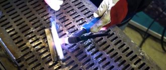
Assembly
We connect the two parts of the playing field and check that everything is going well.
We squeeze out the details of the chips from the chipboard.
We connect the upper and lower parts of the chips.
By the way, here are some close-up photos of what the chip part looks like, cut out by a chipboard.
Front
Behind
To the light
A small protrusion from the jumper is visible on top of the finished chip
Assembling the top and bottom of the game box. The lid had to be glued, but the bottom of the box was assembled without glue.
We put all the components of the game in a box.
We add a printout of the game rules.
Game ready
We tested the product in the game, even unpainted, it’s quite playable!
Known Issues
1. The game requires painting, but my strength and skills are not enough for it yet.
Therefore, the game in this article is presented as “colorless”. 2. The playing field structurally consists simply of a sheet of plywood and all defects in the sheet material are not compensated for in any way. Plywood is a “living” material and its sheets may differ from the plane.
As a result, some edges of the field are noticeably curved upward.
I think that for the field it was possible to choose thicker plywood, in which these defects would appear less.
Defects in the material can also be corrected structurally, for example, by adding a border of side parts to the field (like a box), the mutual connection of the parts straightens the curvatures. 3. I miscalculated a little with the height of the box - I had to make it a little higher, otherwise I have to turn all the chips on their sides, otherwise the box would not close completely.
Additional work tips
The following factors must be taken into account during operation.
- Laser engraving can be used without creating printing forms, cliches and matrices. Accordingly, there is no need to purchase additional equipment or involve more people in processing.
Most operations can be easily performed at home. Just like the preparation of the drawings itself. Cutting them won't be difficult.
This saves time spent on pre-press processing. The production process is accelerated, the productivity of any installation becomes better.
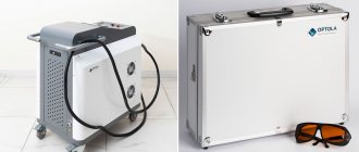
- Laser technologies are known for not requiring the use of large quantities of materials.
Without the laser itself, engraving cannot be performed. The installation is powered by regular electricity. One laser should be enough for approximately 20 thousand hours of continuous operation. Intensive use of one device can last up to 7 years. Even if cutting is carried out constantly.
- One operator is quite capable of servicing the installation. The main requirement is the ability to work with graphics programs.
- Products can be manufactured in both small and single batches. For the design of drawings and their direct production, working files are created in a special program.
- The result of any work is obtaining durable images that are resistant to any external factors. The drawing can be saved for future use.
Preparation of layouts
To perform laser cutting, you need to prepare vector files; we will use the free Inkscape editor. Before you start, it is important to configure the editor correctly.
By default, Inkscape calculates the size of objects along with the thickness of the stroke line; this calculation method is not suitable for laser cutting.
Sequentially select the desired settings panel: Preferences (Shift+Ctrl+P) -> Tools and switch the “Bounding box to use” parameter to “Geometriс bounding box”
(instead of the default “Visual bounding box”) (In the Russian version of the interface, the settings are named as follows: Options (Shift+Ctrl+P) - Tools -> Used area (BB) - “Geometric area").
It is also advisable to set millimeters as the main units in the document settings: File -> Document Properties... -> Display units: mm.
The original game field was made of cardboard and folded in half, the image on the field was formed only by two colors - blue and green. These colors were used both as the colors of the enemy troops and the colors of the map (lakes and forests).
From an old photograph of the game we found, we obtain vectors for groups of images: faces of military officials, forests and lakes. For each group, we prepare a separate raster file, which will not contain any other images except the selected group. We will get three raster images: with one row of faces, with two central lakes and with contours of greenery (forests). We add the resulting images to Inkscape and vectorize them separately; in the vectorization parameters, we set vectorization to consist of two colors.
The game grid, numbers and names of ranks do not need to be vectorized - it’s easier to create new ones.
Create a vector document of the game field. First, we form the grid of the future game from vector lines, then add vectorized images to their corresponding places. We manually add texts with numbers of military ranks and names of ranks. We convert all texts to curves.
We copy a number of ranks on one side of the field to the opposite side.
As a result, we get a vector image of the playing field ready for printing. But we plan not to print the field, but to cut and engrave it. It is required to indicate on the sketch for each line how it will be processed. Processing methods are specified by specifying a unique (within the sketch) line color.
Our playing field has only one contour to cut - its outer edge - let's give it a black color. For the grid lines, contours of greenery and lakes, we will set the color purple - we will engrave them with a line. We will set the portraits, names and numbers of military ranks in a third color - red, this is also engraving, but for now we leave the option of making a solid engraving for them or just a line, which is why we select a separate processing color.
The playing field turned out to be large, 260x326 mm, to make the game more convenient to store and require a smaller box - we will divide the field into two collapsible parts, connected to each other like puzzles.
In the original game, the pieces are bent from cardboard and placed in plastic stands. The design of the chips will be different from plywood; we will make a rectangular base-stand and vertically place the part with the unit number on it. We connect the upper and lower parts using the standard tongue-and-groove method. The height of the tenon and the width of the groove must be equal to the thickness of the material, in our case it is 2.9 mm. The lengths of the groove and tenon are the same, but their dimensions after cutting will differ by the thickness of the cut line, i.e. the tenon will fit into the groove with a gap. So that the parts can be connected without glue, we will add special thickenings in the form of arcs (0.25 mm protruding from each side) to the tenon, which will ensure the connection of the parts with light force.
We need to make 42 chips for each player; making each chip as a separate piece is low-tech and expensive. It is difficult to work with small parts that fall to the bottom of the machine when cutting; they must be collected, sorted, counted and packaged. The smaller the part, the more difficult it is to work with. For such cases, cutting parts with a “chipboard” is well suited, when there is one large parent workpiece, and in it there are many child small parts, whose contours are not completely cut and they are held in the parent part by jumpers. Child parts can be extruded from the parent part with light force.
In the sketch, cutting with a chipboard can be realized as breaks in the lines of conventional cutting. The width of the gap depends on the thickness of the laser cut and the material being processed. For 2.9 plywood I use 0.17mm gaps for pieces that have either side smaller than 50mm and 0.22mm for larger pieces.
But the formation of cutting with a “chipboard” is automated; it is enough to indicate your type and color for such lines.
We create a rectangular parent block and place all 42 tiles on it - two parts for each tile (top and bottom). We place rank numbers, mines and flag figures on the chips. We leave two spare chips without images.
Set processing colors:
- for the contours of chips - blue-green color (cyan) - cutting with a “chipboard”,
- for the contour of the base part and slots - black - normal cutting,
- for images on chips - red - line engraving.
This blank will need to be made in two copies (for each player).
We make a box with a lid for storing the game using the same tongue-and-groove technology, but I have a ready-made generator of boxes according to size, and that’s what I’ll use. We set the internal dimensions of the box: 270x178x32 mm and get ready-made box layouts.
On the lid of the box we will apply an image based on the original box. Unfortunately, the pattern from the box is not suitable for automatic vectorization, so I had to spend time and apply the necessary image lines manually.
It is convenient to make the sides of the box and lid into a chipboard, so that instead of 8 parts you get two. As a result, we received 4 blanks for the box:
Laser engraving: more about the technology
When using this technology, it is assumed that the material is removed from the surface of the workpieces by sublimation. The result is achieved by exposing the surface of the material to a focused laser beam. Maximum power is maintained when cutting. The main thing is to correctly manage the installation parameters to achieve the desired result. Laser engraving works on many of the same principles as a printer. The equipment is as convenient as possible due to the fact that almost no step is carried out manually. This is only required when preparing drawings. And in its finished form, the image will last as long as possible, without any damage.