Electrical installation and commissioning work is always associated with measuring the characteristics of the electrical network, checking the presence of voltage and the operability of the circuits of a device or line. There are a huge number of different measuring instruments and testers for these purposes, but the most versatile and useful device for home craftsmen and professionals is a multimeter. In this article we will look at how to use it.
Voltage and multimeter
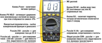
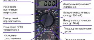
Let's see how to measure voltage with a multimeter. First of all, you need to check the location of the device toggle switch. To prepare the device for measuring voltage, you need to turn it from the off position (indicated as “OFF”) to the V~ mark (the English letter “V” and a wavy line indicating alternating voltage). On some multimeters this mode is abbreviated “ACV”. AC Voltage Test Steps:
- Install the red probe into the socket marked “V/Ω” or “VΩmA” (this is the positive potential), the black one into the “COM” socket.
On a note ! Since alternating voltage has no polarity, installing the probes into the precisely indicated connectors does not play any role. But if the black probe hits a phase, then the number on the screen may be negative.
- Check the switch (it should be at the V~ mark).
- Setting the test level (if you plan to measure alternating voltage in an electrical network with a nominal value of 220 Volts, you should set the test level to a slightly higher value, for example, 236 V, or perhaps to the maximum).
- Inserting the probes into the socket, for the voltage in which it is necessary to check.
Numbers indicating the desired alternating voltage will appear on the screen of the electronic multimeter.
Dial multimeter in the off state Source img1.bgxcdn.com
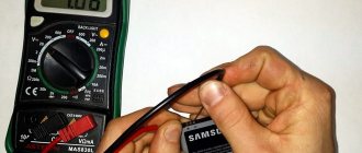
Next, we'll look at how to use a voltage tester to check battery voltage. To measure DC voltage with a dial or electronic multimeter, insert a red and dark probe into the “V Ω mA” and “COM” sockets, respectively, then turn the switch to “V-”.
After setting the verification level (you will need to set it, as in the previous example, to a slightly larger digital value than the intended measurement object has). The two free ends of the probes must be connected to the object being tested (for example, to the two ends of a battery), observing the polarity (“+” and “-”).
On a note ! If you make the wrong polarity, the multimeter will show a negative value, but the value itself will be the correct number; you need to swap the probes on the battery so that the polarity is correct.
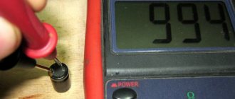
If a value with one or two zeros in front, but without a comma, appears on the device screen, it means that the test level was set too high. It is necessary to achieve a normal number by gradually reducing it and taking measurements. For example, for a battery the value “008” may first appear, and after the indicated manipulations - “8.9”. This means that the battery voltage is approximately 9 Volts.
The multimeter shows the battery voltage Source masteram.com.ua
When “1” appears on the screen, the pre-selected measurement threshold may be too high, then it needs to be brought to a suitable value by gradually decreasing it.
Classification
Currently, all multimeters (testers) are divided into two types: a dial multimeter, also known as analog, and digital. Electricians have been using dial multimeters for a long time, but working with this type of multimeter is difficult.
- It is not easy to understand several scales.
- It is necessary to hold the device itself in a certain position so that the needle on the scale does not “walk”.
Therefore, more and more craftsmen give their preference to digital rather than analog multimeters.
Therefore, it will be he who will be considered. It should be noted that the modern market offers a wide range of multimeters, which includes almost any offer. But it should be noted that there is a certain proportionality in which the relationship between price and functionality of the device is direct. That is, the more expensive the device, the more functions it has. Manufacturers offer expensive models similar to oscilloscopes. At the household level and for beginner radio amateurs and electricians, simpler multimeters for dummies are suitable. They all have the same design, and their appearance is almost the same.
The package of such testers includes the device itself and two probes: red and black. Power is supplied from a 9-volt Krona battery (energy consumption is minimal). This is the whole kit.
Before moving on to the main issue of the article - how to use a multimeter of any type: all the subtleties - you need to familiarize yourself with its functional devices and learn how to operate them. In principle, the rules of use are quite simple.
Checking the current strength
Let's see how to use the tester to find out the current strength:
- Insert the red connector into the socket marked “mA” (“VΩmA”), the black one into “COM” (to check the current strength, the value of which does not exceed 10 Amps). To check the current, which ranges from 200 milliamps to 10 amperes, you should put a red electrical probe into the “10A” connector.
Different positions of drills to determine small and large currents Source www.sciencebuddies.org
- Place the switch on the “A~” mark to check the alternating current value or on the “A-” mark to check the direct current strength.
- Set the measurement range so that it is greater than the expected current strength, but not by much.
- Connect the load (for example, an incandescent light bulb with a socket) into the assembled electrical circuit from the outlet to the multimeter.
Important ! You cannot touch the circuit elements that are not insulated with your hands and the ends of the probe.
- Attach a piece of wire to the lamp base, and the other end to the probe.
- Take another wire and attach it according to the “lamp base - electrical outlet” diagram.
- The red probe (its free end) must be set to the “+” of the object being measured, and the black probe must touch the next element of the circuit (the wire coming from the “load”, that is, from the light bulb).
Remember ! For correct, and most importantly, safe measurement of current, it is necessary to connect the multimeter to the electrical circuit in series, since in ammeter mode the resistance of the multimeter circuit is minimal and if connected in parallel there will be a short circuit.
Connection diagram for a multimeter with a “load” Source electrikmaster.ru
See also: Catalog of companies that specialize in electrical and heating systems
A multimeter can also be used to determine the amount of AC current consumed (for example, for a household appliance). After installing the switch on the direct current symbol (“A-”), you should arrange the probes as follows: for high current - the extreme left position (o), for low current - the middle position (o).
Having set the measurement range approximately corresponding to the current, but slightly larger, you can proceed to the next stage, not forgetting that the device can only be turned on in an open circuit (as in the previous example).
GOST
Test methods for digital multimeters, as well as general technical requirements, are fully described in GOST 14014-91.
Each device must have a passport, which certifies its technical characteristics and parameters guaranteed by the manufacturer.
In addition, measuring instruments (MI) registered in the State Register exactly comply with all standards required for them on the territory of the Russian Federation and are officially approved for use.
To confirm registration in the register, such multimeters receive an appropriate certificate.
Metric system and uncertainty
Digital multimeters display measurement results on the screen in the metric system.
At the same time, for devices there is such a thing as digit capacity, which indicates how many full and limited digits can be displayed on the screen.
This indicator is closely related to the error of the meter, and for most of the simplest models it is 2.5 (an error of about 10%).
For a bit depth of 3.5, the error is usually 1.0%, for 4.5 – 0.1%.
The last bit value indicates that the display displays 4 full digits (digits 0 - 9) and 1 in a limited range (0 - 1), and these are readings in the range of 0.0000 - 1.9999.
There are models with bit depth higher than 5.
In addition to the simple notation, where the number of full digits is indicated before the decimal point, and a limited range within 0 - 1 after the decimal point, there is another one of the form x^y/z, for example, 4^5/6. Here 4 (x) indicates the number of full digits, 5 (y) is the maximum value of an incomplete digit, 6 (z) is the number of values that an incomplete digit can take (0, 1, 2, 3, 4, 5 are 6 digits) .
There are precision multimeters whose display has 8.5 digits, but their error is highly dependent both on the parameter being measured and on the specific subrange. On average, the error for 5 or more digits is 0.01% or lower.
Verification and calibration
Multimeters entered in the State Register undergo mandatory initial and periodic verification with an interval of 1 year, which includes metrological control of each measuring channel.
The initial calibration of multimeters is carried out at the factory, and the manufacturer indicates the maximum permissible range of deviations in the passport.
However, two identical instruments may be calibrated with different accuracy.
For multimeters, there is a calibration technique that requires setting the initial reference voltage parameter - VREF.
The most accurate measurement results are obtained provided that the reference voltage is equal to the ideal voltage.
As a source of reference voltage at home, you can take the REF5050 5 V microcircuit, the error of which is only 0.05%.
That is, calibration of the readings of each value is carried out by connecting the device to a source of the same value with its known parameters and a small source error.
Multimeter and resistance
To find out the resistance of any radio component, use a conventional multimeter. Measurement algorithm:
- Insert the probes (black – into the “COM” socket, red – into the socket marked “V/Ω” or “VΩmA”).
- The switch will need to be moved to the “Ω” position.
- At the third stage, it is advisable to check the serviceability of the device by connecting the two remaining free ends of the probes. The multimeter is working if it shows a zero value.
- Set the measurement limit to the expected approximate average value (for example, 2 M).
- Connect electrical probes to the coil (to the measurement object).
What will be the coil resistance? Source cdn.sparkfun.com
- Look at the display (screen) of the device.
If several zeros appear, the coil has resistance, but the measurement limit will need to be lowered slightly to see the actual digital resistance value. The same must be done when a number appears in front of the numerical value on the electronic multimeter, but with a zero (zeros) at the beginning. If a unit occurs, it is worthwhile, on the contrary, to reduce the set denomination.
Testing with a multimeter
The multimeter has several more functions, one of which is the so-called continuity test. It is used to search for a break in the neutral wire in an electrical circuit.
Algori:
- connect the red probe to “V/Ω”, the black one to “COM”;
Testing wires with a multimeter to check their integrity Source avatars.mds.yandex.net
Checking radio components
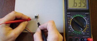
If a radio amateur has a digital multimeter, he must know how to use this device to test the functionality and measure the characteristics of transistors, diodes and capacitors. Everything is very simple here:
A black probe should be installed in the COM socket, and a red one in the VΩmA socket.
The black probe (its second end) must be connected to the cathode of the diode (to the “minus”) of the part being tested, and the red one, respectively, to the cathode of the anode (to the “plus”).
The resistance of the part will be displayed on the screen.
If in any position (as in the described algorithm or with the reverse arrangement of the probes connected to the anode and diode) one is displayed, this means that the part has burned out. If the reading is less than one, the diode is broken.
Video description
You can see more details about how this test is carried out in the video:
To check the transistor, you need to switch the multimeter to the “hfe” mode and combine the three outputs of the part with the connectors on the device. They are called "B", "E" and "C" and correspond to the "base", "emitter" and "collector" on the transistor. If the connection is correct, the gain value of the radio component being tested will appear on the multimeter screen.
So, how to use a multimeter tester to check the capacitor for its capacity: this part must be inserted into the corresponding connectors on the device (the “CX” sector). By twisting the toggle switch, you can adjust the measuring limits to the required numerical value.
Electrician's tool
Even the most experienced electrician can do little without the appropriate set of tools, this is understandable - you can’t even unscrew an outlet with your bare hands. Let's consider the minimum set of necessary tools. This is a set of various screwdrivers - figured and flat, pliers, side cutters and a knife. It's a good idea to add platypuses and a wire stripper to this list. I’ll make a reservation right away - you can’t skimp on a tool; it must be reliable, convenient and well insulated. Although there is no point in leading to fanaticism, there are often “masters” who compensate for the lack of knowledge and experience with an abundance of unreasonably expensive tools. It is best to take an old, time-tested instrument in the middle price category. Such as shown in Figures 22 – 27. In addition to the mechanical (described above) tool. You must also have a tester (multimeter, Fig. 28) and a voltage indicator (Fig. 29).
Electrician's tool
To begin with, the listed tool is quite enough, but over time its number will increase. Also in the future you will need power tools - a hammer drill, an angle grinder, a screwdriver. All this will be acquired over time and the number of tools will constantly grow. You can also add consumables to the tools. These include electrical tape, heat shrink, caps. connecting clamps and terminal blocks. A handful of all this stuff should always be on hand.
Prices for sets of electrical installation tools
Set of electrical installation tools
Video description
Learn how to quickly check a car battery with a multimeter in this video:
Checking a car battery using a multimeter Source mobilehomepartsstore.com
Further measurements will be made in the same way. To measure the current strength in the wiring of your car or for a separate electrical appliance, you should first find out what kind of current you need to check (for example, the “DCA” marking indicates constant). To measure resistance, set the toggle switch to any position, and do not forget to turn off the power to the network.
Briefly about the main thing
Any car enthusiast, radio enthusiast, or anyone who encounters electric current or the operation of household appliances should know how to use a multimeter correctly.
By following a few simple steps, you can find out the voltage, current, and resistance of an electrical circuit using any type of multimeter.
Car batteries, radio components and electrical devices can also be examined using a multimeter tester.
Ratings 0
Safety precautions when working with the tester
- Before starting work, read the “safety” section in the instructions.
- Make sure that the housing is intact and that the connecting screws are fully tightened. In many devices, replacing the battery requires disassembling the housing. Many users then simply snap the halves together, forgetting to secure the screws.
- Check the reliability of the connection of the measuring cables in the connectors. To do this, it is enough to pull the wire with a little effort while holding the insulator in your hands.
- When working with voltages greater than 60 volts, do not hold both test leads with different hands. By fulfilling this simple requirement, you will protect yourself from electric shock along the so-called “line of death”: hand-heart-hand.