Current strength is a quantity that characterizes electricity. In addition to it, power, voltage, and frequency are distinguished. It is measured in amperes, and it is designated, both in the Russian and in the international system of units (SI), by the symbol “A”. Knowing this value makes it clear how many charged particles rush through the cross-section of the wire at a certain instant. That is, what is the intensity of the flow of electricity in the conductor. This can be compared to the pressure of water in hoses. Only instead of water, electrons flow in the conductors. The greater the “pressure” of electrons, the greater the current value.
To better understand the meaning of current, let's again compare electricity and water in hoses. If the water hoses are of small diameter and the pressure is strong, the hoses will not hold up and will burst. The same thing happens with wires. If the current in the wires to which the electrical appliance is connected is greater than they can withstand, the wires will simply burn out. This principle is the basis for the operation of fuses, which, by burning themselves, protect electrical wires from burning out. Therefore, in order to understand whether it is worth connecting the device to the electrical network, you need to know the critical current values that the wiring can withstand.
You can measure the current with a multimeter. This device can also make other measurements characterizing electric current, but now we will talk specifically about determining its strength.
Basic principles of current measurement
The main feature of working with a multitester in ammeter mode is that it must be included in the open circuit.
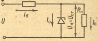
This connection is called serial. In fact, the device becomes part of this circuit, that is, all the current must pass through it. And as you know, the current strength in any section of an unbranched electrical circuit is constant. Simply put, how much “goes in” is how much must “go out.” That is, the location of the serial connection of the ammeter does not matter much. To make it clearer, below is a diagram that shows the difference in connecting a multimeter in different operating modes.
Differences in the principles of connecting a multitester in different measurement modes
- So, when measuring current, the multimeter is connected to the open circuit, becoming one of its links. That is, there will be a problem of how to practically organize this circuit break. They solve it in different ways - this will be shown below.
- When measuring voltage (in voltmeter mode), the circuit, on the contrary, is not broken, and the device is connected in parallel to the load (the section of the circuit where the voltage is required to be determined). When measuring the voltage of a power source, the probes are connected directly to the terminals (socket contacts), that is, the multimeter itself becomes a load.
- Finally, if resistance is measured, then the external power source does not appear at all. The contacts of the device are connected directly to a particular load (the section of the circuit being called). The required current for measurements comes from the multitester’s autonomous power supply.
Let's return to the topic of the article - current measurements.
It is very important to initially correctly set the measurement range on the multimeter, in addition to direct or alternating current. I must say that beginners often have problems with this.
Current strength is an extremely deceptive quantity. And it’s as easy as shelling pears to “burn” your device, or even cause big trouble, by incorrectly setting the upper measurement limit.
You should start measuring current strength, especially if you have no idea about its possible value in the circuit, from the maximum range of the multitester. If necessary, you can rearrange the wire and successively lower the upper limit to reach the optimal one.
Therefore, a strong recommendation is that if you do not know what current strength is expected in the circuit, always start measurements with the maximum values. That is, for example, on the same DT 830, the red probe should be installed in a 10 ampere socket (shown in the illustration with a red arrow). And the operating mode switch knob should also show 10 amperes (blue arrow). If measurements show that the limit is too high (readings are less than 0.2 A), then in order to obtain more accurate values, you can first move the red wire to the middle socket, and then the switch knob to the 200 mA position. It happens that this is too much, and you have to use a switch to reduce it another level, etc. It’s not entirely convenient, we don’t argue, but it’s safe for both the user and the device.
By the way, about safety
Safety precautions should never be neglected. And especially if we are talking about dangerous voltages (and mains voltage 220 V is extremely dangerous) and high currents
We are calmly talking about amperes here, but meanwhile, a current no higher than 0.001 ampere is considered safe for humans. And a current of just 0.01 ampere passing through the human body most often leads to irreversible consequences.
It is recommended to carry out current measurements, especially if work is carried out in the highest range, as quickly as possible. Otherwise, the multitester may simply burn out.
By the way, warning signs near the test lead connection socket can also inform you about this.
An example of a warning notice at the wire connection socket for measurements on the maximum permissible current range
Note. The word “unfused” in this case means that the device in this mode is not protected by a fuse
That is, if it overheats, it will simply fail completely. The permissible measurement time is also indicated - no more than 10 seconds, and even then no more than once every 15 minutes (“each 15 m”). That is, after each such measurement you will also have to take a considerable pause.
To be fair, not all multimeters are so “picky”. But if there is such a warning, you should not ignore it. And in any case, measure the current strength as quickly as possible.
NET.Gadget
Articles
How to check amps with a multimeter? annotation
A multimeter is a device that is used to measure voltage, current, resistance, and test wires. In other words, this device is quite necessary. With all this, as practice shows, it is quite popular not only in the industry, but also in everyday life.
Alas, once a competent installation is carried out and how to proceed with the necessary measurements, it should be taken into account that a multimeter. Not a completely safe device. If used incorrectly, of course, it will not only simply disable it, but also cause severe harm to one’s own health. This is especially true in cases where your company needs to take measurements at high voltage or high current. It won't be difficult to just immediately burn the multimeter and get severe electrical injury.
That’s why, before you can properly install and start using a multimeter, you need to practice on power sources with low current ratings, for example, batteries. It is also not recommended to misuse the instructions for the device.
Types of multimeters
First you need to know that multimeters are digital and analog (pointer, even among electricians they are known as “tseshka”). The latter have been known to electricians for a long time, but it is quite difficult to use them without special knowledge and practice.
- you need to be able to understand the scales of the device, of which there are several on the dial multimeter;
- The device should be kept in a position where the needle on it will not “walk” along the scale.
That's why, if possible, it is better to use a digital multimeter. We will also consider examples with the implementation of a specifically digital device, because it is quite difficult to learn how to work with analog multimeters without the help of others.
There are quite a few varieties of digital multimeters, but the principle of their operation is similar to each other - the difference lies solely in the number of functions of the device. Accordingly, the cost also depends on the functionality of the multimeter, so before you get it, decide why you need it.
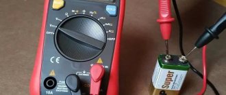
The multimeter consists of:
- the device itself;
- 2 probes (dark and reddish);
- power source (9 V Krona battery).
So, what are the features of using this measuring device and how?
Instructions
In order to measure the current in a circuit, you need to connect the device to it one by one. With all this, on the multimeter itself you need to plug a reddish-colored probe into the socket on the device labeled mA, and a dark one into com. A serial connection means that the circuit must be broken and each probe is connected to a different wire, i.e. the device must be connected between 2 power sources. But because you are measuring current strength, and this is simply impossible to do in power supplies, you need to include a certain device in the circuit, for example an ordinary light bulb, placing it in the circuit immediately after the power source.
How can you simply check your charger
multimeter. Watch my other videos from the useful category.
How to measure voltage
Having figured out what kind of current movement occurs, where, you can begin the direct measurement process:
- voltage in the socket;
- accumulators, batteries.
Let's look at the sequence of actions for each of them.
Measuring voltage in a socket
Having taken a multimeter and connected the wires to it according to the technology given above, all that remains is to take a few simple steps:
- set its value to the “Alternating voltage” item. An icon of the letter "V" with a small sine wave above it. Or in some cases - “ACV”;
- find out the approximate current strength of your outlet (in most cases, if you check the voltage, it will be 220 Volts in a standard network);
- set an approximate range based on the previous value. It is advisable not to make large runs, otherwise there is a possibility of getting an incorrect result. The reference point is 700-750V.
- connect the second ends of the terminals to the socket, feel the wire inside with them. With alternating current there is no difference in the location of the poles (plus/minus), so you don’t have to think about it and place them at any hole.
This way you can measure the voltage in the socket with a multimeter and get the correct answer displayed on the device’s display.
Instructions for measuring DC voltage in a battery or battery
To check the voltage with a multimeter, for direct current batteries, the circuit will be a little similar to alternating current:
- select the device that needs to be diagnosed for voltage;
- on the device, select the icon responsible for direct current;
- All batteries have their own limits, their data is located on the case. Study the information carefully;
- set the required limits on the multimeter;
- connect the plugs to the measuring device (as indicated earlier);
- the second ends of the wires are connected to the battery terminals: the black probe to the minus, the red probe to the plus of the source that currently needs to be measured;
- keep the wire and battery in the installed position until the numbers on the screen stop increasing;
- after that, the last highest value will appear on the multimeter monitor, and it will be correct, indicating the corresponding energy reserve.
What to consider when measuring
An important condition when determining the current strength is the inclusion of a limiting resistance in the circuit - a resistor or an ordinary light bulb. This element will protect the device from damage (combustion) under the influence of electron flow.
If the current strength is not displayed on the indicator, this indicates an incorrectly selected limit that needs to be reduced by one position. If there is no result again, do one more, continuing until some value is displayed on the screen or scale.
The measurement must be taken quickly - the probe should not be in contact with the cable for more than one or two seconds. This is especially true for low power batteries. If, while measuring the battery current, you hold the probe on the wire for a long time, the result will be their discharge - partial or complete.
Measuring current with a multimeter
If you need to measure current, you must select and switch to the position corresponding to direct or alternating current in advance. Much will depend on the type of circuit being tested and its power source.
After this, the required interval for measurements is set on the device. The upper limit of the interval should be set significantly higher than the expected current strength. These measures will help protect the fuse from blowing, and the multimeter from failure. If a multimeter connected to the circuit does not show anything, then in this case it is necessary to reduce the maximum interval limit.
To take measurements, the multimeter must be connected to an electrical circuit. The most important condition is the absence of high voltage alternating current in it. Even before touching the wires, the circuit being measured must be disconnected.
Then the wire needs to be cut. Its ends are cleaned and connected to the probes. Wires and probes should not touch each other. Once the circuit is turned on, measurements can be taken. After the measurements are taken, the current is turned off again, and the cut wires are connected to each other. This operation is quite simple, so the problem of how to measure current with a multimeter is solved very simply.
Safety precautions
When working with electricity, do not forget about safety precautions and precautions. The following simple rules will help you protect yourself from possible exposure to electricity.
- Do not take measurements at high humidity or on a wet working surface;
- Also, before testing, turn off the power supply;
- Wear rubber gloves;
- It is imperative to check the insulation of the wires along the entire length, since as they are used
- the surface is often worn out and exposed;
- After completing all work, wrap the exposed wires to check.
Checking the battery charge
To perform such actions with a multimeter, you should switch it to the DC voltage measurement mode, setting the range slightly higher than the highest voltage reading on the battery. After this, connect the multimeter probe. Painted black, to the negative pole of the battery, and red, respectively, to the positive pole. The following readings appear on the display of the device:
If the battery is fully charged, then its voltage should not be lower than 12.6 V. Otherwise, the battery charge level does not exceed fifty percent and requires urgent recharging. An indicator not exceeding 11.6 V indicates that the battery is completely discharged. In order for the battery to charge for a long time, it is necessary to identify the causes of current loss, which happens in any car. This is facilitated by the alarm system, radio, dashboard and central locking device. If the total current loss does not exceed 80 mA, then the battery will operate without problems for several years. To operate, the multimeter is set to current measurement mode at 10 or 20 amperes:
Having removed the “negative” terminal, we connect one of the wires of the device. The second we touch the removed wiring. Polarity does not matter in this case:
Correctly measure phase consumption
The house is old - in plain sight you will see a large steel plate that is clearly connected to the body. The signified is neutral. The house is powered by a three-phase voltage of 380 volts. Each apartment is often supplied with one phase. We see three clamps in addition to the ground terminal. Look where the wires go: automatic machines, switches (according to the number of apartments). A typical number of site neighbors of three simplifies the analysis task.
Now we know the method for finding the phase with a multimeter, we can safely (with caution, observing safety measures) poke with probes. Take care to set the correct range so as not to burn the device
Use measurements to confirm or refute your assumptions. There are two phases - load each equally. Examine the junction boxes, located near the ceiling (large round holes in the wall) in most older homes. Having turned off the supply to the apartment, armed with a tester, understand where and what is going. Use a radical method - cut off one plug, look where the power is lost.
The load of the two phases is uneven - correct it. It would be better to do it for automatic machines and traffic jams, which will have a positive effect on reducing the cost of switchboard equipment. To complete this topic, let’s say that the work rules provide for the implementation of such activities by at least two people. One is sure to insure and is ready to cut off the power supply, cut off the current-carrying wire, or kick the person suffering from an electric shock away from the dangerous territory.
Apartment power supply diagram with two phases
What parameters can a multimeter measure?
Using a multimeter, you can accurately determine voltage, capacity, amperage, etc. when checking a battery. Let’s look at it in detail one at a time.
Capacitance measurement
How to properly check battery capacity with a multimeter? To do this, you need to test discharge the battery, but before that it must be fully charged. You should make sure that the charge is complete, and only then can you measure the density of the electrolyte composition and voltage.
Next, a device with a certain power is connected, for example, a light bulb.
When the voltage of a fully charged power source drops to 50%, the incandescent lamp must be turned off. The capacity is calculated using the following formula: the current strength in the circuit under additional load is multiplied by the hourly period during which the control discharge of the battery lasted.
Looking at your passport
The first way is to look at the passport of the electrical appliance. All factory units are supplied with a label on the body, instructions and a passport with a guarantee. These booklets indicate the scope of application, operating conditions, and technical data.
Above is a small fragment of passport data, or rather a table with data on the model range of convector heaters. Column No. 1 indicates the current passing through the device, the second column indicates how much electricity the device consumes when one heating element and two are turned on. Using the heater as an example, you can easily find out the power consumption of the device using the passport. In a similar way, you can determine how much a TV or even an LED lamp consumes.
How to measure the voltage in an outlet
A fairly common situation is when household electrical appliances: electric kettle, refrigerator, washing machine, etc. temporarily stop working normally. Before calling a technician, it is useful to make sure that the voltage in the outlet corresponds to the permissible level. Therefore, let's look at how to use a multimeter when measuring voltage in an outlet. The mains voltage is variable and has a life-threatening value - 220 V (according to the old GOST) or 230 V according to the new GOST. Therefore, first of all, you should adhere to safety rules and under no circumstances should you touch bare, non-insulated conductive parts of an electrical circuit with your bare fingers. Including probes and socket contacts.
These measurements should be taken carefully. The opposite ends of the probes must be installed in the corresponding connectors (the two bottom ones, similarly as in the previous case)
Next, use the switch to select the desired mode. It is marked on the body in the form of the letter V, next to which there is a wavy line ~, called a “tilde”. This sign in electrical engineering symbolizes variable quantities. In the sector we see only two values: 200 V and 750 V. We move the switch to the number 750 V. Next, we touch the socket contacts with the probes. According to safety rules, both probes must be held in one hand.
Looking at your passport
The first way is to look at the passport of the electrical appliance. All factory units are supplied with a label on the body, instructions and a passport with a guarantee. These booklets indicate the scope of application, operating conditions, and technical data.
Above is a small fragment of passport data, or rather a table with data on the model range of convector heaters. Column No. 1 indicates the current passing through the device, the second column indicates how much electricity the device consumes when one heating element and two are turned on. Using the heater as an example, you can easily find out the power consumption of the device using the passport. In a similar way, you can determine how much a TV or even an LED lamp consumes.
How to measure capacitance
The multimeter can also be used as a tester to measure battery capacity. The battery capacity can be measured using a test battery discharge. To check the capacity, you will first need to fully charge the battery. Then you need to make sure that the battery is fully charged by measuring the voltage and density of the electrolyte.
Next, you need to connect a load of known power, for example a 24 W incandescent lamp, and note the exact start time of this experiment. When the battery voltage drops to 50% percent of the previously set reading of a fully charged battery, the light should be turned off.
Capacity measurement, which is expressed in a/h, is carried out by multiplying the current in the circuit with a connected load by the number of hours during which the control discharge of the battery was carried out. If you get a value that is as close as possible to the nominal a/h value, then the battery is in excellent condition.
How to test a capacitor with a multimeter
In order to check the integrity of the capacitor with a multimeter, its capacitance must be 1 µF or higher. This trick only works with analog multimeters, as well as with digital range selecting multimeters, such as these.
As you know, capacitors are polar and non-polar. Read more here. Polar capacitors have a large capacity, so they are easier to check for functionality. How to do this? Let's take a look at the example below.
We have an electrolytic capacitor.
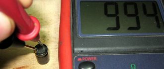
We set the multimeter to the continuity mode and touch the leads of the capacitor with the probes. We carefully watch the numbers on the scoreboard. They should increase as the capacitor charges.
As soon as I touched the leads, the multimeter immediately showed this value
in half a second
and then the value went out of range, and the multimeter showed one.
So what can we say? At the very initial moment of time, a completely discharged capacitor behaves like a conductor. As it is charged with current from the multimeter, its resistance increases until it becomes very high. Once the capacitor is charged, it means it is working. Everything is logical.
Capacitors of smaller capacity and non-polar capacitors can be tested using a tester only for a short circuit between its plates. Therefore, a different iron method is used here. Just measure the capacitance of the capacitor). Here I measured the capacitance of the capacitor, on which 47 uF was written. The multimeter showed 48 uF. Either the error of the capacitor or the multimeter. Since Mastech multimeters are considered to be quite good, we will attribute it to the capacitor error).
Instructions
In order to measure the current in a circuit, it is necessary to connect a device in series to it. In this case, on the multimeter itself, you need to insert the red probe into the socket on the device labeled mA, and the black probe into com. Series connection means that the circuit must be broken and each probe is connected to a different wire, i.e. the device must be connected between two power sources. But since you are measuring current, and this is simply impossible to do in power supplies, you need to include some kind of device in the circuit, for example an ordinary light bulb, placing it in the circuit immediately after the power source.
If you measure alternating current, the device displays the maximum alternating current value (icon A
- note that it looks very similar to the DC icon (A-), so be careful). And only after that you can start taking measurements.
Before checking the amperes with a multimeter, make sure that the current being measured is not too high, since such measurements may be unsafe due to the small cross-section of the probe wires. The latter may not withstand high loads. Experts recommend taking measurements at a current value of more than 10 A using electrical clamps.
Safety precautions
It's easy to check the current strength. It is enough to connect the multimeter in accordance with the operating rules. It is necessary to follow the instructions in order not to violate safety precautions:
- The device is connected in a de-energized state.
- Pre-inspect the insulation on the wires. With a long service life, its integrity is compromised. There is a possibility of receiving an electric shock.
- You only need to measure amperes while wearing rubber gloves.
- Measurements are prohibited in rooms with high humidity. Moisture has high electrical conductivity. The risk of injury increases several times.
- Anyone who has suffered an electric shock, regardless of its power, must be urgently taken to the nearest medical center. It is forbidden to work with electricity alone. In an emergency, your partner can call an ambulance.
- It is strictly forbidden to work with devices that spark or are broken when connected to analog power sources, for example, to a battery, batteries or power supply. All this can lead to electric shock. Not too strong, but capable of harming the human nervous system and heart.
- It is forbidden to use a multimeter after an impact, just as it is forbidden to glue it with tape or insulating tape. It is better to use a new device or entrust it to a specialist for repair and testing for suitability.
After using the multimeter device, the cables that were cut are connected with the circuit de-energized.
A multimeter is a device that is simply impossible to do without in everyday life and other areas. Having even the most minimal knowledge of its operation, you can repair the devices. Knowing the indications, it is easy to determine their unsuitability.
Every electrician knows how to check amperes with a multimeter. This is a device that functions like a voltmeter and other similar devices. Using this technique, it is possible to measure indicators such as direct voltage, alternating voltage, current, resistance power, diode performance, transistor usability, signal transmission frequency.
Parallel connection measurements
With a parallel connection, several branches originate at a certain point in the electrical circuit and all end together at another section. In this case, the total current strength is equal to the sum of the current values on all branches:
I = I1 + I2 + … + In
Multitester measurement technology - how to measure direct and alternating current with a multimeter:
- installing a probe with a black cable into the corresponding color-coded connector on the measuring device;
- installing a probe with a red cable into the tester connector marked “A”;
- switching the toggle switch when measuring alternating current to the “AC” position, and for direct current measurements – to the “DC” position.
Series and parallel connection of batteries
In an electrical circuit with a parallel connection, the device shows the same current strength on each branch, so all the obtained values are summed up.
The measurement limits are set so that they are obviously higher than the expected current strength in the electrical circuit being tested, which will prevent the multimeter from burning out.
Measurement of various devices
Most often, the strength of electric current is tested in sockets, batteries and chargers. Let's consider some aspects when connecting and measuring.
Socket
The first thing to consider when taking measurements at an outlet is the presence of an adapter device in the chain between the outlet and the multimeter. Connecting a multimeter without unloading electronic devices will lead to a simple local emergency
If you do not pay attention to this point, you risk burning the tester. Connect some device to the point under test, creating a circuit of three elements
Ten seconds are enough to get the result. Delaying it for longer is not recommended for the same safety reasons.
Battery
To measure current with a multimeter, set the maximum permissible value on the meter. Next, attach the probe with the black cable to the “minus” and the red cable to the “plus”. To prevent the consequences of such tests from affecting the operation of the source in the future, the probes must be immediately removed after a successful test.
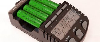
Charger
To measure the current, scroll the selector on the tester to sector A, and set it to the maximum value before taking measurements of the charger. Connect one of the probes to the wire going to the charger at the break point. The tester can easily be burned if you take measurements for more than 15-20 seconds.
Basic Multimeter Operations
Voltage measurement
How to use a digital multimeter to measure voltage? To do this, set the switch on the multimeter to the appropriate position. If this is the voltage in the outlet at home (alternating voltage), then flip the switch to the ACV position. Insert the probes into the COM and VΩmA connectors.
First of all, check that the connectors are connected correctly. If one of them is mistakenly installed in contact 10ADC, a short circuit will occur when measuring voltage.
Start measuring from the maximum value on the device - 750V. The polarity of the probes does not play any role at all. It is not necessary to touch the zero with a black probe, and the phase with a red one. If a much lower value is displayed on the screen, and the number “0” appears in front of it, this means that for a more accurate measurement, you can switch to another mode, with a smaller voltage level scale that your multimeter allows you to measure.
When measuring DC voltage (for example, electrical wiring in a car), switch to DCV mode.
And you also start measuring from the largest scale, gradually lowering the measurement levels. To measure voltage, you need to connect the probes in parallel to the circuit being measured, while using your fingers to hold only the insulated part of the probe so as not to get under voltage yourself. If the display shows a voltage value with a minus sign, this means that you have reversed the polarity.
Some experienced electricians recommend holding both probes in one hand when measuring the voltage in an outlet. If the probes are poorly insulated and breakdown, this will allow you to protect yourself to some extent from electric shock.
The multimeter operates on a battery (a 9-volt crown is used). If the battery starts to run low, the multimeter starts to lie shamelessly. In the outlet, instead of 220V, it may seem like 300 or 100 Volts. Therefore, if the device readings begin to surprise you, first check the power supply. An indirect sign of battery discharge can be chaotic changes in the readings on the display, even when the probes are not connected to the object being measured.
Current measurement
The device can only measure direct current. The switch must be in the – DCA position.
Here, probes, unlike voltage measurements, must be connected in series with the object being measured. That is, you will have to break the circuit and then connect the probes into the resulting gap. This can be done in any convenient place (at the beginning, middle, end of the chain).
In order not to constantly hold the probes with your hands, you can use alligator clips for connection.
Know that if, when measuring current, you mistakenly set the switch to ACV mode (voltage measurement), then most likely nothing bad will happen to the device. But if it’s the other way around, the multimeter will fail.
Resistance measurement
To measure resistance, set the switch to position - Ω.
Choose the desired resistance value or start again with the largest one. If you are measuring resistance on some operating device or wire, it is recommended to turn off the power from it (even from the battery). This way the measurement data will be more accurate. If during measurement the value “1, OL” appears on the display, this means that the device is signaling an overload and the switch needs to be set to a larger measurement range. If “0” is displayed, then on the contrary, reduce the measurement scale.
Calling
Another operating mode of the tester that is often used is dialing.
What is it for? For example, in order to find an open circuit, or vice versa - to make sure that the circuit is not damaged (checking the integrity of the fuse)
The level of resistance is no longer important here, it is important to understand what is wrong with the circuit itself - is it intact or not?
It should be noted that there is no sound signal on the DT830B.
For other brands, as a rule, the signal is heard at a circuit resistance of no more than 80 Ohms. The dialing mode itself occurs when the pointer is positioned - checking the diodes.
It is also useful to check the integrity of the probes themselves by testing them by connecting them to each other. Since with frequent use they may be damaged, especially at the point where the wire enters the probe tube. Before each measurement, be sure to make sure that there is no voltage in the area where you will connect the test leads, otherwise you may burn the device or create a short circuit.
Meet the tester
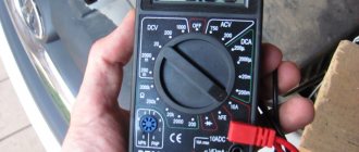
First of all, we will briefly tell you what is on the front panel of the measuring device and what functions you can use when working with the tester, after which we will tell you how to measure resistance, current and voltage in the network. So, on the front side of the digital multimeter there are the following symbols:
- OFF – tester is turned off;
- ACV – alternating voltage;
- DCV – constant voltage;
- DCA – direct current;
- Ω – resistance;
You can clearly see the front appearance of the electronic tester in the photo:
You probably immediately noticed the 3 connectors for connecting probes? So here we need to immediately warn you that it is necessary to correctly connect the tentacles to the tester before taking measurements. The black wire is always connected to the output marked COM
Red according to the situation: in order to check the voltage in the network, current up to 200 mA or resistance, you must use the “VΩmA” output; if you need to measure the current value above 200 mA, be sure to insert the red probe into the socket marked “10 ADC”. If you do not take this requirement into account and use the “VΩmA” connector to measure large currents, the multimeter will quickly fail because The fuse will blow!
There are also old-style devices - analog or, as they are commonly called, dial multimeters. The model with an arrow is practically no longer used, because such a scale has a higher error and, moreover, measuring voltage, resistance and current using a dial indicator is less convenient.
If you are interested in how to use a dial multimeter at home, we immediately recommend watching a visual video lesson:
Learning to work with an analog model
We will talk in more detail later about how to use a more modern digital model of the tester, looking at step-by-step instructions in pictures.
Check internal resistance
To check the battery for serviceability using a multimeter, you need to measure the internal resistance of the battery. You can check the functionality of the power source using a multimeter and a powerful 12 V light bulb. You need to check the battery in the following sequence:
- The 12 V lamp is connected to the battery.
- After a few seconds of the lamp glowing, the voltage at the battery terminals is measured.
- The lamp turns off and the voltage is measured again.
If the measurement difference does not exceed 0.05 V, then the battery is in good condition. In the case where the voltage drop is greater, the internal resistance of the power source will be higher, which indirectly will indicate a significant deterioration in the technical condition of the battery.
In this way, it is possible to fairly accurately check the power source for serviceability.
power unit
Today, a car enthusiast should be armed with all the benefits of technical equipment. These include a garage power supply, which is a powerful, reliable, completely universal device and, most importantly, absolutely safe. It is quite possible to assemble it with your own hands, having at your disposal a transformer and other necessary parts, or purchase it in a store. In the first case, it is allowed not to install a device for measuring voltage; simply the indicator of this value on the block will have to be measured using a multimeter. Working with such a device is quite convenient. It allows you to keep the battery running, start the engine for periodic recharging, and open the garage door for ventilation. With the help of the block, it is possible to check almost all the car’s devices for functionality, and customize car enthusiast designs. The power supply will recharge the battery without any problems, but it should not be used as a starting element - it will definitely burn out.
Multimeter dt9205a instructions for use
This model is very close to the previous one in terms of characteristics.
The same rubber body, the same probes are not of high quality (we recommend immediately replacing them with silicone). Warning: when purchasing silicone probes, it is better to check the correspondence between the diameter of the connector and the socket in the multimeter; some options simply do not fit completely and make it impossible to take measurements.
The main advantages of the device include:
- various measurement modes - from current to capacitors;
- presence of the “phase search” mode. With this option, the red probe is transferred to a device in the studio (for example, an outlet), and the black one is grounded to your own skin. When the phase is in the first digit on the display, the unit of measurement is shown;
- The stand for inclined installation, however, is not very stable.
User disadvantages include insufficient measurement accuracy and fluctuation error: at lower measurement values, the error is larger.
Functional elements of a multimeter
Modern manufacturers produce various models of multimeters. Digital instruments with various additional functions, which are considered more accurate, are widely popular. An error of up to those percentages is considered normal. The lower the deviation indicator, the more reliable the test check.
Even the simplest electrical measuring device is capable of determining the most standard values - current, voltage and resistance. More expensive multimeters are equipped with special sensors for measuring temperature. Also, using such a hand tool, capacitance, intervals between pulses, frequency and inductance are determined.
Among the functional capabilities of the multimeter are:
- Recognition of disturbances in the operation of an electrical circuit. The device is capable of detecting the resistance value, which has fallen below the required scale, using a sound signal - “diagnosis”.
- Checking semiconductor elements. Using a multimeter, you can check diodes, transistors or thyristors, namely their serviceability.
- Many advanced models are equipped with displays that receive a signal and can carry out the necessary calculations.
The most popular additional features are:
- recording of the detected value by the device - push-button or automatic;
- illumination of indicators on the screen;
- power failure counter;
- reboot indicator;
- automatic detection of measurement boundaries.
In professional models, the minimum accuracy error is established. Sometimes digital processing ability is used. The necessary maximum parameters are fixed in the working memory, with the help of which the device calculates the average value.
Also on the front side of the multimeter there is a “continuity” icon and a knob for switching ranges
Almost all multimeters have catchy symbols that display the functional elements of the device:
- “DCA” – direct current measurement;
- “Ω” – resistance icon;
- “ACV” – constant voltage indicator;
- “DCV” is a designation for alternating voltage.
Some electrical measuring devices have two indicators at once - digital and dial. To make it easier to work with the device, two measuring scales are used, which allow you to measure in different values.
The procedure for preparing the device for measurements
The multimeter switch must be moved to sector A (DA for direct current or CA for alternating current), which corresponds to the current measurement, selecting the desired limit. Some modern testers for DC circuits have one position, and for alternating current - another. In order not to make a mistake, you need to be guided by the letters on the front panel.
They are the same in any device, you just need to understand what value each of them represents.
All multimeters are equipped with two cables, at the end of each of which there is a probe and a connector. The second ends of the wires are inserted into the sockets of the device, which correspond to the current measurement, in our case, current strength.