4.6
Average rating: 4.6
Total ratings received: 182.
4.6
Average rating: 4.6
Total ratings received: 182.
The resistivity value characterizes the ability of a substance to limit electric current (provide resistance). Metal conductors have the lowest resistivity values, so they are used for transmitting electricity over long distances, and as connecting wires in electronic devices, and connecting tracks on microcircuit boards. Let's figure out why metals have this property and which of them are best suited for these purposes.
Why resistance occurs
Electrons, colliding with charged atoms (ions) that make up the crystal lattice of the conductor, lose speed. The mass of an atom significantly exceeds the mass of an electron, so their collision leads to a loss of speed (“braking”) and a change in the direction of motion of the electron. This creates resistance to the flow (increase) of current. This means that resistance is a physical quantity.
Collisions of electrons with atoms.
What is it measured in?
According to the international system of units, the value is measured in ohms multiplied by a meter. In some cases, the unit used is ohm multiplied by millimeter squared divided by meter. This is a designation for a conductor having a meter length and a square millimeter cross-sectional area.
Unit
Formula how to find
According to the provision from any textbook on electrodynamics, the resistivity of the conductor material formula is equal to the proportion of the total resistance of the conductor per cross-sectional area, divided by the conductor length. It is important to understand that the final indicator will be influenced by temperature and the degree of material purity. For example, if you add a little manganese to copper, the overall indicator will be increased several times.
Main calculation formula
Interestingly, there is a formula for inhomogeneous isotropic material. To do this, you need to know the electric field strength with the electric current density. To find it, you need to divide the first quantity by the other. In this case, the result is not a constant, but a scalar quantity.
Ohm's law in differential form
There is another, more difficult to understand formula for an inhomogeneous anisotropic material. Depends on the tensor coordinate.
It is important to note that the relationship between resistance and conductivity is also expressed by formulas. There are rules for finding isotropic and anisotropic materials through tensor components. They are shown in the diagram below.
Relationship with conductivity expressed in physical relations
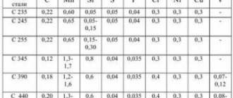
High alloy steels
High-alloy steels have electrical resistivity several times higher than carbon and low-alloy steels. According to the table, it can be seen that at a temperature of 20°C its value is (30...86)·10 -8 Ohm·m.
At a temperature of 1300°C, the resistance of high- and low-alloy steels becomes almost the same and does not exceed 131·10 -8 Ohm·m.
Electrical resistivity of high-alloy steels ρe·10 8 , Ohm m
| steel grade | 20 | 100 | 300 | 500 | 700 | 900 | 1100 | 1300 |
| G13 | 68,3 | 75,6 | 93,1 | 95,2 | 114,7 | 123,8 | 127 | 130,8 |
| G20H12F | 72,3 | 79,2 | 91,2 | 101,5 | 109,2 | — | — | — |
| G21X15T | — | 82,4 | 95,6 | 104,5 | 112 | 119,2 | — | — |
| Х13Н13К10 | — | 90 | 100,8 | 109,6 | 115,4 | 119,6 | — | — |
| Х19Н10К47 | — | 90,5 | 98,6 | 105,2 | 110,8 | — | — | — |
| P18 | 41,9 | 47,2 | 62,7 | 81,5 | 103,7 | 117,3 | 123,6 | 128,1 |
| EH12 | 31 | 36 | 53 | 75 | 97 | 119 | — | — |
| 40Х10С2М (EI107) | 86 | 91 | 101 | 112 | 122 | — | — | — |
What does it depend on
Resistance depends on temperature. It increases when the thermometer rises. This is explained by physicists in such a way that as the temperature increases, atomic vibrations in the crystalline conductor lattice increase. This prevents free electrons from moving around.
Note! As for semiconductors and dielectrics, the value decreases due to the fact that the structure of the concentration of charging carriers increases.
Temperature dependence as the main property of conductive resistance
What do resistivity numbers mean?
In order to be able to compare the resistivity of different materials, from products such as copper and aluminum to other metals and substances including bismuth, brass and even semiconductors, it is necessary to use a standard measurement.
The unit of resistivity in the International System of Units (SI) is Ohm m.
The SI unit of resistivity is equal to the resistivity of a substance such that a homogeneous conductor 1 m long with a cross-sectional area of 1 m2, made from this substance, has a resistance of 1 ohm. Accordingly, the resistivity of an arbitrary substance, expressed in SI units, is numerically equal to the resistance of a section of an electrical circuit made of a given substance with a length of 1 m and a cross-sectional area of 1 m2
Temperature coefficient values for some metals
From the formula for the temperature coefficient of resistance we determine rt:
Example 6. Determine the resistance of an iron wire heated to 200°C, if its resistance at 0°C was 100 Ohms.
Example 7. A resistance thermometer made of platinum wire in a room with a temperature of 15°C had a resistance of 20 ohms. The thermometer was placed in the oven and after some time its resistance was measured. It turned out to be equal to 29.6 Ohms. Determine the temperature in the oven.
Resistivity table for common conductors
The table below shows resistivity values for various materials, particularly metals used for electrical conductivity.
Resistivity indicators are given for such “popular” materials as copper, aluminum, nichrome, steel, lead, gold and others.
MaterialResistivity, ρ, at 20 °C (Ohm m)Source
| Brass | ~0.6 – 0.9 x 10⁻⁷ | |
| Silver | 1.59×10⁻⁸ | [3][4] |
| Copper | 1.68×10⁻⁸ | [5][6] |
| Burnt copper | 1.72×10⁻⁸ | [7] |
| Gold | 2.44×10⁻⁸ | [3] |
| Aluminum | 2.65×10⁻⁸ | [3] |
| Calcium | 3.36×10⁻⁸ | |
| Tungsten | 5.60×10⁻⁸ | [3] |
| Zinc | 5.90×10⁻⁸ | |
| Cobalt | 6.24×10⁻⁸ | |
| Nickel | 6.99×10⁻⁸ | |
| Ruthenium | 7.10×10⁻⁸ | |
| Lithium | 9.28×10⁻⁸ | |
| Iron | 9.70×10⁻⁸ | [3] |
| Platinum | 1.06×10⁻⁷ | [3] |
| Tin | 1.09×10⁻⁷ | |
| Tantalum | 1.3×10⁻⁷ | |
| Gallium | 1.40×10⁻⁷ | |
| Niobium | 1.40×10⁻⁷ | [8] |
| Carbon steel (1010) | 1.43×10⁻⁷ | [9] |
| Lead | 2.20×10⁻⁷ | [2][3] |
| Galinstan | 2.89×10⁻⁷ | [10] |
| Titanium | 4.20×10⁻⁷ | |
| Electrical steel | 4.60×10⁻⁷ | [11] |
| Manganin (alloy) | 4.82×10⁻⁷ | [2] |
| Constantan (alloy) | 4.90×10⁻⁷ | [2] |
| Stainless steel | 6.90×10⁻⁷ | |
| Mercury | 9.80×10⁻⁷ | [2] |
| Manganese | 1.44×10⁻⁶ | |
| Nichrome (alloy) | 1.10×10⁻⁶ | [2][3] |
| Carbon (amorphous) | 5×10⁻⁴ — 8×10⁻⁴ | [3] |
| Carbon (graphite) parallel-basal plane | 2.5×10⁻⁶ — 5.0×10⁻⁶ | |
| Carbon (graphite) perpendicular-basal plane | 3×10⁻³ | |
| Gallium arsenide | 10−3 to 108 | |
| Germanium | 4.6×10⁻¹ | [3][4] |
| Sea water | 2.1×10⁻¹ | |
| Swimming pool water | 3.3×10⁻¹ — 4.0×10⁻¹ | |
| Drinking water | 2×101 — 2×10³ | |
| Silicon | 2.3×10³ | [2][3] |
| Wood (wet) | 103 — 104 | |
| Deionized water | 1.8×10⁵ | |
| Glass | 1011 — 1015 | [3][4] |
| Carbon (diamond) | 1012 | |
| Hard rubber | 1013 | [3] |
| Air | 109 — 1015 | |
| Wood (dry) | 1014 — 1016 | |
| Sulfur | 1015 | [3] |
| Fused quartz | 7.5×10¹⁷ | [3] |
| PAT | 1021 | |
| Teflon | 1023 — 1025 |
It can be seen that the resistivity of copper and the resistivity of brass are both low, and considering their cost relative to silver and gold, they become cost-effective materials to use for many wires. Copper's resistivity and ease of use have led to it being widely used as a conductor material on printed circuit boards.
Occasionally, aluminum and especially copper are used due to their low resistivity. Most wires used for interconnection today are made of copper because it provides low resistivity at an affordable cost.
The resistivity of gold is also important because gold is used in some critical applications despite its cost. Gold plating is often found on high quality low current connectors where it provides the lowest contact resistance. The gold coating is very thin, but even so it is able to provide the required characteristics of the connectors.
Silver has a very low level of resistivity, but is not widely used due to its cost and because it tarnishes, which can result in higher contact resistance.
However, it is used in some radio transmitter coils where silver's low electrical resistivity reduces losses. When used for such purposes, silver was usually applied only to the existing copper wire. Coating the wire with silver allowed for significant cost savings compared to solid silver wire without significantly compromising performance.
It will be interesting➡ Voltage control relay
Other materials in the electrical resistivity table may not have such obvious uses. Tantalum appears in the table because it is used in capacitors—nickel and palladium are used in the end connections of many surface mount components such as capacitors.
Quartz finds its main application as a piezoelectric resonant element. Quartz crystals are used as frequency-determining elements in many oscillators, where the high Q value allows for very frequency-stable circuits. They are similarly used in high efficiency filters. Quartz has a very high level of resistivity and is not a good conductor of electricity, meaning it is classified as a dielectric.
Types of resistivity
Since resistance happens:
- active - or ohmic, resistive - resulting from the expenditure of electricity on heating the conductor (metal) when an electric current passes through it, and
- reactive - capacitive or inductive - which occurs from the inevitable losses due to the creation of any changes in the current passing through the conductor of electric fields, then the resistivity of the conductor comes in two varieties:
- Specific electrical resistance to direct current (having a resistive nature) and
- Specific electrical resistance to alternating current (having a reactive nature).
Here, type 2 resistivity is a complex value; it consists of two TC components - active and reactive, since resistive resistance always exists when current passes, regardless of its nature, and reactive resistance occurs only with any change in current in the circuits. In DC circuits, reactance occurs only during transient processes that are associated with turning on the current (change in current from 0 to nominal) or turning off (difference from nominal to 0). And they are usually taken into account only when designing overload protection.
In alternating current circuits, the phenomena associated with reactance are much more diverse. They depend not only on the actual passage of current through a certain cross section, but also on the shape of the conductor, and the dependence is not linear.
The fact is that alternating current induces an electric field both around the conductor through which it flows and in the conductor itself. And from this field, eddy currents arise, which give the effect of “pushing” the actual main movement of charges, from the depths of the entire cross-section of the conductor to its surface, the so-called “skin effect” (from skin - skin). It turns out that eddy currents seem to “steal” its cross-section from the conductor. The current flows in a certain layer close to the surface, the remaining thickness of the conductor remains unused, it does not reduce its resistance, and there is simply no point in increasing the thickness of the conductors. Especially at high frequencies. Therefore, for alternating current, resistance is measured in such sections of conductors where its entire section can be considered near-surface. Such a wire is called thin; its thickness is equal to twice the depth of this surface layer, where eddy currents displace the useful main current flowing in the conductor.
Of course, reducing the thickness of round wires does not exhaust the effective conduction of alternating current. The conductor can be thinned, but at the same time made flat in the form of a tape, then the cross-section will be higher than that of a round wire, and accordingly, the resistance will be lower. In addition, simply increasing the surface area will have the effect of increasing the effective cross-section. The same can be achieved by using stranded wire instead of single-core; moreover, stranded wire is more flexible than single-core wire, which is often valuable. On the other hand, taking into account the skin effect in wires, it is possible to make the wires composite by making the core from a metal that has good strength characteristics, for example, steel, but low electrical characteristics. In this case, an aluminum braid is made over the steel, which has a lower resistivity.
In addition to the skin effect, the flow of alternating current in conductors is affected by the excitation of eddy currents in surrounding conductors. Such currents are called induction currents, and they are induced both in metals that do not play the role of wiring (load-bearing structural elements), and in the wires of the entire conductive complex - playing the role of wires of other phases, neutral, grounding.
All of these phenomena occur in all electrical structures, making it even more important to have a comprehensive reference for a wide variety of materials.
Resistivity for conductors is measured with very sensitive and precise instruments, since metals with the lowest resistance are selected for wiring - on the order of ohms * 10 -6 per meter of length and sq. m. mm. sections. To measure the specific insulation resistance, you need instruments, on the contrary, that have ranges of very large resistance values - usually megohms. It is clear that conductors must conduct well, and insulators must insulate well.
Concept of electrical resistance of a conductor
The classical definition explains electric current by the movement of “free” (valence) electrons. It is provided by the electric field created by the source. Movement in the metal is hampered not only by the normal components of the crystal lattice, but also by defective areas, impurities, and inhomogeneous areas. During collisions with obstacles, due to the transition of momentum into thermal energy, the temperature increases.
A good example is heating water with a boiler.
In gases, electrolytes and other materials the physics of the phenomenon is somewhat different. Linear relationships are observed in metals and other conductors. The basic relationships are expressed by the well-known formula of Ohm's law:
R (electrical resistance) = U (voltage) / I (current).
For convenience, the inverse quantity, conductivity (G = 1/R), is often used. It denotes the ability of a certain material to pass current with certain losses.
To simplify, the example of a water pipe is sometimes used. A moving fluid is an analogue of a current. Pressure is the equivalent of voltage. By decreasing (increasing) the cross section or position of the locking device, the conditions of movement are determined. In a similar way, the basic parameters of electrical circuits are changed using resistance (R).
For your information. The amount of liquid passing per unit time through the control section of the pipe is the equivalent of electrical power.
Temperature dependence ρ(T)
For most materials, numerous experiments have been carried out to measure resistivity values. Data for most conductors can be found in reference tables.
Specific resistance of metals and alloys, Ohm*mm2/m
(at T = 20C)
| Silver | 0,016 | Bronze (alloy) | 0,1 |
| Copper | 0,017 | Tin | 0,12 |
| Gold | 0,024 | Steel (alloy) | 0,12 |
| Aluminum | 0,028 | Lead | 0,21 |
| Iridium | 0,047 | Nickelin (alloy) | 0,42 |
| Molybdenum | 0,054 | Manganin (alloy) | 0,45 |
| Tungsten | 0,055 | Constantan (alloy) | 0,48 |
| Zinc | 0,06 | Titanium | 0,58 |
| Brass (alloy) | 0,071 | Mercury | 0,958 |
| Nickel | 0,087 | Nichrome (alloy) | 1,1 |
| Platinum | 0,1 | Bismuth | 1,2 |
Most often, the values of ρ are given at normal, that is, room temperature 20C. But it turned out that with increasing temperature, the resistivity increases linearly in accordance with the formula:
$ ρ(T) = ρ0 * (1 + α*T)$ (6),
where: ρ is the resistivity of the conductor at a temperature of 0C, α is the temperature coefficient of resistivity, which also has its own individual meaning for each substance. From formula (6) it follows that the coefficient α has dimension or .
In accordance with the Joule-Lenz law, when an electric current flows, heat is released, which means the temperature of the conductor increases. In addition, depending on the area of application, electrical devices can operate at both low (minus) and high temperatures. For accurate calculations of electrical circuits, it is necessary to take into account the dependence ρ(T). The value of α for a specific material can be found in reference literature.
S=(π?d^2)/4=0.78?d^2≈0.8?d^2
- where d is the diameter of the wire.
You can measure the diameter of the wire with a micrometer or caliper, but if you don’t have them on hand, you can tightly wrap about 20 turns of wire around a pen (pencil), then measure the length of the wound wire and divide by the number of turns.
To determine the cable length needed to achieve the required resistance, you can use the formula:
1. If the data for the wire is not in the table, then some average value is taken. As an example, a nickel wire with a diameter of 0.18 mm, the cross-sectional area is approximately 0.025 mm2, the resistance of one meter is 18 Ohms, and the permissible current is 0.075 A.
2.The data in the last column, for a different current density, must be changed. For example, with a current density of 6 A/mm2, the value must be doubled.
Example 1
. Let's find the resistance of 30 m of copper wire with a diameter of 0.1 mm.
Solution
. Using the table, we take the resistance of 1 m of copper wire, which is equal to 2.2 Ohms. This means that the resistance of 30 m of wire will be R = 30.2.2 = 66 Ohms.
The calculation using the formulas will look like this: cross-sectional area: s = 0.78.0.12 = 0.0078 mm2. Since the resistivity of copper is ρ = 0.017 (Ohm.mm2)/m, we get R = 0.017.30/0.0078 = 65.50 m.
Example 2
. How much manganin wire with a diameter of 0.5 mm is needed to make a rheostat with a resistance of 40 Ohms?
Solution
. Using the table, we select the resistance of 1 m of this wire: R = 2.12 Ohm: To make a rheostat with a resistance of 40 Ohms, you need a wire whose length is l = 40/2.12 = 18.9 m.
The calculation using the formulas will look like this. Cross-sectional area of the wire s = 0.78.0.52 = 0.195 mm2. Wire length l = 0.195.40/0.42 = 18.6 m.
Despite the fact that this topic may seem completely banal, in it I will answer one very important question about calculating voltage loss and calculating short-circuit currents. I think this will be the same discovery for many of you as it was for me.
I recently studied one very interesting GOST:
GOST R 50571.5.52-2011 Low-voltage electrical installations. Part 5-52. Selection and installation of electrical equipment. Electrical wiring.
This document provides a formula for calculating voltage loss and states:
p is the resistivity of conductors under normal conditions, taken equal to the resistivity at temperature under normal conditions, that is, 1.25 resistivity at 20 °C, or 0.0225 Ohm mm 2 /m for copper and 0.036 Ohm mm 2 / m for aluminum;
I didn’t understand anything =) Apparently, when calculating voltage loss and when calculating short-circuit currents, we must take into account the resistance of the conductors, as under normal conditions.
It is worth noting that all table values are given at a temperature of 20 degrees.
What are normal conditions? I thought 30 degrees Celsius.
Let's remember physics and calculate at what temperature the resistance of copper (aluminum) will increase by 1.25 times.
R0 – resistance at 20 degrees Celsius;
R1 - resistance at T1 degrees Celsius;
T0 - 20 degrees Celsius;
α=0.004 per degree Celsius (copper and aluminum are almost the same);
Т1=(1.25-1)/ α+Т0=(1.25-1)/0.004+20=82.5 degrees Celsius.
As you can see, this is not 30 degrees at all. Apparently, all calculations must be performed at the maximum permissible cable temperatures. The maximum operating temperature of the cable is 70-90 degrees depending on the type of insulation.
To be honest, I don’t agree with this, because... this temperature corresponds to a practically emergency mode of the electrical installation.
In my programs, I set the resistivity of copper as 0.0175 Ohm mm 2 /m, and for aluminum as 0.028 Ohm mm 2 /m.
If you remember, I wrote that in my program for calculating short-circuit currents, the result is approximately 30% less than the table values. There, the phase-zero loop resistance is calculated automatically. I tried to find the error, but I couldn't. Apparently, the inaccuracy of the calculation lies in the resistivity used in the program. And everyone can ask about resistivity, so there should be no questions about the program if you indicate the resistivity from the above document.
But I will most likely have to make changes to the programs for calculating voltage losses. This will result in a 25% increase in the calculation results. Although in the ELECTRIC program, the voltage losses are almost the same as mine.
If this is your first time on this blog, then you can see all my programs on the page
In your opinion, at what temperature should voltage losses be calculated: at 30 or 70-90 degrees? Are there regulations that will answer this question?
One of the physical quantities used in electrical engineering is electrical resistivity. When considering the resistivity of aluminum, it should be remembered that this value characterizes the ability of a substance to prevent the passage of electric current through it.
Electrical resistivity
Further research made it possible to establish a connection between the value of electrical resistance and its basic geometric dimensions. It turned out that the resistance of the conductor is directly proportional to the length of the conductor L and inversely proportional to the cross-sectional area of the conductor S.
This functional relationship is well described by the following formula:
$ R = ρ *{ Lover S} $ (4)
The constant value ρ for each substance was called resistivity. The value of this parameter depends on the density of the substance, its crystal structure, atomic structure and other internal characteristics of the substance. From formula (4) you can obtain a formula for calculating resistivity if experimental values for R, L and S are available:
$ ρ = R*{ Sover L } $ (5)
For most known substances, measurements were made and entered into reference tables of electrical resistance of conductors.
Specific resistance of metals, Ohm*mm2/m
(at T = 20C)
| Silver | 0,016 | Bronze (alloy) | 0,1 |
| Copper | 0,017 | Tin | 0,12 |
| Gold | 0,024 | Steel (alloy) | 0,12 |
| Aluminum | 0,028 | Lead | 0,21 |
| Iridium | 0,047 | Nickelin (alloy) | 0,42 |
| Molybdenum | 0,054 | Manganin (alloy) | 0,45 |
| Tungsten | 0,055 | Constantan (alloy) | 0,48 |
| Zinc | 0,06 | Titanium | 0,58 |
| Brass (alloy) | 0,071 | Mercury | 0,958 |
| Nickel | 0,087 | Nichrome (alloy) | 1,1 |
| Platinum | 0,1 | Bismuth | 1,2 |
It was experimentally discovered that as the temperature decreases, the resistance of metals decreases. When approaching the temperature of absolute zero, which is -273C, the resistance of some metals tends to zero. This phenomenon is called superconductivity. Atoms and molecules seem to “froze”, stop any movement and offer no resistance to the flow of electrons.
Iron as a conductor in electrical engineering
Iron is the most common metal in nature and technology (after hydrogen, which is also a metal). It is the cheapest and has excellent strength characteristics, therefore it is used everywhere as the basis for the strength of various structures.
In electrical engineering, iron is used as a conductor in the form of flexible steel wires where physical strength and flexibility are needed, and the required resistance can be achieved through the appropriate cross-section.
Having a table of resistivities of various metals and alloys, you can calculate the cross-sections of wires made from different conductors.
As an example, let's try to find the electrically equivalent cross-section of conductors made of different materials: copper, tungsten, nickel and iron wire. Let's take aluminum wire with a cross-section of 2.5 mm as the initial one.
We need that over a length of 1 m the resistance of the wire made of all these metals is equal to the resistance of the original one. The resistance of aluminum per 1 m length and 2.5 mm section will be equal to
, where R is the resistance, ρ is the resistivity of the metal from the table, S is the cross-sectional area, L is the length.
Substituting the original values, we get the resistance of a meter-long piece of aluminum wire in ohms.
After this, let us solve the formula for S
, we will substitute the values from the table and obtain the cross-sectional areas for different metals.
So,
Since the resistivity in the table is measured on a wire 1 m long, in microohms per 1 mm2 section, then we got it in microohms. To get it in ohms, you need to multiply the value by 10-6. But we don’t necessarily need to get the number ohm with 6 zeros after the decimal point, since we still find the final result in mm2.
- Copper
- Tungsten
- Nikelin
- Iron
It will be interesting➡ Choke for fluorescent lamps
As you can see, the resistance of the iron is quite high, the wire is thick.
But there are materials for which it is even greater, for example, nickel or constantan.
Why do metals have the lowest resistivities?
From the table above it can be seen that metals have the lowest resistivity values: silver, copper, gold, aluminum, etc. This property of metals is associated with a high concentration of free electrons, “not tied” to a specific atom, but wandering in the space of the crystal lattice. Voltage applied to the ends of a conductor creates an electric field that acts on the electrons, causing them to move in concert in the same direction.
Rice. 2. Electric current in metals, free electrons.
Silver has the lowest ρ value - 0.016 Ohm*mm2/m. But for widespread, mass use in power supply networks and equipment, this metal is not used due to its too high price. Silver is used to create the most critical contacts in special electrical devices. The following table shows the resistivity values of metals and alloys, commonly used metals in electrical engineering:
Table
Specific resistances of metals, Ohm*mm2/m
(at T = 200C)
| Silver | 0,016 | Bronze (alloy) | 0,1 |
| Copper | 0,017 | Tin | 0,12 |
| Gold | 0,024 | Steel (alloy) | 0,12 |
| Aluminum | 0,028 | Lead | 0,21 |
| Iridium | 0,047 | Nickelin (alloy) | 0,42 |
| Molybdenum | 0,054 | Manganin (alloy) | 0,45 |
| Tungsten | 0,055 | Constantan (alloy) | 0,48 |
| Zinc | 0,06 | Titanium | 0,58 |
| Brass (alloy) | 0,071 | Mercury | 0,958 |
| Nickel | 0,087 | Nichrome (alloy) | 1,1 |
| Platinum | 0,1 | Bismuth | 1,2 |
The most popular in electrical engineering are copper and aluminum. Copper and copper alloys are used to make cable products and shunts - parts that limit large currents through measuring instruments.
Electrical tomography
Electrical prospecting studies the near-surface geological environment and is used to search for ore and non-metallic minerals and other objects based on the study of various artificial electric and electromagnetic fields. A special case of electrical prospecting is electrical tomography (Electrical Resistivity Tomography), a method for determining the properties of rocks by their resistivity.
The essence of the method is that at a certain position of the electric field source, voltage measurements are taken on various probes, then the field source is moved to another location or switched to another source and the measurements are repeated. Field sources and field receiver probes are placed on the surface and in wells.
Then the obtained data is processed and interpreted using modern computer processing methods, which make it possible to visualize information in the form of two-dimensional and three-dimensional images.
Being a very accurate search method, electrical tomography provides invaluable assistance to geologists, archaeologists and paleozoologists.
Determining the form of occurrence of mineral deposits and the boundaries of their distribution (contouring) makes it possible to identify the occurrence of vein deposits of minerals, which significantly reduces the costs of their subsequent development.
For archaeologists, this search method provides valuable information about the location of ancient burials and the presence of artifacts in them, thereby reducing excavation costs.
Paleozoologists use electrical tomography to search for the fossilized remains of ancient animals; the results of their work can be seen in natural science museums in the form of stunning reconstructions of the skeletons of prehistoric megafauna.
In addition, electrical tomography is used during the construction and subsequent operation of engineering structures: high-rise buildings, dams, dikes, embankments and others.
Effect of temperature on resistivity
In reference books, the values of ρ of metals are given at room temperature 200C. But experiments have shown that the dependence ρ(T) is linear and is described by the formula:
$ ρ(T) = ρ0 * (1 + α*T)$ (3),
where: ρ0 is the resistivity of the conductor at a temperature of 00C, α is the temperature coefficient of resistance, which is also individual for each substance. Values of α obtained experimentally can be found in reference books. Below are α values for some metals:
- Silver - 0.0035;
- Copper - 0.004;
- Aluminum - 0.004;
- Iron - 0.0066;
- Platinum - 0.0032;
- Tungsten - 0.0045.
Thus, as the temperature increases, the resistance of metals increases. This is explained by the fact that with increasing temperature, the number of defects in the crystal lattice increases due to more intense thermal vibrations of the ions, which inhibit the electron current.
Temperature dependence of resistivity of metals.
As the metal temperature approaches absolute zero, the resistivity drops sharply to zero. This phenomenon is called superconductivity, and materials that exhibit this ability are called superconductors. This effect was discovered in 1911 by the Dutch physicist Kamerlingh Onnes. In his experiment, the resistivity of mercury decreased to zero at 4.10K.
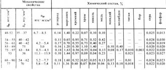
Carbon steels
Carbon steels at room temperature, as already mentioned, have low electrical resistivity due to their high iron content. At 20°C, the value of their resistivity is in the range from 13·10 -8 (for steel 08KP) to 20·10 -8 Ohm m (for U12).
When heated to temperatures above 1000°C, the ability of carbon steels to conduct electric current is greatly reduced. The resistance value increases by an order of magnitude and can reach a value of 130·10 -8 Ohm·m.
Electrical resistivity of carbon steels ρe·10 8 , Ohm m
| 15,9 | 16 | 17 | 18,4 | |||
| 20 | 13 | 14,2 | 16,9 | 17,1 | 18 | 19,6 |
| 50 | 14,7 | 15,9 | 18,7 | 18,9 | 19,8 | 21,6 |
| 100 | 17,8 | 19 | 21,9 | 22,1 | 23,2 | 25,2 |
| 150 | 21,3 | 22,4 | 25,4 | 25,7 | 26,8 | 29 |
| 200 | 25,2 | 26,3 | 29,2 | 29,6 | 30,8 | 33,3 |
| 250 | 29,5 | 30,5 | 33,4 | 33,9 | 35,1 | 37,9 |
| 300 | 34,1 | 35,2 | 38,1 | 38,7 | 39,8 | 43 |
| 350 | 39,3 | 40,2 | 43,2 | 43,8 | 45 | 48,3 |
| 400 | 44,8 | 45,8 | 48,7 | 49,3 | 50,5 | 54 |
| 450 | 50,9 | 51,8 | 54,6 | 55,3 | 56,5 | 60 |
| 500 | 57,5 | 58,4 | 60,1 | 61,9 | 62,8 | 66,5 |
| 550 | 64,8 | 65,7 | 68,2 | 68,9 | 69,9 | 73,4 |
| 600 | 72,5 | 73,4 | 75,8 | 76,6 | 77,2 | 80,2 |
| 650 | 80,7 | 81,6 | 83,7 | 84,4 | 85,2 | 87,8 |
| 700 | 89,8 | 90,5 | 92,5 | 93,2 | 93,5 | 96,4 |
| 750 | 100,3 | 101,1 | 105 | 107,9 | 110,5 | 113 |
| 800 | 107,3 | 108,1 | 109,4 | 111,1 | 112,9 | 115 |
| 850 | 110,4 | 111,1 | 111,8 | 113,1 | 114,8 | 117,6 |
| 900 | 112,4 | 113 | 113,6 | 114,9 | 116,4 | 119,6 |
| 950 | 114,2 | 114,8 | 115,2 | 116,6 | 117,8 | 121,2 |
| 1000 | 116 | 116,5 | 116,7 | 117,9 | 119,1 | 122,6 |
| 1050 | 117,5 | 117,9 | 118,1 | 119,3 | 120,4 | 123,8 |
| 1100 | 118,9 | 119,3 | 119,4 | 120,7 | 121,4 | 124,9 |
| 1150 | 120,3 | 120,7 | 120,7 | 122 | 122,3 | 126 |
| 1200 | 121,7 | 122 | 121,9 | 123 | 123,1 | 127,1 |
| 1250 | 123 | 123,3 | 122,9 | 124 | 123,8 | 128,2 |
| 1300 | 124,1 | 124,4 | 123,9 | — | 124,6 | 128,7 |
| 1350 | 125,2 | 125,3 | 125,1 | — | 125 | 129,5 |
Properties of resistive materials
The resistivity of a metal depends on temperature. Their values are usually given for room temperature (20°C). The change in resistivity as a result of a change in temperature is characterized by a temperature coefficient.
For example, thermistors (thermistors) use this property to measure temperature. On the other hand, in precision electronics, this is a rather undesirable effect. Metal film resistors have excellent temperature stability properties. This is achieved not only due to the low resistivity of the material, but also due to the mechanical design of the resistor itself.
Many different materials and alloys are used in the manufacture of resistors. Nichrome (an alloy of nickel and chromium), due to its high resistivity and resistance to oxidation at high temperatures, is often used as a material for making wirewound resistors. Its disadvantage is that it cannot be soldered. Constantan, another popular material, is easy to solder and has a lower temperature coefficient.
Electrical resistance of other metals
Current resistance: formula
In addition to copper and aluminum, other metals and alloys are used in electrical engineering:
- Iron. Steel has a higher resistivity, but is stronger than copper and aluminum. Steel strands are woven into cables designed to be laid through the air. The resistance of iron is too high to transmit electricity, so the core cross-sections are not taken into account when calculating the cross-section. In addition, it is more refractory, and leads are made from it for connecting heaters in high-power electric furnaces;
- Nichrome (an alloy of nickel and chromium) and fechral (iron, chromium and aluminum). They have low conductivity and refractoriness. Wirewound resistors and heaters are made from these alloys;
- Tungsten. Its electrical resistance is high, but it is a refractory metal (3422 °C). It is used to make filaments in electric lamps and electrodes for argon-arc welding;
- Constantan and manganin (copper, nickel and manganese). The resistivity of these conductors does not change with changes in temperature. Used in high-precision devices for the manufacture of resistors;
- Precious metals – gold and silver. They have the highest specific conductivity, but due to their high price, their use is limited.
High conductivity materials
The most widespread materials of high conductivity include copper and aluminum (Superconducting materials, which have a typical resistance 10-20 times lower than ordinary conductive materials (metals), are discussed in the section Superconductivity).
Copper
The advantages of copper, which ensure its widespread use as a conductor material, are as follows:
- low resistivity;
- sufficiently high mechanical strength;
- corrosion resistance is satisfactory in most applications;
- good workability: copper is rolled into sheets, strips and drawn into wire, the thickness of which can be increased to thousandths of a millimeter;
- relative ease of soldering and welding.
Copper is most often obtained by processing sulfide ores. After a series of ore smelting and roasting with intense blasting, copper intended for electrical purposes must undergo a process of electrolytic purification.
Copper grades M1 and M0 are most often used as conductor material. M1 grade copper contains 99.9% Cu, and in the total amount of impurities (0.1%) oxygen should be no more than 0.08%. The presence of oxygen in copper worsens its mechanical properties. The best mechanical properties are found in M0 grade copper, which contains no more than 0.05% impurities, including no more than 0.02% oxygen.
Copper is a relatively expensive and scarce material, so it is increasingly being replaced by other metals, especially aluminum.
In some cases, alloys of copper with tin, silicon, phosphorus, beryllium, chromium, magnesium, and cadmium are used. Such alloys, called bronzes, with the correct composition, have significantly higher mechanical properties than pure copper.
Aluminum
Aluminum is the second most important conductor material after copper. This is the most important representative of the so-called light metals: the density of cast aluminum is about 2.6, and rolled aluminum is 2.7 Mg/m3. Thus, aluminum is approximately 3.5 times lighter than copper. The temperature coefficient of expansion, specific heat capacity and heat of fusion of aluminum are greater than those of copper. Due to the high values of specific heat capacity and heat of fusion, heating aluminum to the melting point and transferring it to a molten state requires more heat than heating and melting the same amount of copper, although the melting point of aluminum is lower than that of copper.
Aluminum has lower properties compared to copper - both mechanical and electrical. With the same cross-section and length, the electrical resistance of an aluminum wire is 1.63 times greater than that of a copper wire. It is very important that aluminum is less scarce than copper.
For electrical purposes, aluminum containing no more than 0.5% impurities, grade A1, is used. Even purer AB00 grade aluminum (no more than 0.03% impurities) is used for the manufacture of aluminum foil, electrodes and housings of electrolytic capacitors. Aluminum of the highest purity AB0000 has an impurity content of no more than 0.004%. Additives of Ni, Si, Zn or Fe at a content of 0.5% reduce the γ of annealed aluminum by no more than 2-3%. A more noticeable effect is exerted by Cu, Ag and Mg impurities, which, at the same mass content, reduce γ aluminum by 5-10%. Ti and Mn greatly reduce the electrical conductivity of aluminum.
Aluminum oxidizes very actively and becomes covered with a thin oxide film with high electrical resistance. This film protects the metal from further corrosion.
It will be interesting➡ PNP transistor
Aluminum alloys have increased mechanical strength. An example of such an alloy is Aldrey, containing 0.3-0.5% Mg, 0.4-0.7% Si and 0.2-0.3% Fe. In aldrey, the Mg2Si compound is formed, which imparts high mechanical properties to the alloy.
Iron and steel
Iron (steel), as the cheapest and most accessible metal, which also has high mechanical strength, is of great interest for use as a conductor material. However, even pure iron has a significantly higher resistivity compared to copper and aluminum; ρ steel, i.e. iron mixed with carbon and other elements is even higher. Ordinary steel has low corrosion resistance: even at normal temperatures, especially in conditions of high humidity, it quickly rusts; As the temperature rises, the corrosion rate increases sharply. Therefore, the surface of steel wires must be protected by a layer of more resistant material. Zinc coating is usually used for this purpose.
In some cases, to reduce the consumption of non-ferrous metals, the so-called bimetal is used. It is steel coated on the outside with a layer of copper, with both metals connected to each other firmly and continuously.
Sodium
Sodium metal is a very promising conductor material. Sodium can be obtained by electrolysis of molten sodium chloride NaCl in virtually unlimited quantities. From a comparison of the properties of sodium with the properties of other conductor metals, it is clear that the resistivity of sodium is approximately 2.8 times greater than ρ of copper and 1.7 times greater than ρ of aluminum, but due to the extremely low density of sodium (its density is almost 9 times less than the density of copper), a wire made of sodium for a given conductivity per unit length should be significantly lighter than a wire made of any other metal. However, sodium is extremely active chemically (it oxidizes intensely in air and reacts violently with water), which is why the sodium wire must be protected with a sealing sheath. The sheath must give the wire the necessary mechanical strength, since sodium is very soft and has a low tensile strength during deformation.
Steel Specifications
Before considering the resistivity of steel in detail, you should familiarize yourself with its basic physical and mechanical properties. Due to its qualities, this material is widely used in the manufacturing sector and other areas of people’s lives and activities.
Steel is an alloy of iron and carbon, contained in an amount not exceeding 1.7%. In addition to carbon, steel contains a certain amount of impurities - silicon, manganese, sulfur and phosphorus. In terms of its qualities, it is much better than cast iron; it can easily be hardened, forged, rolled and other types of processing. All types of steels are characterized by high strength and ductility.
According to its purpose, steel is divided into structural, instrumental, and also with special physical properties. Each of them contains a different amount of carbon, thanks to which the material acquires certain specific qualities, for example, heat resistance, heat resistance, resistance to rust and corrosion.
A special place is occupied by electrical steels, produced in sheet format and used in the production of electrical products. To obtain this material, silicon is doped, which can improve its magnetic and electrical properties.
In order for electrical steel to acquire the necessary characteristics, certain requirements and conditions must be met. The material must be easily magnetized and remagnetized, that is, have high magnetic permeability. Such steels have good , and their magnetization reversal is carried out with minimal losses.
The dimensions and weight of magnetic cores and windings, as well as the efficiency of transformers and their operating temperature depend on compliance with these requirements. The fulfillment of the conditions is influenced by many factors, including the resistivity of steel.
What is the resistance of copper wire
In metals, a current is formed when an electric field appears. It “forces” electrons to move in an orderly manner, in one direction. Electrons from the distant orbits of an atom, weakly held by the nucleus, form a current.
Copper wires
As negative particles pass through the crystal lattice of copper molecules, they collide with atoms and other electrons. There is an obstacle or resistance to the directional movement of particles.
To evaluate the resistance to current, the value of “electrical resistance” or “electrical impedance” was introduced. It is designated by the letter “R” or “r”. Resistance is calculated using Georg Ohm's formula: R=, where U is the potential difference or voltage acting on a section of the circuit, I is the current strength.
Concept of resistance
Important! The higher the impedance value of a metal, the less current passes through it, and it is copper conductors that are so widespread in electrical engineering due to this property.
Based on Ohm's formula, the magnitude of the current is affected by the applied voltage at a constant R. But the resistance of copper wires varies depending on their physical characteristics and operating conditions.
Wire resistance
Electrical resistance is the main characteristic of conductor materials. Depending on the area of application of the conductor, the value of its resistance can play both a positive and negative role in the functioning of the electrical system. Also, the specific application of the conductor may necessitate taking into account additional characteristics, the influence of which in a particular case cannot be neglected.
The nature of resistance
Conductors are pure metals and their alloys. In a metal, atoms fixed in a single “strong” structure have free electrons (the so-called “electron gas”). It is these particles that in this case are the charge carriers. Electrons are in constant, random motion from one atom to another. When an electric field appears (connecting a voltage source to the ends of the metal), the movement of electrons in the conductor becomes ordered. Moving electrons encounter obstacles on their path caused by the peculiarities of the molecular structure of the conductor. When they collide with a structure, charge carriers lose their energy, giving it to the conductor (heating it). The more obstacles a conductive structure creates to charge carriers, the higher the resistance.
As the cross section of the conducting structure increases for one number of electrons, the “transmission channel” will become wider and the resistance will decrease. Accordingly, as the length of the wire increases, there will be more such obstacles and the resistance will increase.
Thus, the basic formula for calculating resistance includes the length of the wire, the cross-sectional area and a certain coefficient that relates these dimensional characteristics to the electrical quantities of voltage and current (1). This coefficient is called resistivity. R= r*L/S (1)
Resistivity
Resistivity is constant and is a property of the substance from which the conductor is made. Units of measurement r - ohm*m. Often the resistivity value is given in ohm*mm sq./m. This is due to the fact that the cross-sectional area of the most commonly used cables is relatively small and is measured in mm2. Let's give a simple example.
Task No. 1. Copper wire length L = 20 m, cross-section S = 1.5 mm. sq. Calculate the wire resistance. Solution: resistivity of copper wire r = 0.018 ohm*mm. sq./m. Substituting the values into formula (1) we get R=0.24 ohms. When calculating the resistance of the power system, the resistance of one wire must be multiplied by the number of wires. If instead of copper you use aluminum with a higher resistivity (r = 0.028 ohm * mm sq. / m), then the resistance of the wires will increase accordingly. For the example above, the resistance will be R = 0.373 ohms (55% more). Copper and aluminum are the main materials for wires. There are metals with lower resistivity than copper, such as silver. However, its use is limited due to its obvious high cost. The table below shows the resistance and other basic characteristics of conductor materials.
Table - main characteristics of conductors
electry.ru
What affects the resistance of a copper wire
The electrical impedance of a copper cable depends on several factors:
- Specific resistance;
- Wire cross-sectional area;
- Wire lengths;
- External temperature.
The last point can be neglected in conditions of domestic use of the cable. A noticeable change in impedance occurs at temperatures above 100°C.
Resistance dependence
Resistivity in the SI system is denoted by the letter ρ. It is defined as the resistance value of a conductor having a cross-section of 1 m2 and a length of 1 m, measured in Ohm ∙ m2. This dimension is inconvenient in electrical calculations, so the unit of measurement Ohm ∙ mm2 is often used.
Important! This parameter is a characteristic of the substance - copper. It does not depend on the shape or cross-sectional area. The purity of the copper, the presence of impurities, the method of making the wire, and the temperature of the conductor are factors that affect the resistivity.
The dependence of the parameter on temperature is described by the following formula: ρt= ρ20[1+ α(t−20°C)]. Here ρ20 is the resistivity of copper at 20°C, α is an empirically found coefficient, from 0°C to 100°C for copper it has a value equal to 0.004 °C-1, t is the temperature of the conductor.
Below is a table of ρ values for different metals at a temperature of 20°C.
Resistivity table
According to the table, copper has a low resistivity, lower only for silver. This ensures good conductivity of the metal.
The thicker the wire, the lower its resistance. The dependence of R of the conductor on the cross-section is called “inversely proportional”.
Important! As the cross-sectional area of the cable increases, it is easier for electrons to pass through the crystal lattice. Therefore, with increasing load and increasing current density, the cross-sectional area should be increased.
An increase in the length of a copper cable entails an increase in its resistance. Impedance is directly proportional to the length of the wire. The longer the conductor, the more atoms there are in the path of free electrons.
conclusions
The last element that affects the resistance of copper is the temperature of the environment. The higher it is, the greater the amplitude of movement of the atoms of the crystal lattice. Thus, they create an additional obstacle for electrons participating in directed movement.
Important! If you lower the temperature to absolute zero, which has a value of 0° K or -273°C, then the opposite effect will be observed - the phenomenon of superconductivity. In this state, the substance has zero resistance.
Temperature correlation
Electrical conductivity
So far, we have considered the resistance of a conductor as the obstacle that the conductor provides to the electric current. But still, current flows through the conductor. Therefore, in addition to resistance (obstacle), the conductor also has the ability to conduct electric current, that is, conductivity.
The more resistance a conductor has, the less conductivity it has, the worse it conducts electric current, and, conversely, the lower the resistance of a conductor, the more conductivity it has, the easier it is for current to pass through the conductor. Therefore, the resistance and conductivity of a conductor are reciprocal quantities.
From mathematics we know that the reciprocal of 5 is 1/5 and, conversely, the reciprocal of 1/7 is 7. Therefore, if the resistance of a conductor is denoted by the letter r, then the conductivity is defined as 1/r. Conductivity is usually symbolized by the letter g.
Electrical conductivity is measured in (1/Ohm) or in siemens.
Example 8. The conductor resistance is 20 ohms. Determine its conductivity.
Example 9. The conductivity of the conductor is 0.1 (1/Ohm). Determine its resistance
If g = 0.1 (1/Ohm), then r = 1 / 0.1 = 10 (Ohm)
Comparison of conductivity of different types of steel
The characteristics of steel depend on its composition and temperature:
- For carbon alloys, the resistance is quite low: it is 0.13-0.2 μOhm/m. The higher the temperature, the greater the value;
- Low-alloy alloys have a higher resistance - 0.2-0.43 μOhm/m;
- High-alloy steels have high resistance - 0.3-0.86 μOhm/m;
- Due to the high chromium content, the resistance of chromium stainless alloys is 0.5-0.6 μOhm/m;
- Chromium-nickel austenitic steels are stainless and, thanks to nickel, have a high resistance of 0.7-0.9 μOhm/m.
Copper ranks second in terms of electrical conductivity: it perfectly passes electric current and is widely used in the manufacture of wires. Aluminum is also used no less often: it is weaker than copper, but cheaper and lighter.
Chromium-nickel austenitic steels
Chromium-nickel austenitic steels are also stainless, but due to the addition of nickel they have a resistivity almost one and a half times higher than that of chromium steels - it reaches a value of (70...90)·10 -8 Ohm·m.
Electrical resistivity of chromium-nickel stainless steels ρe·10 8 , Ohm m
| steel grade | 20 | 100 | 300 | 500 | 700 | 900 | 1100 |
| 12Х18Н9 | — | 74,3 | 89,1 | 100,1 | 109,4 | 114 | — |
| 12Х18Н9Т | 72,3 | 79,2 | 91,2 | 101,5 | 109,2 | — | — |
| 17Х18Н9 | 72 | 73,5 | 92,5 | 103 | 111,5 | 118,5 | — |
| Х18Н11Б | — | 84,6 | 97,6 | 107,8 | 115 | — | — |
| Х18Н9В | 71 | 77,6 | 91,6 | 102,6 | 111,1 | 117,1 | 122 |
| 4Х14НВ2М (ЭИ69) | 81,5 | 87,5 | 100 | 110 | 117,5 | — | — |
| 1Х14Н14В2М (ЭИ257) | — | 82,4 | 95,6 | 104,5 | 112 | 119,2 | — |
| 1x14N18M3T | — | 89 | 100 | 107,5 | 115 | — | — |
| 36Х18Н25С2 (ЭЯ3С) | — | 98,5 | 105,5 | 110 | 117,5 | — | — |
| Х13Н25М2В2 | — | 103 | 112,1 | 118,1 | 121 | — | — |
| Х7Н25 (ЭИ25) | — | — | 109 | 115 | 121 | 127 | — |
| Х2Н35 (ЭИ36) | 87,5 | 92,5 | 103 | 110 | 116 | 120,5 | — |
| H28 | 84,2 | 89,1 | 99,6 | 107,7 | 114,2 | 118,4 | 122,5 |
Active resistance of wires, cables and lines
Due to the fact that alternating current flows unevenly, under the same conditions, alternating and direct current R will be different. As already mentioned, steel electrical wires have a better active R compared to conductors made of non-ferrous metals, which have the same R at any current strength.
On the contrary, the active R of steel electrical cables always depends on the electric current, so DC conductivity is never used in this case. The active R of an electrical cable is determined using the formula: R=l/y*s.
Inductive reactance
Formulas for calculating the conductivity of wires are valid only in a direct current network or in straight conductors at low frequencies. Inductive reactance appears in coils and in high-frequency networks, many times higher than usual. In addition, high frequency current only travels along the surface of the wire. Therefore, it is sometimes coated with a thin layer of silver or Litz wire is used.
Reference. Litz wire is a stranded wire, each core in which is isolated from the rest. This is done to increase surface area and conductivity in high frequency networks.
Copper's resistivity, flexibility, relatively low price and mechanical strength make this metal, along with aluminum, the most common material for making wires.
The essence of the phenomenon
This is a value characteristic of a conductor having a length of 1 meter and a cross-sectional area of 1 square meter/millimeter. It is denoted by the Greek letter ρ. Different materials have different resistivities. At the same time, the resistance of the conductor will change in direct proportion to the length and in inverse proportion to the cross-sectional area. That is, the longer the conductor, the higher it is, but the greater the thickness, the lower it is.
Length
Previous
MiscellaneousWhat is an RCD?
Historical reference
The concept of specific electrical resistance appeared thanks to the works of the famous German physicist Georg Ohm, who theoretically substantiated and, through numerous experiments, proved the connection between the current strength, the electromotive force of the battery and the resistance of all parts of the circuit, thus discovering the law of the elementary electrical circuit, which was then named after him. Ohm studied the dependence of the magnitude of the flowing current on the magnitude of the applied voltage, on the length and shape of the conductor material, as well as on the type of material used as a conducting medium.
At the same time, we must pay tribute to the work of Sir Humphry Davy, an English chemist, physicist and geologist, who was the first to establish the dependence of the electrical resistance of a conductor on its length and cross-sectional area, and also noted the dependence of electrical conductivity on temperature.
Studying the dependence of the flow of electric current on the type of materials, Ohm discovered that each conductive material available to him had some characteristic characteristic of resistance to the flow of current inherent only to it.
It should be noted that in Ohm’s time, one of the most common conductors today - aluminum - had the status of a particularly precious metal, so Ohm limited himself to experiments with copper, silver, gold, platinum, zinc, tin, lead and iron.
Ultimately, Ohm introduced the concept of electrical resistivity of a material as a fundamental characteristic, knowing absolutely nothing about the nature of current flow in metals or the dependence of their resistance on temperature.