A current clamp is a device for measuring electric current without breaking the electrical circuit. That is, to use this tool, you do not need to cut the wire and use probes. As a rule, current clamps are not made as a separate device, but are built into multifunctional devices - multimeters, which can measure many other parameters: voltage, resistance, temperature.
Principle of operation
As the name suggests, TK or Dietze clamps are designed to measure alternating current in a circuit without breaking it. The operation of a current measuring instrument is based on the principle of a simple current transformer. In this case, the primary winding is a bus or cable with the measured current, and the role of the secondary winding is played by the clamp of the clamp, inside of which there is a second multi-turn winding wound on a magnetic core made of ferromagnetic material. The alternating current in the wire (primary coil) creates an alternating magnetic mole, the lines of force of which pass through the secondary winding, exciting an EMF in it, proportional to the magnitude of the current in the first coil. Thus, by measuring the emerging EMF, you can find the current strength in the first coil (wire).
What do clamp meters measure?
Before purchasing this device, you need to decide for what purpose the electrical clamps are intended.
They are a transformer with a connected ammeter. The device itself is the primary winding of the transformer. Placing a conductor inside it helps induce an electric current into the winding due to the resulting electromagnetic field. Then it goes to the secondary winding of the coil, the readings from which are read by an ammeter. The readings of this device are recalculated adjusted for the transformation ratio indicated on it. A transformer does not work with direct current, so the current clamps described are for alternating current.
Clamp meters manufactured today are used for values measured at direct current. A Hall sensor is placed in place of the ammeter, which detects the presence and voltage of the electromagnetic field.
Using these devices, the following measurements are made:
- actual network load;
- the accuracy of readings of various equipment intended for electricity metering, comparing the readings on them with the readings obtained when measuring with clamps;
- power of household and professional electrical appliances.
Current clamps for direct current are more expensive than their counterparts for alternating current, but they are more accurate and have improved quality indicators.
The tool, used in conjunction with a digital multimeter, allows the user to save the user from calculating the desired value, since the device has a built-in calculator.
Design
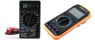
Modern current clamp meters, regardless of manufacturer and modification, contain the following elements: magnetic circuits with a movable bracket-lever, a switch for measurement ranges, a screen, output connectors for probes (in this case, the clamps can be used as a regular multimeter) and a button for fixing current measurements (photo below ).
Figure 1 – TK S-line DT 266 FT
Most modern current meters also include an internal diode bridge transformer. In this case, the terminals of the secondary winding are connected via a shunt. Depending on the range of measured currents, current clamps can be one-handed (for voltages up to 1000 V) or two-handed with additional insulated handles (for voltages from 2 to 10 kV inclusive). Current measuring devices intended for measurements of more than 1 kV have an insulator length of less than 38 cm, and handles of at least 13 cm.
As a rule, the safety category and the maximum measured current are indicated on the device body. For example:
- CAT III 600 V - this means that the device is protected from short-term voltage surges inside the equipment when operating in fixed networks with voltages up to 600 V.
- CATIV 300 V - this means that the device is protected from voltage surges inside primary power supply equipment with voltages up to 300 V. An example of such equipment is a conventional electric meter.
Do it yourself
If a person knows a little about electronics and has a digital multimeter, then he can quickly make an addition to it. To do this, you will need any Hall sensor, they are commercially available, and a ferrite ring.
The ring is split into two parts, a sensor is attached to one end, and wires are soldered to its contacts. The half rings are attached to a clothespin or something similar. The ends of the wires are inserted into the sockets of the multimeter. The device is switched to millivoltmeter mode.
If a conductor through which current flows is placed in a ferrite ring, then some values can be observed on a millivoltmeter. Depending on the sensor used, the conversion factor from magnetic field strength to electrical voltage will be different, but constant for a particular sensor.
Using reference currents you can calibrate the scale. The result is a simple and convenient attachment to the multimeter.
Measurement order
As a rule, using current clamps does not cause any particular difficulties. Before using the tool, you should pay great attention to safety precautions, as mentioned earlier.
How to use clamp meters correctly:
- Set the required range on the switch.
- Press the magnetic circuit opening button.
- Encircle a single conductor in an AC or DC network (if such a possibility is supported by the device).
- Position the current clamps perpendicular to the direction of the wire.
- Take readings from the display.
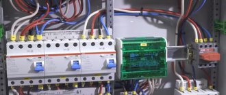
Often the difficulty in using a clamp meter lies in isolating a single conductor: when you try to take readings from a regular cable coming from an outlet, zero should appear on the screen. This happens because the currents of the phase wire and neutral conductor are equal in magnitude and opposite in direction. Consequently, the magnetic fluxes created by them are mutually compensated. If the current readings are different from zero, then this indicates the presence of a current leak in the circuit, the magnitude of which is equal to the obtained value. Therefore, for measurements you need to find the place where the wires are separated and isolate a single core. As such a place, you can use a distribution board or the place where the phase wire is connected to the circuit breaker. However, this cannot always be done, which limits the scope of clamp meter applications.
If during the measurement process a unit is displayed on the screen, this indicates that the current value in the wire is outside the measurement range. In this case, it is necessary to increase the current measurement range using a switch. When taking measurements in hard-to-reach places, you can use the Hold button. With its help, you can record the result of the last measurement and view it by removing the pincers. By pressing Hold a second time, you can reset the value.
You can clearly see how to work with current clamps in the video instructions below:
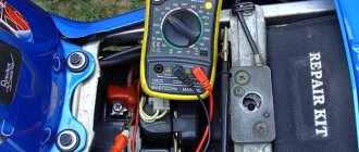
Correct use of the tool
AC/DC Holdpeak HP-605A attachment pliers. for high currents
In general, the clamps were originally intended to be paired with the HP890CN multimeter - there is a corresponding position on the selector. But in principle they can work with any other tester or even an oscilloscope, because they produce a voltage directly proportional to the measured current - 1mV corresponds to 1A.
The pliers have dimensions of 175x80mm (without the side button that opens the “mouth”), weight about 300g, wire length 70cm.
The kit includes a piece of paper that I can't even call it an instruction. It says something like this: connect the clamp to the tester, turn it on, select the “clamp” mode on the tester, switch the clamp and tester to the appropriate AC/DC mode, press the REL button on the tester - and measure. No numbers, errors, limits - nothing. However, the instructions from HP890cn promise 2.5%/3% +5 for DC and AC, respectively.
On the front panel there is a power button, an LED indicating the on state and an AC/DC button. Looking ahead, I will say that the difference between AC and DC is in the capacitor connected in series, and the trimmers for AC and DC are different.
Powered by the crown, current consumption 4.4mA
Output signal - 1mV=1A
The inner world is simple and unpretentious - LDO 7550 at 5V, converter from +5V to -5V 7660 and operational amplifier TL062
on the back of the board there are three trimming resistors, buttons and a power LED.
diagram (if I haven't messed something up):
The names of microcircuits, buttons, connectors are arbitrary (for example, instead of 7550 I drew 78L05, the connectors were taken based on the number of contacts, etc.). I didn’t unsolder or ring the capacitors; for the resistors, the inscriptions on them and their translation into the real value are indicated (because for 0603 with 1% accuracy the designation is not a digit-digit-multiplier, but a whole table)
If I understand correctly (and with a high probability I’m wrong), VR1 sets the initial offset, that is, it adjusts the zero, and VR2 and VR3 calibrate by constant and variable, respectively.
The AC mode differs in addition to a different output circuit and potentiometer - a capacitor connected in series. Why is this needed? As for me, there is a great secret. Apparently, to cut off the constant displacement that is inevitable in the clamps on the hall sensors. How this will differ from switching the tester to AC mode - I don’t even know. As for me, it would be better if they introduced a trimmer for this purpose and quickly set it to 0 at a constant value.
Now measurements. As I already wrote in the title, clamps are designed for high currents. Therefore, at low currents there will be no accuracy, but nevertheless we will try to check.
constant:
change:
As we can see, if during the regular period the accuracy is still pretty good, then during the break it’s not at all good. however, I don’t care much about measuring alternating currents, and I don’t care about such high currents at all, so for me personally this is not a problem, but if I understand correctly, you can, if desired, adjust (?) using VR2 and VR3, which is what I did for direct current, although I didn’t take a photo. But it turned out no more than +-0.1A with the reference tester, at the above currents, which I consider to be quite a good result. Well, they are not designed for such currents. They need tens and hundreds of amperes - there they will show more accurately and “open up to the fullest.”
Usage example
Let's give an example of how to use current clamps when measuring load on a 220 V network, for example in an apartment. In this case, the switch must be set to position AC 200. Next, you need to grasp the insulated conductor with a current clamp and take readings. After this, the resulting current value must be multiplied by the network voltage of 220 V. For example, if the device shows 5 A, then the power consumption in the network will be P = U * I = 5 * 220 = 1100 W or 1.1 kW. The obtained value can be used to check the operation of electricity meters.
Finally, we suggest watching a video that clearly shows how to use the DT-266 and Fluke 302+ current clamps, which are quite popular today:
DT-266 Fluke 302+
That's all the instructions on how to use current clamps yourself. As you can see, there is nothing complicated. The main thing is to follow safety measures and take measurements carefully. We hope that our tips and visual video instructions clearly explained the procedure to you!
It will be interesting to read:
- How to use a multimeter - instructions for dummies
- How to check if your electricity meter is working correctly
- List of electrician's tools
Correct use of the DT-266 Fluke 302+ tool Material taken from the site: https://samelectrik.ru/
Special Features
The following special features can make using current clamps easier:
- On-screen icons allow you to understand at a glance what is being measured (volts, ohms, etc.).
- The data hold function allows you to record the readings on the display.
- A single switch makes it easy to select measurement functions.
- Overload protection prevents damage to the device and circuit, and also protects the user.
- Automatic detection of the measuring range ensures that the correct range is always selected. Manual setting allows you to fix the range for repeated measurements.
- The presence of a low battery indicator will ensure timely replacement of batteries.
Error
This is the maximum permissible error that can occur under certain operating conditions. In other words, it is a measure of how closely the measured value matches the actual value.
Instrument error is usually expressed as a percentage of the reading. For example, if it is 1%, then for 100 amperes the actual current value is in the range from 99 to 101 A.
In addition to the uncertainty, the specifications may indicate how much the reading in the rightmost digit of the quantity being measured changes. For example, if the error is specified as ± (2% + 2), then for 100.0 A the actual current is in the range of 97.8 - 102.2 A.
Tags: ampere, sconce, upper, view, choice, , clamp, measurement, like, capacitor, contactor, circuit, crown, , magnet, power, multimeter, load, voltage, oscilloscope, potential, principle, wire, start, , work , size, resistor, row, light, LED, network, resistance, circuit, ten, type, current, transformer, installation, hall, shield, effect
Technology of use
How to use current clamps can be found in the attached operating instructions for the device. Documentation of this nature must be attached to the measuring device. The procedure for handling the tool is quite simple. The pliers cover the conductor and record the output data of the device. However, there are some tricks and nuances here.
Useful nuances of taking measurements
Sometimes when measuring small currents it becomes difficult to take readings with a clamp-on multimeter. A small current cannot be detected due to insufficient sensitivity of the measuring device.
To achieve this, a simple way to obtain data under these conditions was invented. They do it like this:
- The wire in the middle of the length is bent in half in a small area;
- The resulting loop is threaded into the opening of the magnetic cores 2 or 3 times.
- As a result, several wires appear in the device window.
- The multimeter switch is set to the minimum range of the measured value.
- The resulting number on the instrument display is divided by the number of conductors located in the instrument window. This will be the actual amount of current in one wire.
Additional Information. It should be taken into account that this method of taking readings allows for a large measurement error. The only advantage is that you can quickly measure the current strength of the cable under test.