The most basic generator function – battery charge battery and power supply for engine electrical equipment.
Therefore, let’s take a closer look at
the generator circuit , how to connect it correctly, and also give some tips on how to check it yourself.
A generator is a mechanism that converts mechanical energy into electrical energy. The generator has a shaft on which a pulley is mounted, through which it receives rotation from the engine crankshaft.
- Accumulator battery
- Generator output "+"
- Ignition switch
- Generator health indicator lamp
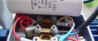
- Noise suppression capacitor
- Positive power rectifier diodes
- Negative power rectifier diodes
- Generator "mass"
- Field winding diodes
- Windings of three stator phases
- Field winding power supply, reference voltage for voltage regulator
- Field winding (rotor)
- Voltage regulator
A car generator is used to power electrical consumers, such as the ignition system, on-board computer, car lighting, diagnostic system, and it is also possible to charge a car battery. The power of a passenger car generator is approximately 1 kW. Car generators are quite reliable in operation because they ensure uninterrupted operation of many devices in the car, and therefore the requirements for them are appropriate.
Using a changeover switch
In fact, this is also a connection to a distribution machine, only without the need to disconnect the input wiring.
A three-position switch is mounted in front of the machine to avoid unscrewing the wiring. The task of this switch is to switch the network power from one branch to another (from an external network or generator). To perform this function, you need to select a switch with 4 input terminals (2 “phases” and 2 “zeros”), since the generator has its own “zero”, and a three-terminal switch will not work in this case. An alternative to a 3-position switch would be to install a pair of two-way machines next to each other, but rotated 180 degrees to each other. The keys of both devices are secured with pins through holes specially provided for this purpose. In operation, when switching the keys, for example, down, such a combination of machines will block the power supply to the network from the external line and open the way for the electric current generated by the autonomous generator. The opposite action with the keys will lead to the passage of current from the power line and blocking the flow of energy from the generator.
For convenience, such a switch should be installed in close proximity to the generating device, since it is launched in a certain sequence:
- Direct start of the generator engine.
- Warming up the device.
- And only then connect the load.
Naturally, it is more convenient to perform these actions and control the process in one place.
To prevent the generator from running in vain, that is, when voltage is already supplied to the backup line, it is necessary to mount a terminal for the lamp in front of the switch. Turning it on will signal the need to turn off the autonomous source and switch to supplying electricity from the main power line.
Charging diagram for VAZ with injection engines
This scheme is identical to the schemes on other VAZ models. It differs from the previous ones in the method of exciting and monitoring the serviceability of the generator. It can be carried out using a special control lamp and a voltmeter on the instrument panel. Also, through the charge lamp, the generator is initially excited at the moment it starts working. During operation, the generator operates “anonymously,” that is, excitation comes directly from pin 30. When the ignition is turned on, power through fuse No. 10 goes to the charging lamp in the instrument panel. Then it goes through the mounting block to pin 61. Three additional diodes provide power to the voltage regulator, which in turn transmits it to the excitation winding of the generator. In this case, the indicator lamp will light up. It is at that moment when the generator operates on the plates of the rectifier bridge that the voltage will be much higher than that of the battery. In this case, the control lamp will not light up, because the voltage on its side on the additional diodes will be lower than on the side of the stator winding and the diodes will close. If the control lamp lights up while the generator is running, this may mean that additional diodes are broken.
How to properly connect a generator to the home network
Connecting a power plant to your home network is possible in several ways. A popular option is to connect the network reserve through a changeover switch or packet switch.
How to connect a generator to the network at home
For the case of automatic connection of a power plant with auto-start, an ATS system (automatic transfer of reserve) is used. It is also possible to connect various household appliances through an extension cord with several sockets. In this case, the extension cable cross-section is calculated based on the total load current.
Installation of a changeover switch
The easiest way to connect an electric generator to your home is to install a changeover switch or packet switch. The batch switch is installed on a DIN rail in the electrical panel of the house. The switch is placed near the electrical panel.
The external electrical network is connected to the upper contacts of the switch, and the lower contacts are used to connect the cable from the power plant. The middle pins connect the home network input. After installing and connecting the changeover switch, put on the protective housing.
Connecting the generator through a switch and automatic transfer switch (ATS)
It is recommended to connect the switch after the electric meter and before the water dispenser. When the mains voltage disappears, the generator is started. After the engine has warmed up, the changeover switch is moved to the lower position (to the contacts going to the generator). After the network appears, the switch is moved to the upper position and the power plant is turned off.
Connecting the power plant via ATS
For automatic control of the power grid and automatic transition to a backup generator in the event of a network failure, there is an ATS device with automatic start-up of power plants. The AVR system monitors the electrical network and, when it disappears, disconnects the magnetic starter from the network and turns on the autostart of the generator.
When the generator reaches its rated speed, another magnetic starter is turned on, which connects the home network to the power plant. When the network is restored, the ATS disconnects the home network from the generator and connects another starter to the external network.
Connecting a 3-phase generator to a three-phase network at home
This transition from the backup generator does not occur immediately after the network appears, but with some time delay until the external network becomes stable. For the case of three-phase networks, it is recommended to install a single-phase generator, and connect all necessary household appliances and equipment to it via a separate backup electrical wiring with a changeover switch.
In a private home, AVR does not always pay off, since it always has to be controlled. With the same success, you can use a changeover switch and start the power plant manually. It is recommended to use a switch in case of rare outages of the external network.
Power plant grounding
For electrical safety purposes, in cases of voltage breakdown on the generator housing, a grounding connection is required. For power plants, you can make a simple ground loop. A piece of steel pipe, a pin or a metal rod with a diameter of 20 mm and 1.5 meters in length, is driven completely into the ground.
Generator grounding
At the end of the grounding conductor it is necessary to weld a bolt for the grounding conductor. As a conductor, a copper stranded flexible wire of 4-6 mm², with external insulation, is used.
The installation location of power plants must be selected taking into account fire safety, noise, precipitation and room temperature.
Electrical wiring in the house
Before connecting the generator to the house, I analyzed the state of the house network. After the meter I had two 25A machines. I decided to immediately change them, since the wiring in the house is old.
I have many articles on choosing a circuit breaker, here is the main one. Here, in relation to the apartment.
Counter and circuit breakers.
Third, IEK is not connected. The PVS cable that goes up goes to the summer kitchen. It was decided to install the generator near the summer kitchen, under a canopy, so power from the generator will come through this cable.
Through an automatic (distribution) switch
The ideal option is if the panel has an outlet. This method should not be confused with the one described above. On the electrical goods market, some ready-made panels are initially equipped with such outputs (it is recommended to choose them for private households). Sometimes, when assembling the panel yourself, they install an incoming AV, a meter, an RCD and one or two sockets for insurance, so it is convenient to carry out repairs. Then the generator can be connected there without any problems.
You need to be reliably aware that this is not an ordinary power outlet.
The rules must be followed:
- the socket must pass at least 16 A or more under the power of the backup device;
- AV at the input must be disabled.
If the described elements are not in the shield, then remove the input wires from the switchboard and connect the device directly to it. If RCDs and RCBOs are further installed, the polarity must be observed. Let us remind you: if you connect to the “firefighter” AB in front of the metering device, the circuit will work, but the meter will count its own electricity already produced. The introductory AB is sealed by energy sales, so more often than not the possibility of this option is completely absent. It is necessary to choose exactly the distribution (group, common) AB or RCBO after the metering device.
Algorithm of actions:
- Turn off the input machine. After connecting the backup source, it can be activated again, and this will be necessary before installing the control lamp.
- Unscrew the clamps on the switchgear terminals and remove the wiring.
- In place of the indicated cores, observing the polarity, especially if further than the RCD, RCBO, connect the cores from the generator cable.
- You can mount a light bulb on the folded wires, which will indicate the resumption of the main power supply; after installing it, the introductory circuit breaker is turned on.
Where should the station be located?
The room should be dry , with good ventilation. In addition, a very unpleasant hum emanates from the generator during operation. Taking these nuances into account, it is better to install and connect the electrical installation in a garage, outbuilding or under a canopy.
The electric generator is installed on a foundation that does not have a rigid connection with the building. You can place the device on special shock absorbers or on a rubber cushion. This helps reduce the sound of the generator.
Installing special noise-protective enclosures also helps reduce the hum.
Switch Connection
The simplest way to connect a generator is using a switch. The switch operates in three positions. In the initial position, the object is connected to a centralized power grid, without the participation of a gas generator.
When the switch moves to the next position, the object is completely de-energized. The next time you turn the switch, the power to the home network switches to a backup source - a gas generator.
Keep in mind that if the total power of all consumers is 6 kilowatts, then the switch must support at least 30 Amps.
A simple way to organize auto switching
In order not to manually switch the switch every time there is no electricity supply from the main power supply line of the household, you can make a fairly simple circuit that allows you to automatically switch from an external network to an autonomous one after starting the gas generator.
To install an auto-switching circuit, you will need two starting devices (contactors) that have a cross connection. During their operation, power as well as normally closed contacts will be involved. In addition to this set, if you need to provide the generator with a certain period of time for warming up, it is worth purchasing a time relay.
When voltage is created in the home electrical network from an external line, the main input contactor coil will keep the power contacts in the closed state, and the normally closed ones, on the contrary, in the open state.
When the voltage in the power transmission line disappears, the power contacts will open, and the normally closed ones will, accordingly, go into the closed state, which will allow, after a period of time specified by the temporary relay, after the generator is started, to supply voltage to the coil of the backup input contactor. As a result, the power contacts on the backup starter will close, and electric current from the gas generator will flow into the home network.
You may be interested in: Selecting a circuit breaker
When the centralized supply of voltage to the network of a private house is restored, the coil of the main starter will work, which will lead to the closure of the power contacts of this contactor and the automatic shutdown of power from the gas generator. The owner of the house just has to remember to stop the engine of the device for autonomous generation of electricity.
Choice
The buyer must determine from the very beginning which technical parameters are the most important for him. It is worth taking a closer look at these indicators:
- Weight.
- Dimensions.
- Power.
- Fuel consumption.
- Noise level.
- Duration of work.
Automation and price are parameters that are also being looked at
This is important for those who are interested in how to connect a generator to the home network, the diagram of which is posted on specialized websites
Generator operation
By parameters
Many people first look for an answer to the question of how many phases a generator should have for maximum convenient operation. To do this, you need to understand what electrical appliances will be connected. Three-phase options allow connection to both single- and three-phase devices. Single-phase ones are combined with only one type of consumer. But this does not mean that models with more phases will be better under all circumstances.
At each phase, the maximum load should be no more than 30%. This means that in reality the owners will not be able to use more than a third of the rated power that the outlet initially has. For example, the rated power of a three-phase generator is 6 kW. This means that no more than 2 kW can be removed from a regular 220 V outlet. The load still needs to be distributed over several phases when connecting a single-phase generator to a three-phase network at home.
Note! For power, they also check the parameters of the devices that are planned to be connected
It is important to have a reserve of at least 20-30%. Otherwise, you may encounter problems such as overload and work stoppage. Too much fuel will also be consumed
Too much fuel will also be consumed
Otherwise, you may encounter problems such as overload and work stoppage. Too much fuel will also be consumed.
Type
Synchronous and asynchronous types of devices are available. The choice involves a careful study of the characteristics of each of the existing models.
Asynchronous
Their main problem is their inability to handle so-called peak loads. Although these devices can also be used to maintain normal voltage readings. They are suitable for joint use with equipment sensitive to voltage surges:
- Electronic devices.
- Computer Engineering.
- Medical devices supporting gasoline generators.
Residual magnetization of the rotor is the main source of energy for such devices. Therefore, the service life of asynchronous generators is longer than that of their closest analogues. They do not require the use of cooling systems; the unit housing is completely closed. Thanks to this, protection from dust and moisture is fully guaranteed.
Interesting! The asynchronous generator is immune to short circuits. Therefore, this energy source is the optimal solution for welding machines. But such devices can be very sensitive to overloads. Therefore, it is prohibited to connect them to devices with initially high inrush currents.
Synchronous
The quality of the current in this case is lower when compared with the previous option. Suitable for providing emergency power in various circumstances:
- Offices.
- Refrigeration units.
- Electrical equipment in dachas and country houses.
- Construction projects.
Such devices also have some positive qualities:
- Resistance to short-term overloads.
- Ability to normally withstand peak loads, including mechanical loads.
But protection from moisture, dust and dirt is worse than that of asynchronous structures. After all, in order to cool, such generators need to pass a certain amount of air through themselves. A synchronous generator will be needed if devices operating with reactive loads are used. Then the power will be less.
Changeover switches
Phasing
It has already been mentioned above. It is worth buying three-phase generators only if there is a consumer with the appropriate characteristics in the house. If all the devices are single-phase, then the generator is selected of this type. This even applies to situations where there is a three-phase network connected to the house.
Network connection
About contactors
Thus, the use of conventional relays is out of the question for us; only specialized contactors are suitable.
For higher powers there is also an option with motorized drives, but this is expensive and redundant for typical home use. To make a mechanical interlock, you need to select contactors that can work in pairs. Typically, mutual interlocking is achieved by installing identical contactors next to each other and installing an additional option - a mechanical interlock. It is sold separately from contactors and costs pennies.
Mutual electrical interlocking is possible if the contactor has additional signal contacts that operate to open. Sometimes they are immediately built into the contactor, sometimes they can be purchased and installed as an option.
Leading contactor manufacturers have such equipment in their lines. So finding and buying a kit is not difficult. True, prices for branded contactors are an order of magnitude higher than ours/Chinese ones. Since the number of switching cycles is not expected to be large, the choice of Chinese contactors is quite justified. The only disadvantage is that the contactor coils hum quite loudly during operation.
More about the switching power. The contactor contacts must be able to handle the maximum amount of power you are allowed to draw in your home. For me it is 10 kW, so I chose contactors for a permissible current through one contact of approximately 50 amperes. It is worth noting that for some reason the switched power for a typical three-phase contactor is indicated in the passport as the total for all three phases, so you need to carefully look at what the permissible current is through exactly one contact.
How to connect the generator?
The electric generator can be connected in two ways:
- Through a switch (connection to the panel);
- Using automatic or semi-automatic reserve input.
The generator is connected to the panel using a changeover or reversing switch:
- Before installing it, a cable is laid, depending on the power of the generator.
- Then the switch itself is installed in the panel in a special box, protecting it from rust and corrosion.
- After that, all that remains is to connect the switch (the main network cable is located on top, the private circuit of the house is in the center, and grounding is below), and start the generator.
Connecting a generator with a semi-automatic automatic transfer switch involves installing two semiconductors in protective boxes that are connected to each other. When the lights go out, you need to start the backup power source, then there will be an automatic transition from the main network to the generator.
Automatic reserve input means turning on the generator automatically, without any intervention.
Input rework
The voltage from the street after the meter enters the house through a two-pole circuit breaker No. 1, and then through circuit breakers No. 2 and No. 3.
And the voltage from the generator is through machine No. 2.
The most important thing is that when the generator is running, machine No. 1 must be turned off!
What happens if you turn on the generator without turning off the input circuit breaker? In the best case, the circuit breakers will work, in the worst case, the generator will burn out, and/or the electrician of the repair team will receive a voltage shock from Victor’s generator!
It turns out that the generator is now connected to a special outlet on the wall of the summer kitchen. When the generator operates, the voltage goes to the summer kitchen, and then to machine 2, and then to machine 3 and into the house.
New circuit breakers installed
In the middle there is a 220V indicator, which is connected BEFORE the input machine, immediately after the meter. Thus, even during the day, I can immediately find out that there is light on the street, turn off the generator, and connect power from the street with automatic 1.
Connecting machines
The result is this nice design:
Electrical panel with meter and machines
What types of generators are there?
Many people think that generators and uninterruptible power supplies are mutually interchangeable and identical. But that's not true. UPS are devices that provide current only for a while. Their work is just enough to save important information on the computer, for example. The generator can produce electricity many times longer.
There is another device that many also confuse with generators. These are voltage stabilizers. They equalize the voltage if surges occur in the network. Stabilizers protect equipment from sudden changes in network voltage, thereby extending the service life of electrical appliances.
Before answering the question of how to connect a generator to the home network, you need to understand which generators can be connected to the home network.
There are three main types of generators based on engine type:
- gasoline;
- diesel;
- gas.
A gasoline generator is used only for a short time; its operation is not suitable for long-term loads. If the main power source is, then gasoline units should be purchased only to maintain the operation of the devices for a short time (up to 12 hours), if there are frequent network outages.
The diesel generator is the most powerful unit. This is, in fact, a diesel station that can continuously generate electricity, or be used as a backup generator for lighting the house.
Gas generators consume the least amount of fuel, which is why they are considered the most economical generators. They can operate either from a gas cylinder or from a gas main.
Also, both gas and gasoline can be used as fuel in one generator - with the ability to switch. They are called dual-fuel.
There are two more types of generators - inverter and welding. Both gas and gasoline can be used as fuel.
Inverter generators have a distinctive feature - performance adjustment. For example, during a power outage, all appliances in the house are connected to the generator. If you turn off any device, automatic performance adjustment will work, and the generator itself will reduce the load.
Welding generators are designed to power welding machines, mainly manual ones.
The number of phases and the cooling system also depend on the type of generator.
Based on the number of phases, generators are divided into single-phase (output voltage 220 V) and three-phase (380 V). The first are used in residential buildings where there is only one power and ground line. A three-phase generator provides power via three power lines, with one grounding line.
Generators use air or liquid cooling. The first is used on generators or power plants whose power does not exceed 6 kW. Liquid cooling is installed on more powerful generators, the number of engine hours of which is about thirty thousand. It is better to buy such generators on official websites or in specialized stores to prevent interference with the device by unscrupulous sellers.
How to connect a three-phase generator?
In the case of using a switch, a winding is required for each phase separately, that is, a jumper from one phase to another.
Generator switching sequence
The main secret of safety is in following these simple rules for turning on the generator. I hung them in front of the counter so I wouldn't forget. Besides, I may not be at home, my wife will turn on)
If there is no light from the street
1. Turn off ENTER (automatic 1)
2. Go to the generator, connect it to a special outlet.
3. Check that the load switch on the generator is turned off. Also, make sure that all heavy loads in the house are turned off.
4. Start the generator, let it warm up and go into operation for at least 30 seconds.
5. Turn on the machine on the generator.
6. Turn on the required load one by one.
If the light was given
1. The appearance of voltage on the street line is indicated by a red indicator under the meter.
2. Turn off the powerful load
3. Turn off the generator, turn off the load switch at its output.
4. Pull the generator plug out of the socket.
5. Turn on the introductory machine No. 1.
All this is done automatically by the ATS system; a person only needs to pull the starter on the generator. And if the generator has automatic start, you don’t need to do anything at all!
Automatic generator start via AVR unit
The purpose of such devices is to partially or completely eliminate human participation in the operation of the generator. There are two main types of such devices. The first completely copies the auto-switching system, which operates on two starters, but with the addition of an electronic unit for starting and stopping the generator. A low-current cable is connected to it from the main power supply line, through which the unit receives information about the presence or absence of voltage in the network. Depending on this, it sends a command to the engine to start or stop, and switching between input from the main line or from the generator is performed by the starters themselves. In general, this is the same system as the proposed scheme for self-assembly, but here you don’t have to invent anything - just install a ready-made unit.
The disadvantage of such a block is the same - its purpose is only to start and stop the engine without additional protection.
The diagram itself looks like this:
1. Introductory machine. 2. Electricity meter. 3. Automatic generator start block. 4. Generator. 5. Time relay. 6. RCD. 7. Main input contactor. 8. Backup input contactor.
A more advanced option is a complex system controlled by microprocessor electronics. In general, it works in the same way as a homemade autostart system, but its main advantage is the presence of numerous sensors that monitor all aspects of the generator's operation. If any equipment malfunction occurs, the ATS unit will be able to react adequately - not torment the generator with autostart attempts, but if there is a GSM module, send a message to the owner about the malfunction.
The ATS unit itself is mounted instead of a distribution panel - this does not require much knowledge - you just need to connect wires from the main line, power and control cables from the generator and output to the house to it.
1. Introductory machine. 2. Electricity meter. 3. AVR. 4.Generator. 5. Control cable. 6. Consumer machines. 7. Zero bus. 8. Grounding bus.
Such a unit is a complex set of equipment and its cost in some cases can be equal to the price of a generator. Therefore, its purchase is justified only in case of frequent power outages and for sufficiently powerful generators.
“Emergency” connection methods and their disadvantages
Typically, “fire” methods are used in cases where for some reason it is impossible to use the generator directly - you need to connect it to your home network urgently, and there is no time to install a separate connection circuit.
What distinguishes a specialist from an ordinary person, among other things, is knowledge of the reasons for prohibitions - this is what allows one to bypass them at the right moments: to do something not according to the rules, but to get the desired result. Just don’t forget the platitudes - electricity does not forgive mistakes, which means you need to calculate your actions several steps ahead in order to eliminate all possible mishaps.
Connection via socket
The most common “fire” way to connect a generator to a house is to simply plug it into an outlet, for which you buy or make your own “carrying” with plugs at the ends.
This method is strongly discouraged, but the simplicity of its use has won over many owners of small and medium power generators time and time again.
The principle of using such a connection becomes clear if you look at a standard home wiring diagram. Indeed, if you connect a current source to one of the sockets, voltage will appear in all parts of the circuit.
1. Introductory machine. 2. Electricity meter. 3. Generator. 4. Distribution machine. 5. Sockets.
There are not so many disadvantages of this method, but you need to remember about them so as not to damage the generator.
1. Wire overload.
You can ignore this point if you use a generator with a power of up to 3 kW. Socket lines are standardly connected with a wire with a cross-section of 2.5 mm², and the sockets themselves are designed for a maximum current of 16 Amps. According to the table of the ratio of cable cross-section to the current strength that they can pass, even aluminum wires (which are already prohibited for installation) of this cross-section can easily withstand power up to 3.5 kW.
| Cable core cross-section, mm2 | Cable core diameter, mm | Copper core | Aluminum core | ||||
| Current, A | Power, kW at network voltage 220 V | Power, kW at network voltage 380 V | Current, A | Power, kW at network voltage 220 V | Power, kW at network voltage 380 V | ||
| 1 | 1,12 | 14 | 3,0 | 5,3 | — | — | — |
| 1,5 | 1,38 | 15 | 3,3 | 5,7 | — | — | — |
| 2,0 | 1,59 | 19 | 4,1 | 7,2 | 14 | 3,0 | 5,3 |
| 2,5 | 1,78 | 21 | 4,6 | 7,9 | 16 | 3,5 | 6,0 |
| 4,0 | 2,26 | 27 | 5,9 | 10,0 | 21 | 4,6 | 7,9 |
| 6,0 | 2,76 | 34 | 7,7 | 12,0 | 26 | 5,7 | 9,8 |
| 10,0 | 3,57 | 50 | 11,0 | 19,0 | 38 | 8,3 | 14,0 |
| 16,0 | 4,51 | 80 | 17,0 | 30,0 | 55 | 12,0 | 20,0 |
| 25,0 | 5,64 | 100 | 22,0 | 38,0 | 65 | 14,0 | 24,0 |
| 35,0 | 6,68 | 135 | 29,0 | 51,0 | 75 | 16,0 | 28,0 |
Using the formula for finding power P=I*U, you can determine the maximum current supplied by the generator. If its power is 3 kW and the voltage is 220 Volts, then I = 3000 / 220 ≈ 13.65 Amperes, i.e. the safety margin of even a standard outlet should be more than enough (of course, if these are not outdated, still Soviet models, designed for a maximum at 6.3 or 10 Amps).
Another thing is generators of higher power - for them all calculations must be carried out separately. True, they are all usually permanently connected and the urgent need to “throw” them through an outlet can only arise in the event of a wiring fault. This is where you need to know for sure what is being violated and whether it can be done.
2. Human factor.
Before turning on the backup generator, it is imperative to turn off the input circuit breakers. If this is not done, then in the best case, part of the power will simply go to the neighbors, and the generator will stall from overload. It will be worse if, at the moment of trying to start the generator, the supply of electricity to the main line is resumed - this is guaranteed to burn the electric motor winding with counter currents.
If trouble is possible in principle, then sooner or later it will happen. Even if you attach a large sign to the generator body reminding you of the need to turn off the input circuit breaker, there is always a chance of making a mistake in a hurry.
3. Use of protective devices.
If the wiring in the house is made in accordance with the recommendations of the PUE, then individual outlet lines, in addition to standard circuit breakers, will be protected using residual current devices (RCDs). In addition to the fact that they must be connected in compliance with polarity, many of them are designed to connect the current source to the upper terminals and the load to the lower ones.
1. Introductory machine. 2. Electricity meter. 3. Distribution machine. 4. RCD. 5. Consumer machines.
Accordingly, when you plug the generator into a socket, you will need to monitor where the phase and zero are, and it is also quite likely that only the adjacent sockets will work, and when you try to even turn on the light, the RCD will trip. There is no point in correcting the circuit for the sake of a few hours of generator operation, so the only way out here is to turn it on directly through the switchboard.
In addition to all the existing disadvantages, the emergency scheme for connecting the generator to the home network through an outlet does not imply the ability to track when electricity appears on the main line in order to switch back in time. For this you need at least a separate signal light, but since the input machine is turned off, it is not possible to use it.
Connecting the generator to the switchboard
This is the most correct way to quickly connect a generator, but with some nuances that must be taken into account.
The easiest way to make such a connection is if there is an outlet next to the switchgear - it is often installed in case of repair work or simply for insurance. True, you need to imagine exactly how this outlet is connected - the best option is shown in the diagram.
1. Introductory machine. 2. Electricity meter. 3. Generator. 4. Socket. 5. Distribution machine.
In this case, everything depends only on the capacity of the outlet itself (16 Amperes) and you must remember to turn off the input circuit breaker.
If such an outlet was not provided when installing the panel, then you will have to unplug the wiring from the input of the distribution machine and connect the generator directly to it
If there are RCDs further along the circuit, then the polarity must be observed.
1. Introductory machine. 2. Electricity meter. 3. Generator. 4. Distribution machine.
The main thing here is not to confuse which machine to connect to. If suddenly there is access to an input circuit breaker in front of the meter, and the generator is connected to it, then in general the circuit will not change... It will simply include an electricity metering device, which does not care what counts - the current from the main line or generated by the generator.
1. Introductory machine. 2. Electricity meter. 3. Generator. 4. Distribution machine.
However, the likelihood of such an error/connection is small, since the meter and the input machine are sealed by inspectors from the energy supervision department.
Since the wires from the main line fold out, you can connect a control light to them - when it lights up, it means the generator can be turned off. The input machine must be left on.
1. Introductory machine. 2. Electricity meter. 3. Generator. 4. Distribution machine.
Connecting the generator via a changeover switch
In essence, this is the same connection of the generator to the switchgear, but already equipped with a stationary three-position switch so that you do not have to unscrew the wires from the terminals of the circuit breaker.
By three-position is meant a switch to which current can be supplied from two different branches, but the load is connected to only one of them. The third position is neutral to prevent contact of incoming wires. Since the generator has its own zero, the switch must be selected accordingly - installing a single-wire one, through which only the phase is switched, is not possible here.
If you don’t have a three-position switch at hand, then you can temporarily make a two-position changeover device from two two-pole circuit breakers. It is advisable to take them from the same manufacturer and denomination so that the sizes match. The machines must be installed side by side, but one of them must be turned upside down, and the keys must be fastened together - for this, the manufacturers provide holes for pins.
A person who understands electrics can build such a device from four single-pole circuit breakers - without turning them over and switching each one separately. But if someone other than him will start the generator, then it’s better to take care of “foolproofing” right away.
The switch itself is installed near the generator. This is the most convenient, since it is started in a certain order: first the generator itself starts, and when it warms up, the load is connected to it.
To prevent the generator from working in vain, after turning on the electricity on the main line, you need to make a tap for the signal lamp and place it in a conspicuous place. To prevent it from shining all the time, it must be connected via a switch. If you are afraid of forgetting to turn it on, then you can add an element of automation by connecting the lamp through any normally open contact of the starter. The entire diagram for connecting the generator through a changeover switch and with a signal lamp looks like this:
1. Introductory machine. 2. Electricity meter. 3. Generator. 4. Distribution machine. 5. RCD.
As long as there is voltage on the main line, the entire circuit operates as usual - the current passes through the switch and then goes to the switchgear. When the electricity goes out, you need to manually start the generator and transfer the load from the house to it. When the generator starts, current flows through the coil of the KM starter and its contacts close - the signal lamp is turned on to the network and when electricity appears on the main line, the lamp lights up.
The simplest auto-switching scheme
So that you don’t have to flip the switch every time you need to start the generator, you can assemble a simple automatic switching circuit for the current source. This is not an autostart system - its purpose is only to switch the input between the main line and the generator, and starting and stopping the engine will still have to be done manually.
The minimum parts required for this are two starters (contactors) - KM1 and KM2 with cross connection. They will involve power contacts (KMk) and normally closed (KMnz). To give the generator time to warm up, it is additionally advisable to use a time relay.
The figure shows a diagram of how to connect a generator to the network at home - it works according to the following principle:
1. Introductory machine. 2. Electricity meter. 3. Distribution machine. 4. Generator. 5. Time relay. 6. Main input contactor. 7. Backup input contactor.
As long as there is electricity on the main line, the KM1 coil keeps the KMk1 power contacts closed and the normally closed KM1nz1 and KM1nz2 open. When the electricity is turned off, the power contacts KMk1 open, and KM1nz1 and KM1nz2 close - now when the generator starts, after the time for which the relay is designed, voltage will appear on the KM2 coil, the power contacts KMk2 will close and current will be supplied to the house from the generator.
When electricity appears on the main line, the KM1 coil is triggered - the contacts KM1nz1 and KM1nz2 open, de-energizing the KM2 coil. The power contacts KMk2 open, and KMk1 close and power to the house again comes from the main line. All you have to do is remember to turn off the generator itself.
Grounding
The very principle of operation of the generator involves the periodic occurrence of static electricity on its body, therefore all permanently installed devices necessarily require a separate grounding circuit.
The ideal option is to create a full-fledged grounding loop, but in general you can get by with the simplest method, for which you will need a metal rod 1.5-2 meters long, a steel bolt or clamp connection and a soft copper wire. A bolt is welded to the iron rod, and the pin itself is driven the entire length into the ground. The copper wire is screwed with one side to the bolt (or clamped with a clamp), and the other to the generator housing - the grounding is ready.
These are all the main ways to connect a gas generator to the network at home and possible nuances. The presented diagrams will help determine whether it is worth installing autostart systems or whether it will be easier to do with manual switching. Of course, when installing each individual generator, ATS unit or homemade autostart system, additional questions may arise, but they will have to be resolved in each case separately, depending on the device model and the home electrical circuit diagram.
Basic connection tasks
When installing electrical installations, the following indicators must be taken into account :
- need for automation;
- location in terms of efficiency and safety;
- stock selection;
- frequency of network outages;
- power consumption taking into account losses.
It is important to create a suitable connection diagram for a gasoline generator.
Automation of the process is expensive and requires qualified maintenance. Manual connection for a private home is the most gentle mode. Such switches are produced in two types: a changeover type switch (old model) or a reversible switch (three-way). You can find out more about them below. They also use partial automation, because semi-automatic machines are inexpensive. Regardless of the chosen method, you need to monitor the operation of the system.
UPD: Connecting the boiler to the generator.
Often a generator is purchased to be used in winter to power the heating system boiler. There are some peculiarities here.
For imported phase-dependent boilers, it is important that the power system has a solidly grounded neutral, i.e. neutral and ground are connected together, and when connecting, the polarity is observed (phase-zero)
In the case of a portable generator, which is discussed in the article, there is neither zero nor phase. They must be made artificially - one output of the generator will be a phase (L2), and the second (N2) will be placed on the ground, i.e. ground.
In addition, as is known, boilers are very sensitive to the voltage form. And at the output of a conventional generator, the sine wave is “dirty”; if necessary, I will take an oscillogram. First of all, this happens because... The alternator that generates electricity is brushed, and because of the brushes sparking, failures, and similar unpleasant things occur.
It is because of this that Off-line and Smart UPS are not suitable for boilers. There at the output there is a quasi-sine with a bunch of harmonics, the oscillograms can be viewed here. And for boilers, Online UPS (double conversion uninterruptible power supplies) is used. For such a UPS, the shape, magnitude and frequency of the input voltage are not particularly important, because it cooks a constant voltage from all this mess, from which it then electronically receives a pure sine wave. And if the boiler is powered through such a UPS, then you can use a regular generator for its backup power.
For boilers and other sensitive equipment, it is recommended to use inverter generators - this is a generator plus an online UPS. The inverter generator includes a regular generator, which is controlled by a controller, and an inverter, which produces pure sine wave - what boilers need.
Checking generator operation
You can check the functionality of the generator in several ways using certain methods, for example: you can check the output voltage of the generator, the voltage drop on the wire that connects the current output of the generator to the battery, or check the regulated voltage.
To check, you will need a multimeter, a car battery and a lamp with soldered wires, wires for connecting between the generator and the battery, and you can also take a drill with a suitable head, since you may have to twist the rotor by the nut on the pulley.
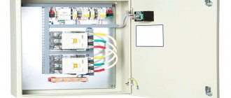
Distribution board diagram with a “network-generator” switch
Details Published: 04 June 2015
In dacha areas, garden plots, the private sector and similar places, frequent power outages are common. Here they can turn off the lights for an hour, for the whole day or for a longer time. This creates quite a few problems, since people can no longer imagine life without electricity. He has things working at home: a refrigerator, a TV, room lighting, a pump for watering the garden, and the like.
Gasoline power plants are very popular in such places. Turn off the lights, start the gas generator and continue to enjoy life. The power plant must be connected to the distribution board through a special outlet. Below I look at the diagram of a distribution board with a “mains-generator” switch, which allows you to switch to power supply from a gas generator when the external network is lost and back.
Here I am considering manual switching, which is carried out using a reversing switch. All diagrams show an ABB OT40F3C switch. This is a high-quality and reliable reversible switch. It has three positions:
- the handle is turned to the left - the contacts on its left side are closed, and on the right side they are open;
- the handle is in a vertical position - all contacts are open (both right and left);
- the handle is turned to the right - the contacts on its right side are closed, and on the left side they are open.
If what is written is not entirely clear, then look at the latest diagram and you will immediately understand how it works.
It is worth noting that if you take such a reversing switch for a higher current, then the switch handle is not included in the kit. It must be purchased separately.
Below is a simple single-phase switchboard diagram with a mains-generator switch. This is plenty for a small dacha or garden house. If you have a large house, then you need to revise the ratings of the input machine and increase the number of group lines. Everything is individual here.
It is very convenient to use a network indicator in such panels. For example, the signal lamp LS-47. Why is she needed here? Let's say the lights are turned off and you start the power plant. Everything is working.
Next, how to determine whether there is voltage in the network or not? You won’t run to the switchboard every half hour and use an indicator to check whether the light is on or not. This is not convenient and is forgotten over time. So you can miss this moment and “sit” on the gas generator until the evening. And gasoline is expensive these days.
In such a situation, the mains voltage indicator will immediately show you when the light comes on
It will just light up and you will immediately notice it. It is clearly visible from afar even through the transparent cover of the shield. As soon as the warning light came on, they immediately turned off the power plant and switched the switch to mains mode
As soon as the warning light came on, they immediately turned off the power plant and switched the switch to mains mode.
Below is the same diagram of the distribution board, but with an LS-47 signal lamp.
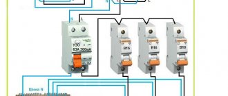
If you want to protect yourself and your dacha from current leaks, then you need to install an RCD. Below is a diagram with one common protective device. If you want more, then go ahead and fight. Here you can fantasize endlessly.
For a better understanding of the operation of such a circuit, I schematically showed the state of the contacts of the reversing switch with red lines and the direction of the current with red arrows.
Below is the work from an external network.
And here the work from a gas generator is already presented.
And these are already two diagrams of the operation of this switchboard in one. It looks like a cartoon. Like?
At the request of site visitors, I am posting below a 3-phase electrical panel diagram with a “network-generator” switch
Also don't forget to smile:
A drunk man goes home and hits his head on every lamppost. Then an acquaintance meets him and asks: “Why are you hitting the pillars like that, why are they bothering you?” Can't get around? “That’s not the point at all, it’s just how I determine the way home.” - Didn't understand. - What’s incomprehensible here? Here are 3 more pillars along this street, then 7 more along another - and I’m home.
About AVR schemes
There are several different schemes for implementing ATS. Next I will write about the safest, from my point of view, single-phase ATS circuit. I do not advise economically making an ATS on one contactor or with switching only one phase wire. Only together with neutral.
In the diagram shown, power from the network and from the generator is supplied through inputs 1 and 2. They are protected by paired circuit breakers. The switching and indication circuits are powered through additional circuit breakers. It can be seen that the relay coils are electrically interlocked. For the sake of simplicity, a microcontroller not shown in the diagram, which closes the circuits at the switching point TK1 or TK2, is responsible for turning on one or another input.
The fundamental point is the presence in the ATS of 2 interlocking circuits - mutual mechanical interlocking of the contactor switching inputs and mutual electrical interlocking of the contactors. In order to save money, home-made people sometimes neglect these blockings in their designs, but in vain. A circuit without interlocks can work for some time, but at some point the contacts will burn, the return springs will weaken and a short circuit will occur between the inputs. Firstly, it threatens a big bang if both lines are energized, but this is not the biggest problem. It is much more important that your generator, unexpectedly for the electricians repairing the wiring, can release voltage into the general network - in an unfavorable combination of circumstances, the electricians repairing the line may die. For you this is already a criminal article.
Connection diagram of a single-phase generator to a three-phase network
Let's consider the key points of connecting a single-phase generator to a three-phase network. Recently, this topic was created on the forum, and I decided to give a more detailed answer, as well as discuss this issue on the blog, since many readers do not visit the forum.
Connecting a single-phase generator is relevant for private houses and cottages that want to have an independent power source.
Many luxury houses (cottages) have three-phase input due to high power consumption. Here the question may arise: what kind of generator is needed? A three-phase generator of the required power suggests itself.
Generator for a private home
Is a three-phase generator really necessary?
I will not give a definitive answer to this answer, however, I assume that a single-phase generator will be cheaper than a three-phase one.
I have already told you why three-phase input is bad. The main problem is that it is very difficult to achieve uniform phase distribution. Perhaps the generator does not tolerate operating modes very well when there is constant phase imbalance.
But how can we convert our three-phase shield into a single-phase one?
Everything is very simple. Scheme for automatically connecting a single-phase generator to a three-phase network:
Connection diagram of a single-phase DG to a three-phase network
For this we need only 2 contactors, not counting the auxiliary elements.
In normal mode, consumers are connected to a three-phase network through the KM1 contactor. If the main power is turned off, the generator starts. Starting can be done using the additional contact of the KM1 contactor. Contactor KM1 is turned off, and contactor KM2 is turned on and combines phase 3 into one.
If you do not need automatic starting of the generator, then instead of this ATS you can use, for example, a cam switch for the appropriate power. The connection diagram is similar to KM2. Here we must use either two manual switches or 1 switch, and turn off the supply network with an input circuit breaker.
Which solution is preferable? The choice is yours.
I also advise you to review my old articles:
I recommend reading:
“Scheme for connecting a single-phase generator to a three-phase network”
“At the same time, do not forget that the power of a single-phase generator will be at least 2 times greater than a three-phase one.”
They didn’t write about the zero cross section.
I don't understand the question about power.
The cross section of the zero is not less than the cross section of the phase wire. For example, VVG-3×16.
Why will the power of a single-phase generator be at least 2 times greater than a three-phase one?
About zero. Which cable to lay from the automatic transfer switch to the distribution board with a three-phase input with a power of 15 kW. Emergency diesel is acceptable at 15 kW.
Single-phase diesel respectively.
You calculate the current, select the machine, and then select the cable cross-section. At 15kVA - VVG-3×16
But then how will there be power from the network in three-phase mode?
The supply cable from the three-phase network will be your own, for example SIP4-4×16 or SIP4-4×25.
from the support to the ATS and from the diesel engine to the ATS everything is already clear. What kind of cable is placed from the AVR to the distribution board? And why is the power of a single-phase generator 2+ times greater than the power of a three-phase generator?
After AVR, you will have group lines. There should be no intermediate shields.
When you transfer all electric motors to one phase, the total Kc should decrease, therefore the power of the single-phase generator will be Pantryk:
There should be no intermediate shields.
If the ATS is built into a panel with group devices, then yes, there will be devices right away. And if the AVR is a separate design. It includes two cables (one from the diesel engine and one from the support) and one goes to the panel with group devices. So I’m talking about the zero of such a cable. Or for example, I have a two-story mansion and the allocated power is 30 kW, and I set the diesel to the same 15 kW. At the same time, I have a switchboard for the second floor. It is three phase. It comes with a 5x4 cable. And now we apply common-mode voltage to all phases. What happens to zero? In the particular case with one input distribution board, nothing bad will happen because The tire section is quite sufficient
But in the general case of using a single-phase generator in a three-phase network, it is worth paying attention to the zero cross-section in three-phase cables and groups
I did not consider all the nuances in detail, and did not become attached to a specific object. We always need to look at what currents we will have and, depending on them, select machines and cable sections.
If you have a project, we can discuss it in more detail on the forum.
Difference between single and three phase connection
All connections, whether in a single-phase or a three-phase network, are made completely identical, with the exception of the number of power wires. The only important nuance concerns the so-called control phase - if you connect the starter to the network, then its main contacts connect and disconnect the power wires from the network, and the power for the electromagnetic coil must also be taken from somewhere.
In a single-phase network there are no problems - there is only one phase and such a question simply does not exist, but in a three-phase network everything is somewhat more complicated - there are L1, L2 and L3. Without going into technical details, there is only one answer - for control circuits you can use any of the phases, but only one. That is, if the KM1 coil is powered from phase L3, then the control of the remaining starters, the “Start” and “Stop” buttons must also be “hung” only on it.
This is not difficult to do - just note what color the wire is on the desired phase, and if the cable has single-color conductors, then stick or draw markers on them.
V. Comfort
Generators make a lot of noise (especially diesel ones). It is very unpleasant if a power outage occurs at night and the automation starts the station. During work, you can smell exhaust gases in the area.
The inverters operate completely silently. On-line UPSs make noise with cooling fans - it is advisable to install them in a separate room. The batteries are completely sealed and no gases are released during charging or discharging.
Conclusion No. 5. Uninterruptible operation is more comfortable and environmentally friendly.
Device and main parameters of generation
Three-phase generator design
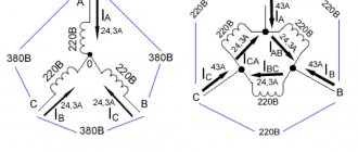
A three-phase generator is a device that operates on the principle of converting the mechanical energy of a rotating shaft into electricity. In addition to the moving part associated with the drive, it consists of three coils made up of many windings and placed on the stator core. In brushless generators, when the rotor rotates, an EMF is induced in the coils, whose parameters correspond to the standards of 3-phase mains power. This means the following:
- the resulting voltages have a sinusoidal shape;
- the amplitude of each of the 3 phases is 220 Volts;
- the voltage between them is 380 Volts;
- frequency of generated oscillations – 50 Hz.
A design feature of such units is a phase shift of 120 degrees.
An alternating voltage is supplied from the stator coils to the serviced line, providing it with the necessary power of 380 Volts.
Possible mistakes
In addition to connecting a powerful power station to an outlet, the home owner is capable of making the following mistakes:
- Install the unit in a windproof basement, which can lead to overheating and concentration of toxic exhaust gases.
- Place the generator outdoors – the device can be damaged by snow or rain.
- Do not make grounding.
- Incorrect input cable cross-section.
- Perform switching of a switch or reversing device under load.
All these errors can cause a short circuit in the generator circuit with unpredictable consequences.