Winding connection options
An asynchronous three-phase electric motor has three windings - for each phase separately - going into the stator slots. However, for the generation of electromotive force and, as a result, rotation of the rotor, they must be connected to each other. It is important to know the connection option for a specific motor. Since this will help you choose the right scheme for connecting it to the 220V network.
Each of the three windings corresponds to its own phase and has both a beginning and an end. In this case, the inputs and outputs are designated by the corresponding letters and numbers:
Range of engines produced during the Soviet Union:
- The first phase is C1-C4.
- Second phase C2-C5.
- Third phase C3-C6.
Designations of modern engines:
- First phase U1-U2.
- Second phase V1-V2.
- Third phase W1-W2.
Connecting the winding of a three-phase motor Source autogear.ru
There are two main circuits for connecting the windings in the type of motor under consideration:
- Star.
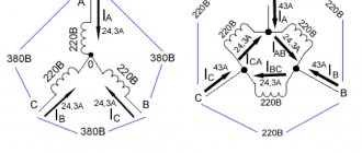
All winding outputs are connected to one point, and the inputs, respectively, to the phases. The schematic representation of this method looks like a star. With this method, a 220V phase is applied to each individual core, and a linear 380V is applied to two consecutive cores.
The main advantage of this scheme is the application of linear current to two wires simultaneously, which significantly reduces inrush currents and allows the rotor to perform a soft start. The downside is lower power due to weak currents in the winding.
- Triangle.
The input of the previous winding is connected to the output of the next one - and so on in a circle. As a result, the diagram resembles a triangle. At a linear voltage of 380V, the currents in the winding will reach a significantly higher value than in the above option. This will make it possible for the motor to exert a significantly greater amount of force. The disadvantage of the circuit is that stronger inrush currents can lead to network overload.
Triangle diagram Source ytimg.com
Good to know! To obtain the advantages of the first and avoid the disadvantages of the second circuit, the connection of the 380 V electric motor and its subsequent acceleration is carried out on the “star”, and then it is automatically switched to the “delta”.
general information
Connecting three-phase motors involves a relatively complex operation that requires an understanding of the processes occurring in the electrical installation. For this purpose it is necessary to consider both the constituent elements and their purpose.
Structurally, three-phase electric motors consist of:
- Stator with magnetic core;
- Rotor with shaft;
- Winding.
Depending on the type of engine, there are models with a squirrel cage or wound rotor. In some, the rotor rotates only due to the electromagnetic field induced from the stator windings, in others, the rotation of the shaft receives force from the rotor field when current flows in its windings. To turn on three-phase motors, you need to understand how the phases of the windings are connected to each other.
Definition of connection diagram
Before choosing one or another scheme for connecting a motor to 220 V, it is necessary to determine what the connection diagram for its winding is and at what rating it can generally be operated. To do this you need:
- Find and study the technical table on the engine. characteristics .
The information field contains all the important information - designation of the type of connection ∆ - triangle or star - Y , power, number of revolutions, voltage (220 or 380, or 220/380) and the possibility of connecting according to a specific circuit.
- Open the terminal box and verify in practice that the assembled circuit is correct.
The beginning and end of each winding is signed in accordance with the above alphanumeric nomenclature. The user remains to study the connection diagram using jumpers: according to what scheme the connection is made - star or triangle.
Note! If the nameplate (table with information) indicates the Y and only 380V, then when it is connected in a triangle, the winding will burn out. Only professional electricians can upgrade such a 220V motor. Therefore, there is no reason to modify it, especially since today there are many copies that can operate alternatively - both 220 and 380 volts.
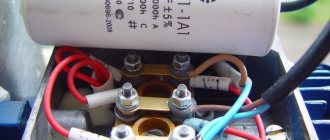
Opening the terminal box Source pikabu.ru
See also: Catalog of companies that specialize in electrical work
Connecting a 380 V asynchronous motor to a three-phase network in reverse
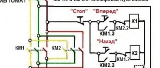
The connection diagram of an asynchronous machine in the forward direction has a certain sequence of supplying phases A, B, C to the motor contacts. It can be modified, for example, by adding a switch that would swap any two phases. In this way you can obtain a motor reverse circuit. In practical circuits, such phases are considered to be B and A.
Optional equipment:
- Magnetic type starters (KM1 and KM2).
- A station with three buttons, where two contacts have a normally open position (in the initial state the contact does not conduct current, when the button is pressed, the circuit closes), one is normally closed.
The scheme works as follows:
- By turning on the automatic fuses AB1 (power line), AB2 (control circuit), the current flows to the three-button switch and the terminals of the magnetic contactors, which are open in the initial state.
- By pressing the “Forward” button, the current passes to the coil of the electromagnet of contactor 1, which attracts the armature with power contacts. At the same time, the control circuit of contactor 2 breaks, and it is now impossible to turn it on with the “Reverse” button.
- The motor shaft begins to rotate in the main direction.
- By pressing the “Stop” button, the current in the control winding circuit is interrupted, the electromagnet releases the armature, the power contacts open, the blocking contact of the “Reverse” button closes, and it can now be pressed.
- When the “Reverse” button is pressed, similar processes occur only in the contactor 2 circuit. The motor shaft will rotate in the opposite direction from the main direction.
Connection methods for 220V
To connect a three-phase asynchronous electric motor to a 220-volt network, there are several proven methods:
- With capacitor.
- Without capacitor.
- With reverse.
- Combined star-delta circuit.
Let's look at them in more detail.
Important! When connecting a 380-volt electric motor to a 220-volt network, you need to be prepared to reduce its power to 70% of the factory value. However, in everyday conditions this is quite acceptable and will not affect the performance in any way.
Connecting a 380 V motor to 220 V Source ytimg.com
With capacitor
The most popular and affordable way to initiate 380 volt motors from a 220 V network is a circuit using a capacitor. Its role is to create a phase shift in the windings relative to each other in order to form a rotating magnetic field. If there are three phases, this phenomenon occurs by itself - only one will not force the rotor to rotate. Therefore, the optimal method for connecting an electric motor with 4 wires on one phase is to use a starting winding, in addition to the main winding, in 220V electric motors.
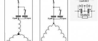
For the 380 V modification, two connection options with a capacitor are possible:
- With working capacitor Cp .
- And parallel connected working Cp and starting capacitor Sp .
In the second case, the engine starts more smoothly and safely. Sp module turns on for a short period of time and turns off as the rotor reaches the required speed. The choice of starting option is largely determined by the degree of rotor load during starting. So, if the start occurs without force, only Cp , and if under load, without free rotation, the presence of Cn .
Connecting a motor with capacitors Source blogspot.com
Capacitors for starting an electric motor - how to select and calculate
The function of stabilizers is that they act as capacitive energy fillers for stabilizer filter rectifiers. They can also transmit signals between amplifiers.
To start and operate for a long period of time, capacitors are also used in the AC system for asynchronous motors.
The operating time of such a system can be varied using the capacitance of the selected capacitor.
The first and only main parameter of the above-mentioned tool is capacity. It depends on the area of the active connection, which is isolated by a dielectric layer. This layer is practically invisible to the human eye; a small number of atomic layers form the width of the film.
An electrolyte is used if it is necessary to restore the oxide film layer. For proper operation of the device, the system must be connected to a network with alternating current of 220 V and have a clearly defined polarity.
That is, a capacitor is created in order to accumulate, store and transmit a certain amount of energy. So why are they needed if you can connect the power source directly to the engine. It's not that simple.
If you connect the motor directly to a power source, then at best it will not work, at worst it will burn out.
In order for a three-phase motor to work in a single-phase circuit, you need a device that can shift the phase by 90° on the working (third) terminal.
Useful tips
Some useful tips on how to connect a 3-wire motor to avoid problems during operation:
- Before starting work, it is recommended to test the engine at idle, if it is functioning properly, then under load.
- If the case becomes very hot, even without load, it is necessary to reduce the capacity of the working capacitor.
- If after starting the motor just hums, but does not rotate the shaft, then you can set it to start manually - by turning the shaft. Next, you can increase the capacity of the starting capacitor.
- When stopping the engine under operating load, the capacity of the working capacitor should be increased.
Helpful information! It is possible to correctly calculate the capacitance of the capacitor only taking into account the power rating of the motor. If there is underload, overheating will occur and the capacity will need to be reduced.
Selecting a capacitor for a three-phase motor
Capacitors intended for a three-phase motor must have a fairly high capacity - from tens to hundreds of microfarads. Electrolytic capacitors are not suitable for these purposes because they require a unipolar connection. That is, specifically for these devices it will be necessary to create a rectifier with diodes and resistances.
Gradually, the electrolyte in such capacitors dries out, which leads to loss of capacity. In addition, during operation, these elements sometimes explode. If you still decide to use electrolytic devices, you must take these features into account.
Classic examples are the elements presented in the figure. The working capacitor is shown on the left, and the starting capacitor is shown on the right.
The selection of a capacitor for a three-phase motor is carried out experimentally. The capacity of the working device is selected at the rate of 7 μF per 100 W of power. Therefore, 600 W will correspond to 42 µF. The starting capacitor is at least 2 times the operating capacitance. Thus 2 x 45 = 90 uF would be the most appropriate figure.
The choice is made gradually, based on the operation of the engine, since its real power directly depends on the capacity of the capacitors used. In addition, this can be done using a special table. If there is insufficient capacity, the engine will lose its power, and if there is excess capacity, overheating will occur from excessive current. If the capacitor is selected correctly, the engine will operate normally, without jerking or extraneous noise. We select the device more accurately through calculations performed using special formulas.
Briefly about the main thing
You can connect a 380 to 220 volt electric motor in 4 main ways:
- With capacitor.
- Without capacitor.
- With reverse.
- Star-delta design.
Before starting connection work, it is necessary to determine and verify how the winding is connected in the terminal box, and also find out the necessary characteristics from the technical table. You can perform electrical work if you have experience, but it is better to entrust it to professionals with the appropriate permit.
Ratings 0
What is reverse
Simply put, reverse is a change in the direction of movement of any mechanism in the opposite direction from the selected main one. The reverse circuit can be obtained in several ways:
- Mechanical
- Electric.
In the first case, by switching the gear connections connecting the drive shaft to the driven shaft, the latter is rotated in the opposite direction. All gearboxes work on this principle.
The electrical method involves a direct effect on the engine itself, where electromagnetic forces take part in changing the movement of the rotor. This method benefits from the fact that it does not require the use of complex mechanical transformations.
In order to obtain electric motor reverse, it is necessary to assemble a special electrical circuit, which is called a motor reverse circuit. It will differ for different types of electrical machines and supply voltage.
How to distinguish a reversing starter from a direct one
A reversing starter is a more complex device. In fact, it consists of two conventional direct starters, the latter combined in one housing. The internal circuitry of the reversing device is characterized by the fact that it is impossible to run two modes at the same time - direct and reverse. This process is controlled by a blocking circuit, which can be electrical or mechanical.
