- January 22, 2021
- Tools and equipment
- Yulia Tolok
In everyday life, a situation often arises when it is necessary to connect an electric motor, but there is no necessary power source. Then the use of a different type of voltage is required. This usually happens if the engine needs to be connected to third-party equipment (lathe, homemade device). Capacitors are used for this purpose. They come in several types, so you need to have at least a basic understanding of which capacitors to use to start an electric motor in each specific case.
What is a capacitor
A capacitor is a radio element consisting of two plates with a dielectric between them. Its main purpose is to create a buffer between the plates to store charge. There are three types of capacitors:
- Polar. Used in DC systems. These are electrolytic capacitors, which, due to their special structure, have polarity. They are not very suitable for connecting to AC sources due to the destruction of the dielectric layer with the release of a large amount of heat, which sometimes even leads to explosions.
- Non-polar. Designed for use in both types of circuits.
- Electrolytic. This category includes only non-polar capacitors of this type. They have an oxide film as a lining. Optimal option for low-frequency motors due to the high possible capacity.
Each type of engine has its own characteristics for selecting a capacitor. This determines what capacity the capacitor is needed to start the engine, what rated voltage and what type.
Using Electrolytic Capacitors
Capacitors with a dielectric made of paper are characterized by a low specific capacitance and significant dimensions. For an engine of even not the highest power, they will take up a lot of space. Theoretically, they can be replaced by electrolytic ones, which have several times higher specific capacity.
Types of electrolytic capacitor devices
To do this, the electrical circuit will have to be supplemented with several elements: diodes and resistors. This option is not bad for an occasionally running engine. If long-term loads are planned, then it is better to abandon saving space and weight - if the diode accidentally fails, it will begin to pass alternating current to the drive, which will lead to its breakdown and explosion.
The solution can be polypropylene capacitors with metal coating of the SVV series, designed for use as starting capacitors.
Connecting a single-phase motor
To connect an asynchronous motor to a single-phase circuit, a voltage of 220 V is usually used. But to start it, it is necessary to create a rotary displacement torque of the rotor. For this purpose, a starting winding is used, which is additional and functions only when starting. The phase shift is set on it using a capacitor.
The capacity is selected according to the following principle. The total capacitance (operating and starting) per 100 W of power is approximately 1 µF. If you need to select capacitors to start a 1.5 kW electric motor, then it is quite easy to calculate: 1.5 x 1000: 100 x 1 = 15 µF. Thus, to connect a single-phase asynchronous motor with a power of 1.5 kW, it is necessary to use a working and starting capacitor with a total capacity of 15 μF.
Such engines have several operating modes:
- Connected additional winding to the starting capacitor. The capacitance is selected based on 70 microfarads per kilowatt of power.
- An additional winding is used throughout the entire period of operation together with a working capacitor, the capacity is about 30 µF.
- Connecting two types of capacitors at the same time.
The operating principle of a single-phase 220 V electric motor.
A magnetic field is generated in the stator of a 220 V single-phase electric motor. This is the impulse that drives the rotor. To imagine how an electric motor functions, it is worth simulating the following situation.
For example, there is no voltage in the starting winding. The formation of a magnetic field can be started by connecting the main winding to the network. Its work is based on pulsation, while the space remains at rest. The magnetic field is divided into two parts, each of which rotates in directions opposite to each other, at the same frequency. When the rotor is given an initial rotation, the engine will increase it over time. In this case, the frequency of the element and the magnetic field itself differs. The difference in indicators is defined as slip.
A driving force arises from magnetic fluxes. This is the law of electromagnetic induction. The driving force generates two types of current. One of them is reverse, the second is direct. The rotor speed is directly proportional to the slip rate. According to Ampere's law, a magnetic field, when interacting with a reverse current, creates rotation.
Capacity calculation methods
To calculate which capacitors are best used to start an electric motor, the following formula is used:
- C = k x If: Uc,
Where:
- k is the coefficient, it differs depending on the type of connection, 4800 is a triangle and 2800 is a star;
- If – starter current (indicated on the engine);
- Uc is the network voltage, in this case 220 volts.
The output is a capacitance measured in µF (one millionth of a Farad). It can be calculated in another way, using power as the main parameter.
Every 100 W of motor power corresponds to 7 µF. It should not be forgotten that the starter winding must receive a current no higher than the rated current.
Specifics of circuits with capacitors
When selecting the types of switching on of electric machines using starting and working two-terminal circuits for a 220 volt network, the following are distinguished:
- inclusion in the “triangle”;
- star connection.
For your information. What are the differences between starting and working two-terminal networks? “Starting” are elements that are used only for starting, and “working” are those that are constantly used in operation.
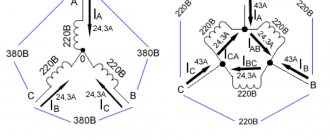
Connection diagrams for a 380 V line
There is no need to use capacitive elements when connecting a 3-phase motor to a 380 volt network.
Connecting the motor to a three-phase network
Schemes for connecting to a single-phase network
When installing a single-phase motor in a single-phase line, it is started using an additional winding. Such a motor has three outputs:
- from the working coil;
- from additional;
- common output for both windings.
When there is no marking, the coils are “ringed” by a tester to determine the correct connection.
Circuit for starting a single-phase motor
Assembly type "Triangle"
To connect an asynchronous three-phase machine to a single-phase line, it is possible to use a delta connection. The starting capacitance is turned on according to the diagram.
Turning on the motor via a delta connection
Assembly type "Star"
The principle of assembling the starting circuit of a 3-phase motor, the windings of which are connected by a star, is similar. When it is possible to independently make such a connection of the windings, it is carried out on the terminal block.
Star connection
Connecting two capacitors for a three-phase motor
To start the engine under load, a starting capacitor must be added. It operates in the first few seconds during startup and stops working when the rotor reaches operating mode (speed). To select a capacitor for the engine in this case, you should know that its design voltage exceeds that of the working capacitor by 1.5 times, the capacitance by 2.5-3 times.
More than one capacitor can be connected. If you connect them in parallel, the capacity will increase, which is convenient for calculations.
After turning on the engine the first time, it is necessary to monitor its operation. It shouldn't get too hot. If it is not clear which capacitors to use for the electric motor in this case, then the correct answer is with a lower capacitance. The operating voltage is at least 450 V. In order for the engine to operate efficiently, it is necessary not only to correctly determine all the parameters of the capacitor used, but also to take into account the conditions of its load or operation.
How does the load size affect the choice of capacitors?
If the part is selected in accordance with the calculations given here, then it will fit well under a uniform load. An example of such a situation is the operation of a fan.
If the load changes, then in this case you can use the following trick. For example, you can consider a circular saw, which is used to cut boards and logs. In the first case, it is obvious that the load is less, and in the second - more.
For example, if calculations were made based on the rated current and a capacitance equal to 10 microfarads was obtained, then you need to use such a working capacitor when sawing boards. It will most likely not be enough to work with logs. In this case, when performing work, two such parts are connected in parallel.
If this is not done, the engine will lose power. As a result, it will begin to overheat and to work on it you will need to take breaks to allow the motor to cool down.
To start the engine you need to connect a starting capacitor Source chipmaker.ru
Differences between starting and running capacitors
The starting capacitor is needed to start the motor, so it works for a short time at the beginning, after which it turns off, while the motor continues to work (a phase shift is created in the winding). Consequently, the time when the starting capacitor is activated is about 3 seconds, since over a longer period it can become very hot and lead to a short circuit in the motor circuit, which will certainly be followed by failure of the circuit elements.
This type of capacitor is used on electric motors whose connection diagram provides for this starting mode. For other engines, it can also be used if, at the moment of starting, an increased load is created on the shaft, which does not allow the rotor to rotate freely.
The working capacitor sets the phase shift for constant operation of the engine, therefore it is calculated taking into account longer operation. During a cycle phase change, a voltage appears on the capacitor that exceeds the supply voltage. This occurs due to the fact that, together with the winding, an oscillatory circuit is created. The latter is also important to consider.
Reversing the direction of movement of the engine
If, after connecting, the motor works, but the shaft does not rotate in the direction you want, you can change this direction. This is done by changing the windings of the auxiliary winding. This operation can be performed by a two-position switch, the central contact of which is connected to the output from the capacitor, and to the two outer terminals from “phase” and “zero”.
Failure of capacitors in the air conditioning compressor circuit is not so rare. Why do you need a capacitor at all and why is it there?
Low-power household air conditioners are mainly powered by a single-phase 220 V network. The most common motors used in air conditioners of this power are asynchronous with an auxiliary winding, they are called two-phase electric motors or capacitor motors .
In such motors, two windings are wound so that their magnetic poles are located at an angle of 90 degrees. These windings differ from each other in the number of turns and rated currents, and, accordingly, in internal resistance. But at the same time they are designed so that during operation they have the same power.
In the circuit of one of these windings, its manufacturers designate it as a starting winding, they include a working capacitor, which is constantly in the circuit. This capacitor is also called a phase-shifting capacitor, since it shifts the phase and creates a circular rotating magnetic field. The working or main winding is connected directly to the network.
Comparison of both types of capacitors
The working and starting capacitors have the following differences:
- Use in various connection circuits: working and starting.
- The working capacitor generates an electromagnetic field for the main cycle of engine operation; the starting capacitor sets the phase shift between two windings - working and additional - at the beginning of operation.
- The first is connected in series with the auxiliary winding, the second in parallel with the main winding.
- The working capacitor is active all the time while the engine is on, the starting capacitor is only at the start until it reaches constant mode.
- As already noted, the principle of selecting a container is also different. Every 100 W corresponds to 7 µF for the running capacitor and 13-17 µF for the starting capacitor. The coefficient of increase in the maximum permissible voltage is also different compared to the nominal one: for operating voltage - 1.15, starting voltage - 2-2.5.
These rules help to at least roughly understand what kind of capacitor is needed to start an electric motor.
Design and operating principle
The electric motor is connected through a capacitor because one winding on the stator of a 220 V AC electric motor creates a magnetic field that compensates for its impulses by changing polarity with a frequency of 50 Hz. In this case, the engine hums, the rotor remains in place. To create torque, additional connections are made to the starting windings, where the electrical phase shift will be 90° relative to the working winding.
Do not confuse geometric concepts of position angle with electrical phase shift. In the geometric dimension, the windings in the stator are placed opposite each other.
To achieve this technically, the design of the electric motor provides a large number of mechanical parts and electrical circuit components:
- stator with main and additional starting windings;
- squirrel cage rotor;
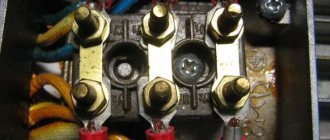
- boron with a group of contacts on the panel;
- capacitors;
- centrifugal switch and many other elements shown in the above picture.
Let's look at how to connect a single-phase motor. In order to shift the phases, a capacitor is connected in series to the starting winding; when a single-phase asynchronous electric motor is connected, a circular magnetic field induces currents in the rotor. The combination of field forces and currents creates a rotating impulse applied to the rotor, it begins to rotate.
Connection principles
From a safety point of view, it is recommended to follow these rules:
- Each time after turning off the engine, discharge the capacitor. The charge accumulated by it can lead to failure of the circuit. Some capacitors may have a built-in discharge resistor that is selected to fully discharge within 50 seconds of turning off the power.
- Live parts must be insulated so as not to accidentally touch them.
- The capacitor housing must be securely fastened so that it does not move during operation.
If you have doubts about your ability to select the correct capacitors to start the electric motor and connect the device yourself, it is recommended to seek help from a specialist.
Sometimes the question may arise as to what kind of capacitor is needed for a DC motor. The fact is that such engines do not need capacitive elements in the circuit. But capacitors can also be used there; they are placed on the brush mechanism to eliminate interference. They have a completely different operating principle.
Diagrams and recommendations for connecting an electric motor through a 220V capacitor
Most owners of private garages or workshops are faced with the question of how to connect a 380V electric motor to 220V through a capacitor or other methods.
Some types of equipment that may be privately owned, such as concrete mixers, grinders or woodworking machines, consume a lot of power. An asynchronous three-phase motor can provide it, but its main problem is that it is designed to connect to a 380V power network, which is absent or severely limited in most private households. We will consider options for getting out of the current 380/220 situation below.
Checking the performance of capacitors
To test capacitors, use a capacitance meter. It can be made either as a separate device or as part of a multimeter (tester). It’s easier to consider checking with a multimeter:
- First of all, it is necessary to de-energize the capacitor;
- further discharge it by short-circuiting the terminals;
- remove one of the terminals;
- switch the multimeter to the mode for measuring capacitance of capacitors;
- attach the probes to the terminals of the capacitor;
- read the capacity indicator from the screen.
The capacitance measurement mode on a multimeter can be displayed in different ways. Most have special Fcx sockets.
Before starting a capacitor test, it is recommended to manually (or automatically, depending on the model) switch the limit of the measured capacitance. Typically the maximum value is 100 µF, which is sufficient in most cases. There are other instruments that allow you to measure capacitance. They are made in the form of probes, tweezers or equipped with special connectors.
It is important to understand that the rating indicated on the capacitor body must correspond to the measured value. If this is not the case, then it should be replaced.
Replacement and selection of capacitor
If there is a capacitor similar to the burnt one, then it is enough to simply install it in place of the old one. Polarity does not play a role here.
Many people do not know which capacitors cannot be used to start an electric motor. Capacitors with polarity indications (electrolytic) must not be used. They are thermally destroyed when used in such circuits. As a rule, there are special ones for this purpose that are designed to work with alternating current and have no polarity, and also have special fastening and terminals for quick installation.
If the required rating is not available, then the easiest way is to connect several capacitors. This must be done in parallel, since with this type of connection the capacity will be total. At the same time, the maximum voltage for which they are designed to work does not increase. This connection diagram fully corresponds to the installation of a larger capacitor.
Simple ways to connect an electric motor
The simplest way to turn on motors is to connect to a three-phase network. The electrical windings of the motor are connected in two ways:
- star;
- triangle.
The connection order is indicated on the terminal cover on the reverse side.
Connection diagram
Attention! Connecting the windings in a delta quickly brings the motor to maximum power, but then the starting current increases sevenfold. A soft start, in the absence of a starting rheostat, is difficult.
The star connection of the windings allows the motor to operate steadily and for a long time with a smooth start. The machine can withstand short-term overloads and does not overheat. Its power is slightly lower than with an alternative connection.
The beginnings of the windings can be connected to one point during manufacturing. Only three of their ends are brought out to the terminal block. Therefore, the conclusions are simply connected to the network phases. The direction of rotation is selected by reversing the connection of the terminals to two adjacent phases.
A motor with only three wires out