Source: GOST 8593-81
Taper K is the ratio of the difference in diameters of two cross sections of a cone to the distance between them.
The slope “i” is the ratio of the difference in the sizes of two cross sections to the distance between them.
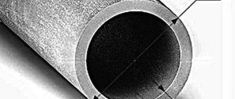
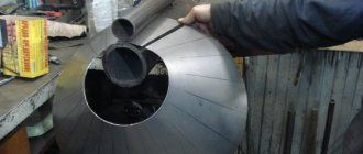
In mechanical engineering, along with cylindrical ones, parts with conical surfaces in the form of external cones or in the form of conical holes are widely used. For example, the center of a lathe has two outer cones, one of which serves to install and secure it in the conical hole of the spindle; a drill, countersink, reamer, etc. also have an outer cone for installation and fastening. The adapter sleeve for fastening drills with a conical shank has an outer cone and a conical hole
The concept of a cone and its elements
Elements of a cone. If you rotate the right triangle ABC around the leg AB (Fig. 202, a), then a body ABG is formed, called a full cone
.
Line AB is called the axis or altitude of the cone
, line AB is called
the generator of the cone
.
Point A is the vertex of the cone
.
When the leg BV rotates around the axis AB, a circle surface is formed, called the base of the cone
.
The angle VAG between the lateral sides AB and AG is called the cone angle
and is denoted by 2α.
Half of this angle formed by the lateral side AG and the axis AB is called the cone angle
and is denoted α. Angles are expressed in degrees, minutes and seconds.
If we cut off its upper part from a complete cone with a plane parallel to its base (Fig. 202, b), we obtain a body called a truncated cone
.
It has two bases, upper and lower. The distance OO1 along the axis between the bases is called the height of the truncated cone
. Since in mechanical engineering we mostly have to deal with parts of cones, i.e. truncated cones, they are usually simply called cones; From now on we will call all conical surfaces cones.
The connection between the elements of the cone. The drawing usually indicates three main dimensions of the cone: the larger diameter D, the smaller diameter d and the height of the cone l (Fig. 203).
Sometimes the drawing indicates only one of the cone diameters, for example, the larger D, the cone height l and the so-called taper. Taper is the ratio of the difference between the diameters of a cone and its length. Let us denote the taper by the letter K, then
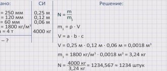
If the cone has dimensions: D = 80 mm, d = 70 mm and l = 100 mm, then according to formula (10):
This means that over a length of 10 mm the diameter of the cone decreases by 1 mm or for every millimeter of the length of the cone the difference between its diameters changes by
Sometimes on the drawing, instead of the angle of the cone, the slope of the cone
. The slope of the cone shows the extent to which the generatrix of the cone deviates from its axis. The slope of the cone is determined by the formula
where tan α is the slope of the cone; D is the diameter of the large base of the cone in mm; d is the diameter of the small base of the cone in mm; l is the height of the cone in mm.
Using formula (11), you can use trigonometric tables to determine the angle a of the cone.
Cone slope and taper are usually expressed as a simple fraction, for example: 1: 10; 1:50, or a decimal fraction, for example, 0.1; 0.05; 0.02, etc.
Methods for producing conical surfaces on a lathe
On a lathe, processing of conical surfaces is carried out in one of the following ways: a) turning the upper part of the support; b) transverse displacement of the tailstock body; c) using a cone ruler; d) using a wide cutter.
3. Machining conical surfaces by turning the upper part of the caliper
When making short external and internal conical surfaces with a large slope angle on a lathe, you need to rotate the upper part of the support relative to the axis of the machine at an angle α of the cone slope (see Fig. 204). With this method of operation, feeding can only be done by hand, rotating the handle of the lead screw of the upper part of the support, and only the most modern lathes have a mechanical feed of the upper part of the support.
To set the upper part of the caliper 1 to the required angle, you can use the divisions marked on the flange 2 of the rotating part of the caliper (Fig. 204). If the slope angle α of the cone is specified according to the drawing, then the upper part of the caliper is rotated together with its rotating part by the required number of divisions indicating degrees. The number of divisions is counted relative to the mark marked on the bottom of the caliper.
Read also: A mixture of aluminum and iron
If the angle α is not given in the drawing, but the larger and smaller diameters of the cone and the length of its conical part are indicated, then the value of the caliper rotation angle is determined by formula (11)
The method of turning conical surfaces by turning the upper part of the caliper has the following disadvantages: it usually allows the use of only manual feed, which affects labor productivity and the cleanliness of the machined surface; allows you to grind relatively short conical surfaces limited by the stroke length of the upper part of the caliper.
Machining of conical surfaces using the method of transverse displacement of the tailstock housing
To obtain a conical surface on a lathe, when rotating the workpiece, it is necessary to move the tip of the cutter not parallel, but at a certain angle to the axis of the centers. This angle must be equal to the slope angle α of the cone. The simplest way to obtain the angle between the axis of the centers and the direction of feed is to shift the line of centers by moving the back center in the transverse direction. By shifting the rear center towards the cutter (toward itself) as a result of grinding, a cone is obtained, the larger base of which is directed towards the headstock; when the rear center is shifted in the opposite direction, i.e., away from the cutter (away from you), the larger base of the cone will be on the side of the tailstock (Fig. 205).
The displacement of the tailstock body is determined by the formula
where S is the displacement of the tailstock body from the axis of the headstock spindle in mm; D is the diameter of the large base of the cone in mm; d is the diameter of the small base of the cone in mm; L is the length of the entire part or the distance between centers in mm; l is the length of the conical part of the part in mm.
The tailstock housing is shifted using divisions 1 (Fig. 206) marked on the end of the base plate, and mark 2 on the end of the tailstock housing.
If there are no divisions at the end of the plate, then move the tailstock body using a measuring ruler, as shown in Fig. 207.
The advantage of machining conical surfaces by displacing the tailstock body is that this method can be used to turn long cones and grind with mechanical feed.
Disadvantages of this method: inability to bore conical holes; loss of time for rearranging the tailstock; the ability to process only shallow cones; misalignment of the centers in the center holes, which leads to rapid and uneven wear of the centers and center holes and causes defects during the secondary installation of the part in the same center holes.
Uneven wear of the center holes can be avoided if a special ball center is used instead of the usual one (Fig. 208). Such centers are mainly used when processing precision cones.
5. Machining conical surfaces using a conical ruler
For machining conical surfaces with a slope angle of up to 10-12°, modern lathes usually have a special device called a cone ruler. The scheme for processing a cone using a cone ruler is shown in Fig. 209.
A plate 11 is attached to the machine bed, on which a conical ruler 9 is mounted. The ruler can be rotated around pin 8 at the required angle a to the axis of the workpiece. To secure the ruler in the required position, two bolts 4 and 10 are used. A slider 7 slides freely along the ruler, connecting to the lower transverse part 12 of the caliper using a rod 5 and a clamp 6. So that this part of the caliper can slide freely along the guides, it is disconnected from the carriage 3 by unscrewing the cross screw or disconnecting its nut from the caliper.
If you give the carriage a longitudinal feed, then the slider 7, captured by the rod 5, will begin to move along the ruler 9. Since the slider is attached to the transverse slide of the caliper, they, together with the cutter, will move parallel to the ruler 9. Thanks to this, the cutter will process a conical surface with an inclination angle , equal to the angle α of rotation of the conical ruler.
After each pass, the cutter is set to the cutting depth using the handle 1 of the upper part 2 of the caliper. This part of the caliper must be rotated 90° relative to the normal position, i.e., as shown in Fig. 209.
If the diameters of the bases of the cone D and d and its length l are given, then the angle of rotation of the ruler can be found using formula (11).
Having calculated the value of tan α, it is easy to determine the value of angle α using the table of tangents. The use of a cone ruler has a number of advantages: 1) setting up the ruler is convenient and quick; 2) when switching to processing cones, there is no need to disrupt the normal setup of the machine, i.e., there is no need to move the tailstock body; the centers of the machine remain in the normal position, i.e. on the same axis, due to which the center holes in the part and the centers of the machine do not work; 3) using a conical ruler, you can not only grind the outer conical surfaces, but also bore conical holes; 4) it is possible to work with a longitudinal self-propelled machine, which increases labor productivity and improves the quality of processing.
Read also: Tensile yield strength
The disadvantage of a tapered ruler is the need to disconnect the caliper slide from the cross feed screw. This drawback is eliminated in the design of some lathes, in which the screw is not rigidly connected to its handwheel and the gear wheels of the transverse self-propelled machine.
Machining conical surfaces with a wide cutter
Machining of conical surfaces (external and internal) with a short cone length can be done with a wide cutter with a plan angle corresponding to the slope angle α of the cone (Fig. 210). The cutter feed can be longitudinal or transverse.
However, the use of a wide cutter on conventional machines is only possible with a cone length not exceeding approximately 20 mm. Wider cutters can only be used on particularly rigid machines and parts if this does not cause vibration of the cutter and the workpiece.
7. Boring and reaming of tapered holes
Machining tapered holes is one of the most difficult turning jobs; it is much more difficult than processing external cones.
The machining of conical holes on lathes is in most cases carried out by boring with a cutter with turning the upper part of the support and, less often, using a tapered ruler. All calculations associated with turning the upper part of the caliper or the tapered ruler are performed in the same way as when turning the outer conical surfaces.
If the hole must be in solid material, then first a cylindrical hole is drilled, which is then bored into a cone with a cutter or machined with conical countersinks and reamers.
To speed up boring or reaming, you should first drill a hole with a drill, diameter d, which is 1-2 mm less than the diameter of the small base of the cone (Fig. 211, a). After this, the hole is drilled with one (Fig. 211, b) or two (Fig. 211, c) drills to obtain steps.
After finishing boring the cone, it is reamed using a conical reamer of the appropriate taper. For cones with a small taper, it is more profitable to process the conical holes immediately after drilling with a set of special reamers, as shown in Fig. 212.
Cutting modes when processing holes with conical reamers
Conical reamers work under more difficult conditions than cylindrical reamers: while cylindrical reamers remove a slight allowance with small cutting edges, conical reamers cut the entire length of their cutting edges located on the generatrix of the cone. Therefore, when working with conical reamers, feeds and cutting speeds are used less than when working with cylindrical reamers.
When processing holes with conical reamers, the feed is done manually by rotating the tailstock handwheel. It is necessary to ensure that the tailstock quill moves evenly.
Feed when reaming steel is 0.1-0.2 mm/rev, when reaming cast iron 0.2-0.4 mm/rev.
The cutting speed when reaming conical holes with high-speed steel reamers is 6-10 m/min.
Cooling should be used to facilitate the operation of conical reamers and to obtain a clean, smooth surface. When processing steel and cast iron, an emulsion or sulfofresol is used.
Measuring conical surfaces
The surfaces of the cones are checked with templates and gauges; measuring and simultaneously checking the angles of the cone is carried out using protractors. In Fig. 213 shows a method for checking a cone using a template.
The outer and inner corners of various parts can be measured with a universal goniometer (Fig. 214). It consists of a base 1, on which the main scale is marked on an arc 130. A ruler 5 is rigidly attached to the base 1. Sector 4 moves along the arc of the base, carrying a vernier 3. A square 2 can be attached to the sector 4 by means of a holder 7, in which, in turn, a removable ruler 5 is fixed. The square 2 and the removable ruler 5 have ability to move along the edge of sector 4.
Through various combinations in the installation of the measuring parts of the protractor, it is possible to measure angles from 0 to 320°. The reading value on the vernier is 2′. The reading obtained when measuring angles is made using the scale and vernier (Fig. 215) as follows: the zero stroke of the vernier indicates the number of degrees, and the vernier stroke, which coincides with the stroke of the base scale, indicates the number of minutes. In Fig. 215 the 11th stroke of the vernier coincides with the stroke of the base scale, which means 2'X 11 = 22'. Therefore, the angle in this case is 76°22′.
Read also: Abrasives for pastes
In Fig. 216 shows combinations of measuring parts of a universal protractor, allowing the measurement of various angles from 0 to 320°.
For more accurate testing of cones in mass production, special gauges are used. In Fig. 217, and shows a conical bushing gauge for checking outer cones, and in Fig. 217, b—conical plug gauge for checking conical holes.
On the gauges, ledges 1 and 2 are made at the ends or marks 3 are applied, which serve to determine the accuracy of the surfaces being checked.
On the. rice. 218 provides an example of checking a conical hole with a plug gauge.
To check the hole, a gauge (see Fig. 218), which has a ledge 1 at a certain distance from the end 2 and two marks 3, is inserted with light pressure into the hole and checked to see if the gauge is swinging in the hole. No wobble indicates that the cone angle is correct. Once you are sure that the angle of the cone is correct, proceed to check its size. To do this, observe to what point the gauge will enter the part being tested. If the end of the part's cone coincides with the left end of ledge 1 or with one of the marks 3 or is between the marks, then the dimensions of the cone are correct. But it may happen that the gauge enters the part so deeply that both marks 3 enter the hole or both ends of the ledge 1 come out of it. This indicates that the hole diameter is larger than specified. If, on the contrary, both risks are outside the hole or none of the ends of the ledge come out of it, then the diameter of the hole is less than the required one.
To accurately check the taper, use the following method. On the surface of the part or gauge to be measured, draw two or three lines with chalk or a pencil along the generatrix of the cone, then insert or put the gauge on the part and turn it part of the turn. If the lines are erased unevenly, this means that the cone of the part is not processed accurately and needs to be corrected. The erasing of lines at the ends of the gauge indicates an incorrect taper; the erasing of the lines in the middle part of the caliber shows that the taper has a slight concavity, which is usually caused by the inaccurate location of the tip of the cutter along the height of the centers. Instead of chalk lines, you can apply a thin layer of special paint (blue) to the entire conical surface of the part or gauge. This method gives greater measurement accuracy.
Defects in the processing of conical surfaces and measures to prevent them
When processing conical surfaces, in addition to the mentioned types of defects for cylindrical surfaces, the following types of defects are additionally possible: 1) incorrect taper; 2) deviations in the dimensions of the cone; 3) deviations in the diameters of the bases with the correct taper; 4) non-straightness of the generatrix of the conical surface.
1. Incorrect taper is mainly due to inaccurate tailstock housing misalignment, inaccurate rotation of the upper part of the caliper, incorrect installation of the taper ruler, incorrect sharpening or installation of the wide cutter. Therefore, by accurately positioning the tailstock housing, the upper part of the caliper or the cone ruler before starting processing, defects can be prevented. This type of defect can be corrected only if the error along the entire length of the cone is directed into the body of the part, that is, all the diameters of the bushing are smaller, and those of the conical rod are larger than required.
2. The wrong size of the cone at the correct angle, i.e., the wrong size of the diameters along the entire length of the cone, occurs if not enough or too much material is removed. Defects can be prevented only by carefully setting the cutting depth along the dial on finishing passes. We will correct the defect if not enough material was filmed.
3. It may turn out that with the correct taper and exact dimensions of one end of the cone, the diameter of the second end is incorrect. The only reason is failure to comply with the required length of the entire conical section of the part. We will correct the defect if the part is too long. To avoid this type of defect, it is necessary to carefully check its length before processing the cone.
4. Non-straightness of the generatrix of the cone being processed is obtained when the cutter is installed above (Fig. 219, b) or below (Fig. 219, c) the center (in these figures, for greater clarity, the distortions of the generatrix of the cone are shown in a greatly exaggerated form). Thus, this type of defect is the result of the inattentive work of the turner.
Author: starik12, March 30, 2012 in General
Online calculator
General definition of a cone
A cone is a body formed by the combination of all rays emanating from a point in space and intersecting a plane.
The point from which the rays emanate is called the apex of the cone. When the base of the cone is a polygon, it turns into a pyramid.
Let's look at some important concepts.
The generatrix of a cone is a segment that connects any point on the boundary of the base of the cone with its vertex. The height of a cone is the perpendicular that extends from the top to the base of the body.
There are several types of cone:
Straight if its base is one of such shapes as an ellipse or a circle. A prerequisite is the projection of the top of the cone to the center of the base.
Oblique - its center of the figure, which is located at the base, does not coincide with the projection of the vertex onto this very base.
Circular - based on the name, it is clear that at its base lies a circle.
Truncated - an area of a cone lying between the base and a section of the plane that is parallel to the base and intersects this cone.
Pattern for a cone
Home > Geometry > Pattern for a cone
11/19/2012 // Vladimir Trunov
Instead of the word “pattern”, “reamer” is sometimes used, but this term is ambiguous: for example, a reamer is a tool for increasing the diameter of a hole, and in electronic technology there is the concept of a reamer. Therefore, although I am obliged to use the words “cone development” so that search engines can find this article using them, I will use the word “pattern”.
Creating a pattern for a cone is a simple matter. Let's consider two cases: for a full cone and for a truncated one. The picture (click to enlarge) shows sketches of such cones and their patterns. (I should immediately note that we will only talk about straight cones with a round base. We will consider cones with an oval base and inclined cones in the following articles).
Full cone
Designations:
- — diameter of the base of the cone;
- — height of the cone;
- — radius of the arc of the pattern;
- - central corner of the pattern.
The pattern parameters are calculated using the formulas: ; ; Where .
Frustum
Designations:
- - diameter of the larger base of the cone;
- - diameter of the smaller base of the cone;
- — height of the cone;
- — radius of the outer arc of the pattern;
- — radius of the inner arc of the pattern;
- - central corner of the pattern.
Formulas for calculating pattern parameters: ; ; ; Where . Note that these formulas are also suitable for a full cone if we substitute .
Cone apex angle
Sometimes when constructing a cone, the value of the angle at its vertex (or at the imaginary vertex, if the cone is truncated) is fundamental. The simplest example is when you need one cone to fit tightly into another. Let's denote this angle with a letter (see picture). In this case, we can use it instead of one of three input values: , or . Why “together ” and not “together ” ? Because to construct a cone, three parameters are enough, and the value of the fourth is calculated through the values of the other three. Why exactly three, and not two or four, is a question beyond the scope of this article. A mysterious voice tells me that this is somehow connected with the three-dimensionality of the “cone” object. (Compare with the two initial parameters of the two-dimensional object “circle segment”, from which we calculated all its other parameters in the article Geometry of a Circle.)
Below are the formulas by which the fourth parameter of the cone is determined when three are given.
- Given ; Then .
- Given ; Then .
- Given ; Then .
- Given ; Then .
Pattern construction methods
- Calculate the values on a calculator and construct a pattern on paper (or directly on metal) using a compass, ruler and protractor.
- Enter formulas and source data into a spreadsheet (for example, Microsoft Excel). Use the obtained result to create a pattern using a graphic editor (for example, CorelDRAW).
- use my Cones , which will draw on the screen and print a pattern for a cone with the given parameters. This pattern can be saved as a vector file and imported into CorelDRAW.
Not parallel bases
As for truncated cones, the Cones program currently creates patterns for cones that have only parallel bases. For those who are looking for a way to construct a pattern for a truncated cone with non-parallel bases, here is a link provided by one of the site visitors: Truncated cone with non-parallel bases.
geometric formulas
Circle geometry
Pattern of an oval and inclined cone
Related Posts
Related definitions for cone
Generator of the cone. The segment connecting the top and the boundary of the base is called the generatrix of the cone.
Generating surface of the cone. The union of the generatrices of a cone is called the generatrix (or lateral) surface of the cone.
Conical surface. The forming surface of the cone is a conical surface.
Cone height (H). A segment dropped perpendicularly from the top to the plane of the base (as well as the length of such a segment) is called the height of the cone.
Cone opening angle. The opening angle of a cone is the angle between two opposite generatrices (the angle at the apex of the cone, inside the cone).
Straight cone. If the base of a cone has a center of symmetry (for example, it is a circle or an ellipse) and the orthogonal projection of the vertex of the cone onto the plane of the base coincides with this center, then the cone is called straight. In this case, the straight line connecting the top and the center of the base is called the axis of the cone.
Oblique (inclined) cone. An oblique (oblique) cone is a cone whose orthogonal projection of the vertex onto the base does not coincide with its center of symmetry.
Circular cone. A circular cone is a cone whose base is a circle.
Straight circular cone. A right circular cone (often simply called a cone) can be obtained by rotating a right triangle around a straight line containing a leg (this straight line represents the axis of the cone).
Elliptical cone. A cone supported by an ellipse, parabola or hyperbola is called an elliptic, parabolic and hyperbolic cone respectively (the latter two have infinite volume).
Frustum. The part of the cone lying between the base and a plane parallel to the base and located between the top and the base is called a truncated cone, or conical layer.
Features of constructing slope and taper
The field of drawing has developed over a fairly long period. It has been used many centuries ago to transfer accumulated knowledge and skills. Today, the manufacture of all products can be carried out exclusively using drawings. At the same time, it receives the most attention when setting up mass production. Over a long period of development of drawing, standards have been developed that can significantly increase the readability of all information. An example is GOST 8593-81. It largely characterizes the taper and slope and the methods used to display them. Descriptive geometry is used to study modern science, as well as to create various techniques. In addition, a variety of correspondence tables have been developed that can be used when carrying out direct calculations.
Various concepts such as fillet, slope and taper are displayed in a specific way. This takes into account the scope of application of the technical documentation being developed and many other points.
The features of constructing an angle and taper include the following points:
- The main lines are displayed in a bolder style, except when there is a thread on the surface.
- When carrying out work, a variety of tools can be used. It all depends on which construction method is used in a particular case. An example is a right triangle, with the help of which a right angle or a protractor is maintained.
- The display of the main dimensions is carried out depending on the features of the drawing. Most often, a basic value is indicated, with the help of which others are determined. Today, the method of direct sizing, when it is necessary to measure lines and angles using appropriate tools taking into account the scale, is practically not used. This is due to the difficulties that arise on the production line.
In general, we can say that the basic standards are taken into account by the specialist when directly carrying out the work of constructing the drawing.
Often, to represent the slope in descriptive geometry, additional lines are created, and the angle of the slope is also indicated.
In design documentation, which often displays taper, additional information, if necessary, is displayed in a separate table.
Cone volume
Cone volume
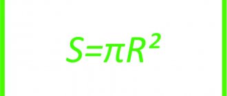
equal to a third of the product of the area of its base and its height.
Cone volume formulas:
| V= | 1 | π R2h |
| 3 |
| V= | 1 | Soh |
| 3 |
where V is the volume of the cone, So is the area of the base of the cone, R is the radius of the base of the cone, h is the height of the cone, π = 3.141592.
What is taper? Formula for calculating taper. Designation of taper in drawings.
Taper . Taper is the ratio of the diameter of the base of the cone to the height. The taper is calculated using the formula K=D/h, where D is the diameter of the base of the cone, h is the height. If the cone is truncated, then the taper is calculated as the ratio of the difference between the diameters of the truncated cone and its height. In the case of a truncated cone, the conicity formula will look like: K = (Dd)/h.
Designation of taper in drawings . The shape and size of the cone is determined by drawing three of the listed dimensions: 1) the diameter of the large base D; 2) diameter of the small base d; 3) diameter in a given cross section Ds having a given axial position Ls; 4) cone length L; 5) cone angle a; 6) taper with . It is also allowed to indicate additional dimensions in the drawing as a reference.
The dimensions of standardized cones do not need to be indicated on the drawing. It is enough to indicate in the drawing the symbol of the taper according to the relevant standard.
Taper, like slope, can be indicated in degrees, as a fraction (simple, as a ratio of two numbers or as a decimal), or as a percentage. For example, a 1:5 taper can also be expressed as a 1:5 ratio, 11°25'16", with a decimal of 0.2 and a percentage of 20. For tapers used in mechanical engineering, OCT/BKC 7652 specifies a range of normal tapers. Normal tapers - 1:3; 1:5; 1:8; 1:10; 1:15; 1:20; 1:30; 1:50; 1:100; 1:200. Also 30, 45, 60, 75, 90 and 120° can be used.
Volume of a cone in terms of radius
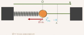
This triangle
to obtain a cone it must rotate around one of its
legs
, which is not only the axis of rotation, but also the height of the cone.
The second
leg becomes the radius of the circle-base of the cone obtained as a result of rotation, and the hypotenuse will be the apothem (the height lowered at a right angle to the line of the circle, and not the center).
Technical cone
with a cylinder is identical to the relationship between a pyramid and a cube (parallelepiped), the only thing is that the derivation
of the formula
goes through the relationship of the integrals of their spherical angles, but nevertheless, just like a pyramid, it occupies one third of the cylinder into which it can be inscribed.
Therefore its volume
is equal to the product of the area of the base and the height divided by three, or the product of the number
π
by the square of the radius and the height divided by three.
Formula for determining taper
You can independently calculate the taper by using various formulas. It is worth considering that in most cases the indicator is indicated in degrees, but it can also be expressed as a percentage - it all depends on the specific case. The calculation algorithm is as follows:
- K=Dd/l=2tgf=2i. This formula is characterized by the fact that the taper is characterized by a double slope. It is based on obtaining the value of the major and minor diameters, as well as the distance between them. In addition, the angle is determined.
- Tgf=D/2L. In this case, the length of the segment that connects the large and small diameters, as well as the indicator of the large diameter, is required.
- F=arctgf. This formula is used to convert the indicator to degrees. Today, in most cases, degrees are used, since they are easier to maintain when directly carrying out constructions. As for percentages, they are often indicated to enable the calculation of one of the diameters. For example, if the ratio is 20% and a smaller diameter is given, then you can quickly calculate the larger one.
As previously noted, the 1:5 taper and other indicators are standardized. For this, GOST 8593-81 is used.
Calculations are not shown in the drawing. As a rule, an additional explanatory note is created for this purpose. It is quite simple to calculate the basic parameters; in some cases, a drawing is constructed, after which the angle value and other indicators are measured.
Volume of a truncated cone
A truncated cone will be obtained if a section is drawn in the cone parallel to the base. The body bounded by this section, the base and the lateral surface of the cone is called a truncated cone.
The first way to calculate the volume of a truncated cone
The volume of a truncated cone is calculated by the formula:
[ LARGE V = frac{1}{3} left( Hcdot S_2 + h cdot s_1 right) ]
where: V – volume of the cone h – distances from the plane of the upper base to the vertex H – distances from the plane of the lower base to the vertex S1 – area of the upper (closest to the vertex) base S2 – area of the lower base
The second way to calculate the volume of a truncated cone
The volume of a truncated cone is calculated by the formula:
[ LARGE V = frac{1}{3} pi h left( R^2 + R cdot r + r^2 right) ]
where: V – volume of the cone h – height of the cone R – radius of the lower base r – radius of the upper base
Cone elements
Definition. Top of the cone
is the point (K) from which the rays emanate.
Definition. Cone base
is a plane formed by the intersection of a flat surface and all the rays emanating from the top of the cone. A cone can have bases such as circle, ellipse, hyperbola and parabola.
Definition. Generatrix of the cone
(L) is any segment that connects the vertex of the cone with the boundary of the base of the cone. The generatrix is a segment of the ray emerging from the vertex of the cone.
Formula. Generator length
(L) of a right circular cone through the radius R and height H (via the Pythagorean theorem): L2 = R2 + H2
Definition. Guide
cone is a curve that describes the contour of the base of the cone.
Definition. Side surface
cone is the totality of all the constituents of the cone. That is, the surface that is formed by the movement of the generatrix along the cone guide.
Definition. Surface
The cone consists of the side surface and the base of the cone.
Definition. Height
cone (H) is a segment that extends from the top of the cone and is perpendicular to its base.
Definition. Axis
cone (a) is a straight line passing through the top of the cone and the center of the base of the cone.
Definition. Taper (C)
cone is the ratio of the diameter of the base of the cone to its height. In the case of a truncated cone, this is the ratio of the difference in the diameters of the cross sections D and d of the truncated cone to the distance between them:
| C= | D | and C = | D–d |
| H | h |
where C is the taper, D is the diameter of the base, d is the diameter of the smaller base and h is the distance between the bases. Taper characterizes the sharpness of the cone, that is, the angle of inclination of the generatrix to the base of the cone. The greater the taper, the sharper the angle of inclination. The cone angle α will be:
| α = 2arctg | R |
| H |
where R is the radius of the base, and H is the height of the cone.
Definition. Axial section
cone is a section of a cone by a plane passing through the axis of the cone. Such a section forms an isosceles triangle, the sides of which are formed by generators, and the base of the triangle is the diameter of the base of the cone.
Definition. Tangent plane
to the cone is a plane passing through the generatrix of the cone and perpendicular to the axial section of the cone.
Definition. A cone that rests on a circle, ellipse, hyperbola or parabola is called circular, elliptic, hyperbolic,
or
parabolic
cone (the last two have infinite volume).
Definition. Straight
A cone is a cone whose axis is perpendicular to the base. For such a cone, the axis coincides with the height, and all generatrices are equal to each other.
Formula. Volume of a circular cone
:
| V= | 1 | πHR2 |
| 3 |
where R is the radius of the base, and H is the height of the cone.
Formula. Lateral surface area
(Sb) of a straight cone through the radius R and the length of the generatrix L: Sb = πRL
Formula. Total surface area
(Sp) of a right circular cone through the radius R and the length of the generatrix L: Sp = πRL + πR2
Definition. Oblique (oblique)
A cone is a cone whose axis is not perpendicular to the base. For such a cone, the axis does not coincide with the height.
Formula. Volume of any cone
:
| V= | 1 | SH |
| 3 |
where S is the area of the base, and H is the height of the cone.
Definition. Truncated
cone is the part of the cone that is located between the base of the cone and the section plane, parallel to the base.
Formula. Volume of a truncated cone
:
| V= | 1 | (S2H – S1h) |
| 3 |
where S1 and S2 are the areas of the smaller and larger base, respectively, and H and h are the distance from the top of the cone to the center of the lower and upper base, respectively.
Designation of taper in the drawing
When creating technical documentation, all established standards must be taken into account, otherwise it cannot be used in the future. When considering the taper designation in the drawings, attention should be paid to the following points:
- The diameter of the large base is displayed. The figure under consideration is formed by a body of rotation, which is characterized by a diametrical indicator. In the case of a cone, there may be several of them, and the change in the indicator occurs smoothly, not stepwise. As a rule, such a figure has a larger diameter, as well as an intermediate one if there is a step.
- The diameter of the smaller base is applied. The smaller base is responsible for forming the required angle.
- The length of the cone is calculated. The distance between the smaller and larger bases is an indicator of length.
- Based on the constructed image, the angle is determined. As a rule, appropriate calculations are carried out for this. In the case of determining the size from a printed image, using a special measuring device, the accuracy is significantly reduced. The second method is used when creating a drawing for the production of non-critical parts.
The simplest designation of taper also provides for displaying additional dimensions, for example, reference. In some cases, a taper sign is used, which makes it immediately clear about the difference in diameters.
There are quite a large number of different standards that relate to the designation of taper. The features include the following:
- The angle can be specified in degrees as a fraction or as a percentage. The choice is made depending on the area of application of the drawing. An example is that in the mechanical engineering field the value of a degree is indicated.
- In the mechanical engineering field, the concept of normal taper is included in a special group. It varies within a certain range and can be 30, 45, 60, 75, 90, 120°. Similar indicators are characteristic of most products that are used in the assembly of various mechanisms. At the same time, it is much easier to maintain such values when using turning equipment. However, if necessary, inaccurate angles can be maintained, it all depends on the specific case.
- When drawing the main dimensions, a drawing font is used. It is characterized by quite a large number of features that must be taken into account. Tabular information is used for correct display.
- To begin with, the taper icon is indicated from which the arrow is drawn and the value is displayed. The display features largely depend on what kind of drawing. In some cases, a large number of different sizes are applied, making taper application much more difficult. That is why it is possible to use several different methods for displaying such information.
Basic properties of a circular cone
1. All generators of a right circular cone are equal to each other.
2. When a right triangle rotates 360° around its side, a right circular cone is formed.
3. When an isosceles triangle rotates 180° around its axis, a right circular cone is formed.
4. At the point where the cone intersects a plane parallel to the base of the cone, a circle is formed. (see cut cone)
5. If, upon intersection, the plane is not parallel to the base of the cone and does not intersect with the base, then an ellipse is formed at the intersection (Fig. 3).
6. If the section plane passes through the base, then a parabola is formed at the intersection (Fig. 4).
7. If the section plane passes through the vertex, then an isosceles triangle is formed at the intersection (see Axial section).
8. The center of gravity of any cone is one-fourth of the height from the center of the base.
Definition and elements of a cone
A cone is understood as a body consisting of a circle and a point that is removed from its surface at a certain distance.
In this case, the point is connected to the base by drawing rays, which are called generators. The line connecting the center of the circle with the distant point is the height of this figure.
Note!
There is also such a thing as the cone axis. This is a line passing through its center and coinciding with the height. Generators are constructed relative to the axis.
I would like to consider a few more concepts on this topic:
1. By taper we mean the ratio of the diameter of the base of a figure and its height:
Important!
Taper is responsible for the angle of inclination of the generatrices. The larger this parameter, the sharper the angle.
2. An axial section assumes the presence of a plane that will dissect the figure, passing through the axis:
3. Tangent is a plane that is in contact with the generatrix of the cone. It is important that it is perpendicular to the axial section.
Enter the base radius and height of the cone
| Cone radius r | |
| Cone height h | |
| Result | |
| Calculation of the volume of a cube, pyramid, cone, cylinder, ball (volume of all figures). | |
| Volumes of figures | |
| Radius: | |
| Height: | |
| A cone is a geometric body that consists of a circle (the base of the cone), a point not lying in the plane of this circle (the top of the cone), and all the points connecting the top of the cone with the points of the base. Formula for the volume of a cone: , where R is the radius of the base, h is the height of the cone | |
Cone area formula
The surface area of a cone can be obtained by adding the area of the lateral surface and the area of the base of the cone:
S = Sside + Smain = πRL + πR2
Sources
- https://studwork.org/spravochnik/matematika/obemy-figur/obem-konusa
- https://calcsbox.com/post/formula-obema-konusa.html
- https://worksbase.ru/matematika/formuly/37-konus.html
- https://ru.onlinemschool.com/math/formula/volume/
- https://allcalc.ru/node/36
- https://ru.onlinemschool.com/math/formula/cone/
- https://www.calc.ru/1430.html
- https://MicroExcel.ru/obyom-konusa/
- https://www.calc.ru/obyem-konusa.html
- https://mnogoformul.ru/obem-konusa-formula-i-raschet-onlayn
Area of a truncated cone
To find this parameter you need to use the formulas:
- lateral surface area of the truncated cone Sside;
- the total area of the truncated figure Spol, which is equal to the sum of the areas of the two bases and the area of the lateral surface:
Here l is the length of the generatrix, and R and r are the radii of the larger and smaller bases, respectively.